

Installation and Operating Instructions
STEAMASTER
®
Electric Steam Cleaner Model: HPJ-2S
General Installation
06/14
- 1 -
IMPORTANT!
Please carefully review the contents of this
Manual prior to set-up and operation of your
steam cleaner. File this Manual in a safe place.
Pub. No. 908-F
Installation and Operating Instructions
Electric Steam Cleaner Model: HPJ-2S
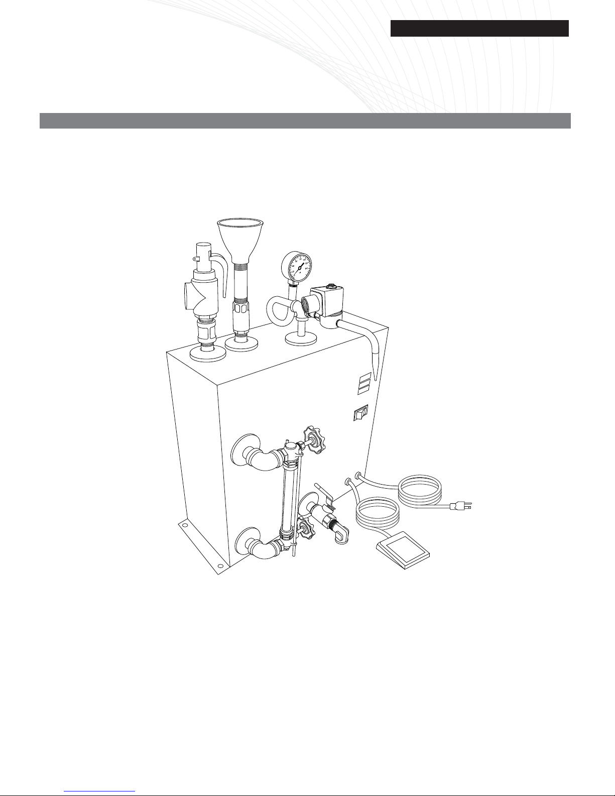
INST ALLATION AND ASSEMBLY INSTRUCTIONS
1. The Steamaster HPJ-2S steam cleaner should only be
placed on a sturdy work table, and positioned for accessible use and drainage.
2. Place the Steam Release Foot Pedal on the floor in a
convenient area for ease of foot operation.
3. Make certain the 3-Position Toggle Switch on the side of
the machine is OFF which is in the center position. The
switch turns off all electrical power to the machine.
4. Before plugging in the electrical cord, check you ELECTRIC CURRENT which must correspond to that indicated
on the nameplate located on the side of the machine.
Steamaster HPJ-2S units (except 240-Volt special orders)
are wired for 15 amps, 120 Volt operation in any standard
120 Volt outlet. However, we recommend an isolated
(20-amp line).
WARNING: The Safety Value must be pointed in a direction in
which it can release without causing personal injury or property
damage. If necessary have a plumber pipe the outlet to a safe
location. When piping the discharge outlet, do not pipe it in a
manner which would restrict it's flow.
OPERATING INSTRUCTIONS
Air Venting the System. The following procedure will expedite
the water fill procedure and operation.
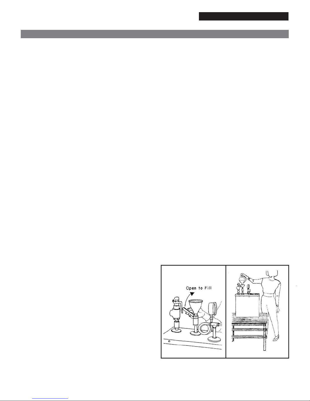
1. Open Funnel Valve (Fig. 1) by raising handle at top of
machine.
IMPORTANT! Water in machine MUST always be kept above
LOW LEVEL MARK on Glass Gauge (½" from bottom of Glass
Gauge). Water must be added at this time.
2. Place the Rocker Switch in the Fill position. This will
energize (open) the steam solenoid valve and allow air to
escape when water is added to the machine.
3. Fill with clean water until water level reaches the HIGH
LEVEL MARK on glass gauge, about 6½ quarts (Fig. 2).
Place Rocker switch in the OFF position. Close the funnel
valve.
4. Place Rocker Switch in the Heat Cycle position. The
HEATING Light will now go on, indicating that machine is
now heating up and building steam pressure.
5. Allow machine to heat up (at least 45 minutes) until
maximum (75-80 PSI) is reached. Check pressure gauge.
HEAT light will go out indicating when the machine has
reached maximum pressure. You will notice that HEAT
Light comes on from time to time, as the pressure drops,
and must be built up again.
6. Use the Foot Pedal to release steam, or place the Rocker
Switch to the STEAM position to get constant steam.
NOTE: At each usage, do not steam directly on jewelry as
there is condensation in the steam release pipe which must be
released before steaming jewelry. Depress the Steam Release
Foot Pedal to discharge condensation into sink or other vessel.
After condensation has been discharged (approximately 5
seconds), the machine will be ready to steam jewelry.
7. To refill the Steam Cleaner during operation: Place the
Rocker Switch in the FILL STEAM position. This will
release steam pressure. Check Steam pressure Gauge.
When there is NO STEAM PRESSURE, open the Funnel
Valve and fill to the HIGH WATER MARK level in the
Water Level Gauge. Close Funnel Valve. Return Rocker
Switch to Heat Cycle position and allow cleaner to build
pressure.
8. When Machine is Finished for the Day - Place Rocker
Switch in the "OFF" position.
For Best Cleaning Results - Always depress Steam Release
Foot Pedal for about five seconds to remove excess condensation. Carefully hold item to be cleaned With tweezers approximately one inch below the Steam Nozzle.
To clean trays of merchandise, hold tray about five Inches
below Steam Nozzle. Move tray In a rapid side to side motion
while steam cleaning.
NOTE: Do not attempt to clean soft, porous stones such
as Opals. Nor, is it advisable to steam clean precious
stones which have cracks. Do not steam clean stones
exposed to extreme cold temperatures until they reach
room temperature.
SPECIAL PRECAUTIONS
Live steam can cause bodily injury. Exercise care not to come
in contact with the Steam Line during operation. Fittings on the
machine are HOT and should not be touched during operation.
Place the Steam Release Foot Pedal in a location where it will
not be accidentally depressed.
NOTE: Every time water is added to the steam cleaner air
enters the boiler and will cause the pressure to build to a level
which is a few pounds higher than normal. This condition will
return to normal when the air is released by releasing some
steam.
06/14
- 2 -
Pub. No. 908-F

Installation and Operating Instructions
Electric Steam Cleaner Model: HPJ-2S
TROUBLESHOOTING YOUR STEAM ASTER
MODEL HPJ-2S
When starting up, machine fails to operate:
1. Check to see if plug is in electrical outlet. Is outlet good?
2. Check fuses in your main power supply.
3. Recheck your start-up operation steps.
Machine cuts off while operating:
A low water condition can activate Manual Reset Low Water
Cut-Off Switch, reset light will come on. If this should
happen, follow this procedure.
1. Bleed out all steam pressure in generator.
2. Fill water up to high level mark on Glass Gauge.
3. Push Reset Button on side of machine.
NOTE: Reset Button is to be used ONLY when machine
cuts-off due to a low water condition!
(When low water cut off is activated) under normal
conditions it is not necessary to use reset button.
4. Pilot Light will go on indicating that machine is now
operational.
IMPORTANT! If Pilot Light fails to go on after following
above instructions, check fuses in your main power supply.
Condensation forms each time machine is used:
This is a normal condition. Always depress lever of Steam
Release Pedal Valve for about five seconds to remove
excess condensation at each usage.
MAINTENANCE INFORMATION
During the first week of operation only, drain boiler at least
every other day. In order to extend the life of the machine,
drain boiler at least once each week under 10 Ibs. of steam
pressure, with electric current turned off.
After draining, flush out boiler with plain water, then refill
machine to high level mark on Glass Gauge. Drain Valve is
located on lower left side of the machine.
The exterior metal cabinet and parts should be wiped off
on a regular basis with a damp cloth to maintain the new
appearance of the machine. Do not allow the parts to
become clogged with dirt and grime.
IMPORTANT! Water in machine MUST always be kept
above LOW level mark on Glass Gauge (½" from bottom of
Glass Gauge) in order to protect and extend the operating
life of the heating element.
WARNING: Steam slowly erodes the sight glass. To
prevent the sudden breakage or explosion of the gauge
glass. It must be inspected on a regular basis for signs of
deterioration.
Sight Glass Inspection: The sight glass should be
inspected for deterioration each time the unit is refilled.
Scratches, corrosion, chips, surface flaws, cracks, or nicks
weaken the glass. To examine for these imperfections shine
a very bright concentrated light at about 45 degree angle.
Anything which glistens and catches the fingernail or any
star-shaped or crescent-shaped mark which glistens is
cause for replacement. Any gauge glass which appears
cloudy or roughened and cannot be cleaned with commercial
glass cleaners, should be replaced.
Model HPJ-2S - General Arrangement
80
60
100
40
120
140
20
psi
0
16 3/4"
16 3/4"
18"
06/14
FILL/STEAM
HEATING
RESET
HEAT
OFF
CYCLE
MANUAL
RESET
6 1/2"
11 1/2"
- 3 -
25 1/2"
Pub. No. 908-F

Installation and Operating Instructions
Electric Steam Cleaner
MODEL HPJ-2S PARTS LISTING
ITEM
1
2
3
4
5
6
7
8
9
10
11
12
13
14
15
16
17A
17B
17C
18
19
19A
20
21
22
23
24
PART NO.
N/A
N/A
006-6348
007-4114
007-4102
007-1212
005-1014
007-1260
006-3207
005-2138
007-4105
006-3216
007-1102
005-2074
005-2122K
005-2023
007-1240-1
007-1240-2
007-1240-3
007-5275
006-3215
005-2017
007-1205
006-4201
007-1122
002-1075
007-1129
Tank
Cabinet
Heating Element 120V, 1.5kW
Pressure Control
Thermodisc High Limit Reset Switch
Water Gauge Fixture Top and Bottom
Elbow, ½”NPT
Water Gauge Friction Washer
Water Gauge Rubber Washer
Gauge Glass Packing Nut
Gauge Glass, ⅝” x 8”L
Aluminum Nozzle
¼" Steam Solenoid Assembly
Pig Tail
¼” Adaptor with Strainer (inside)
"L" Shape Nipple (¼" Male THD x ⅛" FTHD
Indicator light Fill/Steam, Orange
Indicator light Heat, Orange
Indicator light Reset, Red
Rocker Switch
Funnel
½” x 3” nipple
½" Ball Valve, Fill/Drain
Gasket for heating element
Electric Foot Switch – Pedal
Cord with plug
Pressure Gauge
DESCRIPTION
QTY
1
1
1
1
1
1
2
2
2
2
1
1
1
1
1
1
1
1
1
1
1
1
2
1
1
1
1
Model: HPJ-2S
ITEM
To order replacement parts:
When ordering replacement parts for your Steam Cleaner
please provide your authorized Steamaster Sales Agent
with both the part number and description.
wiring Diagram
25
26
27
120 VAC
PART NO.
007-1214
005-1101
005-2109
BK
GN
WT
HEATING LIGHT RESET LIGHT
½" Safety Valve 100psi
¼" x 1½", nipple
Street Elbow ½" x ½"
3
TEMPERATURE
HEATING
ELEMENT
CONTROL
4
18
SWITCH
DESCRIPTION
FILL
HEAT
FILL
HEAT
5
LOW WATER
CUT-OFF
1717
FOOT SWITCH
22
STEAM
SOLENOID
VALVE
FILL/STEAM
LIGHT
17
QTY
1
1
1
13
HPJ-2S Exploded View
24
19
24
14
19A
25
11
20
10
6
8
7
9
2
Details "A"
Details "A"
IMPORTANT:
Please fill out and retain for your records. See label on machine for Serial
Number.
Model No.
Serial No.
Date Purchased
Purchased from
27
26
15
17
18
4
20
STEAMASTER CO., INC.
East Rutherford, NJ 07073
Tel. (201) 933-5800
13
16
12
5
23
3
21
22
25 East Union Ave
Fax (201) 933-0746
1
06/14
- 4 -
Pub. No. 908-F
 Loading...