


INSTALLATION GUIDE
for the
SB-VW-CC/10W3v3
SKU# 94535
2008 - 2012
Thank you for choosing a JL Audio Stealthbox® for your automotive sound system.
With proper installation, your new vehicle-specific enclosed subwoofer system
will deliver years of listening pleasure.
We strongly recommend that you have your new Stealthbox® installed by your authorized
JL Audio dealer. The installation professionals employed by your dealer have the necessary tools
and experience to disassemble and reassemble your vehicle properly. Also, keep in mind that your
warranty coverage extends to 2 years if your system is installed or approved by
your authorized JL Audio dealer. If you prefer to perform your own installation,
please read this installation guide completely before beginning the process.
If you choose to per form the installation yoursel f, it is abso lutely vital that
the Stealthbox
®
be properly mo unted to the vehicle according to these
instructions . Failure to mount the enclosure prop erly presents two problems:
1) The sub-bass per formance will suffer due to the movement of the enclosure
caused by the force exe rted by the woofer(s).
2) A loose enclosure pres ents a serious safety haza rd in the event of a collision
or sudden deceleration.
Continued on Next Page
SB-VW-CC/10W3v3 INSTR_ SKU# 011333
IN STALL ATIO N
DIFFICULTY:
3
5
OUT
OF
ESTIMATED TIME:
23 HOURS
STEP 3
Carefully unclip and remove the trunk sill panel.
STEP 2
Remove the trunk floor panel.
STEP 1
Empty out the trunk of the car so that you have a clean area
to work in.
Continued on Next Page
SB-VW-CC/10W3v3 INSTR_ SKU# 011333
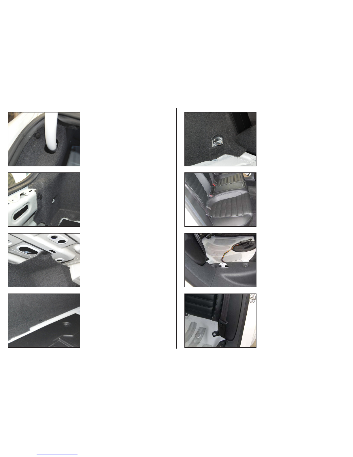
STEP 7
Remove the screw holding the trunkliner to the floor.
STE P 11
Remove the screw that holds in the driver’s side rear seat
bol ster.
STEP 6
Remove the clip holding the trunkliner to the underside of
the deck.
ST EP 10
Pictured is one of the hooks that hold the rear seat cushion
in place. Unclip and remove the cushion.
STEP 5
Remove the clip holding the trunkliner to the rear of the
trunk.
STEP 9
Open the rear doors to begin the removal of the rear seat
cushion and bolsters.
STEP 4
Remvoe the clip holding the driver’s side trunkliner to the
side of the trunk.
STEP 8
Remove the two cargo ho ok screws, and remove the hook.
Page 2 • JL Audio, Inc., 2012

Continued on Next Page
SB-VW-CC/10W3v3 INSTR_ SKU# 011333
Page 3 • JL Audio, Inc., 2012
ST E P 15
Attach speaker cable to the enclosure, and set it into position
on top of the spacer as shown.
ST EP 19
Place a 1/4” Flat Washer over a 1/4 - 20 x 1” Bolt, and slide the
bolt through the square hole in the brace from the back ,
then through the hole in the Top Bracket. T hread a 1/4” Flat
Washer, a 1/4” Lock Washer, and a 1/4 - 20 Hex Nut onto the
bolt as shown, and firmly tighten.
ST E P 14
Pictured is the spacer for the Stealthbox®. Place the spacer
into the Stealthbox® location, aligning the four holes with the
four studs in the flo or of the trunk.
ST EP 18
Locate the square hole indicated in the brace near the trunk
lid hinge.
ST E P 13
Remove the driver’s side trunk liner.
ST E P 17
Secure the Top Bracket to the Stealthbox® using a 1/4 - 20 x
1” Bolt, a 1/4” Lock Washer, and a 1/4” Flat Washer as shown.
ST E P 12
Fold the rear seat back down. Caref ully unclip the bolster
and remove it from the vehicle. Pictured is the back side of
the bolster to show the location of the clips. Repeat Steps
11-12 for the passenger side.
ST EP 16
Secure the Side Bracket to the Stealthbox ® using a 1/4 - 20 x
1” Bolt, a 1/4” Lock Washer, and a 1/4” Flat Washer as shown.
Secure the Side Bracket to the f loor using the factory nut as
shown.

Continued on Next Page
SB-VW-CC/10W3v3 INSTR_ SKU# 011333
Page 4 • JL Audio, Inc., 2012
STEP 23
Using the four pilot holes on the Template as a guide, drill
through the rear deck using a 1/8” drill bit.
STE P 27
Drill a pilot hole near the corner of each of the marked
openings large enough to accomodate the saw blade in the
next step.
STEP 22
Align the template with one o f the recesses in the rear deck,
and trace the four openings onto the panel as shown.
STEP 26
Cut away the padding from the underside of the rear deck as
shown. Repeat Steps 22-26 for the opposite side.
ST EP 21
Unclip the screw covers on the rear deck , and remove the
screws and hooks . Remove the rear deck.
STEP 25
Turn over the rear deck, reposition the Template as shown,
and trace the outer perimeter of the Template.
STEP 20
Carefully unclip the driver ’s side C-pillar panel. Repeat for the
passenger side.
STEP 24
Pictured is the rear deck with the openings marked.

Continued on Next Page
SB-VW-CC/10W3v3 INSTR_ SKU# 011333
Page 5 • JL Audio, Inc., 2012
ST EP 31
Secure the Grille Panels to the rear deck using the 10 #8 x
1/2” Wafer Screws.
STEP 30
Align the two Grille Panels over the openings as sh own.
CO NGR ATUL ATION S!
You have completed the installation for this model!
Enjoy your new Stealthbox® !
Please refer to the Power Re commendation se ction for
an amplifier re commendation and basic set-up help.
STEP 29
Pictured is the rear deck af ter the openings have been cut
out.
STE P 33
Reinstall the trunk sill panel and trunk floor panel.
STEP 28
Cut out each of the marked openings.
STE P 32
Reinstall the trunk liner, rear deck, C-pillar panels, rear seat
bolsters, and rear seat cushion.

SB-VW-CC/10W3v3 INSTR_ SKU# 011333
Page 6 • JL Audio, Inc., 2012
INCLUDED HARDWARE
(1) Spacer (1) Grille Template (3) 1/4” Lock Washer
(1) Driver Grille (3) 1/4 - 20 x 1” Bolt (1) 1/4 - 20 Hex Nut
(1) Passenger Grille (4) 1/4” Flat Washer (10) #8 x 1/2” Wafer Screw
SPECIFICATIONS
Enclosure Type: Acoustic Suspension (sealed)
Driver Type: 10W3v3-2
Nominal Impedance: 2 ohm
Continuous Power Handling: 500 watts
POWER RECOMMENDATION
JL Audio recommends hi gh quality ampliers such as the J L Audio XD700/5 or XD30 0/1. The diagra m below
shows the recommen ded crossover settings for the XD300/1. If another a mplier is being used, please re ference this illustration a nd use similar settings on that ampli er.
All JL Audio amplier s are very versatile audio compo nents. Please consult the owner’s manua l for even more
detailed information about installing and tuning your amplier.
CONNECTIONS
Using quality powe r, signal an d speaker wire is essential in ensuring the p erformance of your Stealthbox®.
JL Audio recommends u sing a 4 AWG power kit such as the XD-PCS 4-1B for your Stealthb ox® amplier. Other
kits are availabl e should you be using more than one ampli er. Signal wire such as the JL Audio Premium
Audio Interconnec t Cables should be used that will prov ide signal for both channels of the amp lier. JL Audio
reccommends using 12AWG speaker wire for sub woofers such as our XC-BCS12-25.
MID/HIGH FREQUENCY DRIVER FITMENT
A variety of JL Au dio coaxial and component syste ms will t in the factory speake r locations of you vehicle.
Front Speaker Size / Locatio n: 6-1/2”- Front Doors
Fits J L Audio Mo dels: TR650- CXi, TR650-CSi, C2- 650x, C2-650, C3-650,
C5-650x , C5-650, & ZR650-C Si
Rear Speaker Siz e / Location: 6-1/2”- Rear Door
Fits J L Audio Mo dels: TR650- CXi, TR650-CSi, C2- 650x, C2-650, C3-650,
C5-650x , C5-650, & ZR650-C Si
All specifications are subject to change without notice. “JL Audio®” and the JL Audio logo, “Stealthbox” and the Stealthbox logo are registered
trademarks of JL Audio, Inc.,. “Ahead of the Curve” and its respective logo is a trademark of JL Audio, Inc.,.
JLA-SKU# 94535 01.25.2012 • Printed in USA • ©2011 JL Audio, Inc.,. • U.S. PATENTS: #5,734,734 #5,949,898 #6,118,884 #6,229,902 #6,243,479
#6,294,959 #6,501,844 #6,496,590 #6,441,685 #5,687,247 #6,219,431 #6,625,292 #D472,891 #D480,709 Other U.S. & Foreign patents pending.
For more detailed information please visit us online at www.jlaudio.com.
(954) 443-1100
www.jlaudio.com
10369 NORTH COMMERCE PARKWAY • MIRAMAR, FLORIDA • 33025 • USA
 Loading...