

Stealthbox SB-T-TDCMAX/13TW5, Stealthbox SB-T-TUNDCMAX/13TW5, Stealthbox SB-T-TUNDCMAX/13TW5/DG, SB-T-TUNDCMAX/13TW5 Installation Manual

I N S T A L L A T I O N G U I D E
for th e
SB-T-TUNDCMAX/13TW5
SKU#94410
2007-Up Toyota Tundra CrewMax
Thank you for choosing a JL Audio Stealthbox® for your automotive sound system. With proper
installation, your new vehicle-specific enclosed subwoofer system will deliver years of listening pleasure.
We strongly recommend that you have your new Stealthbox® installed by your authorized JL Audio
dealer. The installation professionals employed by your dealer have the necessary tools and experience
to disassemble and reassemble your vehicle properly. Also, keep in mind that your warranty coverage
extends to 2 years if your system is installed or approved by your authorized JL Audio dealer. If you
prefer to perform your own installation, please read this installation guide completely
before beginning the process.
If you choose to perform the installation yourself, it is absolutely vital that
the Stealthbox® be properly mounted to the vehicle according to these
instructions. Failure to mount the enclosure properly presents two problems:
1) The sub- bass performance will suffer due to the movement of the enclosure
caused by the force exerted by the woofer(s).
2) A loose enclosure presents a serious safety hazard in the event of a collision
or sudden deceleration.
S T E P 1
Remove anything stored behind the rear seats and fold both
seats forward.
Test Stealthbox® for proper operation before
continuing!
Using a Phillips head screwdriver remove the woofer(s)
from the enclosure(s). The grille(s) do not need to be
removed from the woofer(s)! They were removed in later
pictures for this document but they do not need to be.
Continued on Next Page
S T E P 2
Along the outside of the plastic panel that covers the back
of the cab on the drivers side, locate the seam between
the back and, side panels. Line up the first (or only)
enclosure with this seam.
If installing two enclosures, verify that there is adequate
room between the first enclosure and the elevated part
of the rear panel on the passengers side (as seen in the
photo for step (1)) to fit the second enclosure.
SB-T-TUNDCMAX/13TW5 INSTR_SKU# 011266
INS TALLATIO N
D I F F I C U LT Y :
35
OU T
OF
EST IMATED TIME:
23 HO URS
This manual applies to both single and dual Stealthbox® installations.
S T E P 3
Using a 1/8" drill, use the hole in the enclosure centered
behind the woofer as a guide, to drill a hole through the
plastic (and only the plastic) that covers the back of the
cab.
*CAUTION*
Before drilling, always make sure that you are not
going to be drilling into any gas lines, brake lines,
transmission lines, electrical wiring, exhaust systems
or anything else that might cause a reduction in
your weekly pay. Always wear eye protection when
drilling.
Continued on Next Page
SB-T-TDCMAX/13TW5 INSTR _SKU# 011266
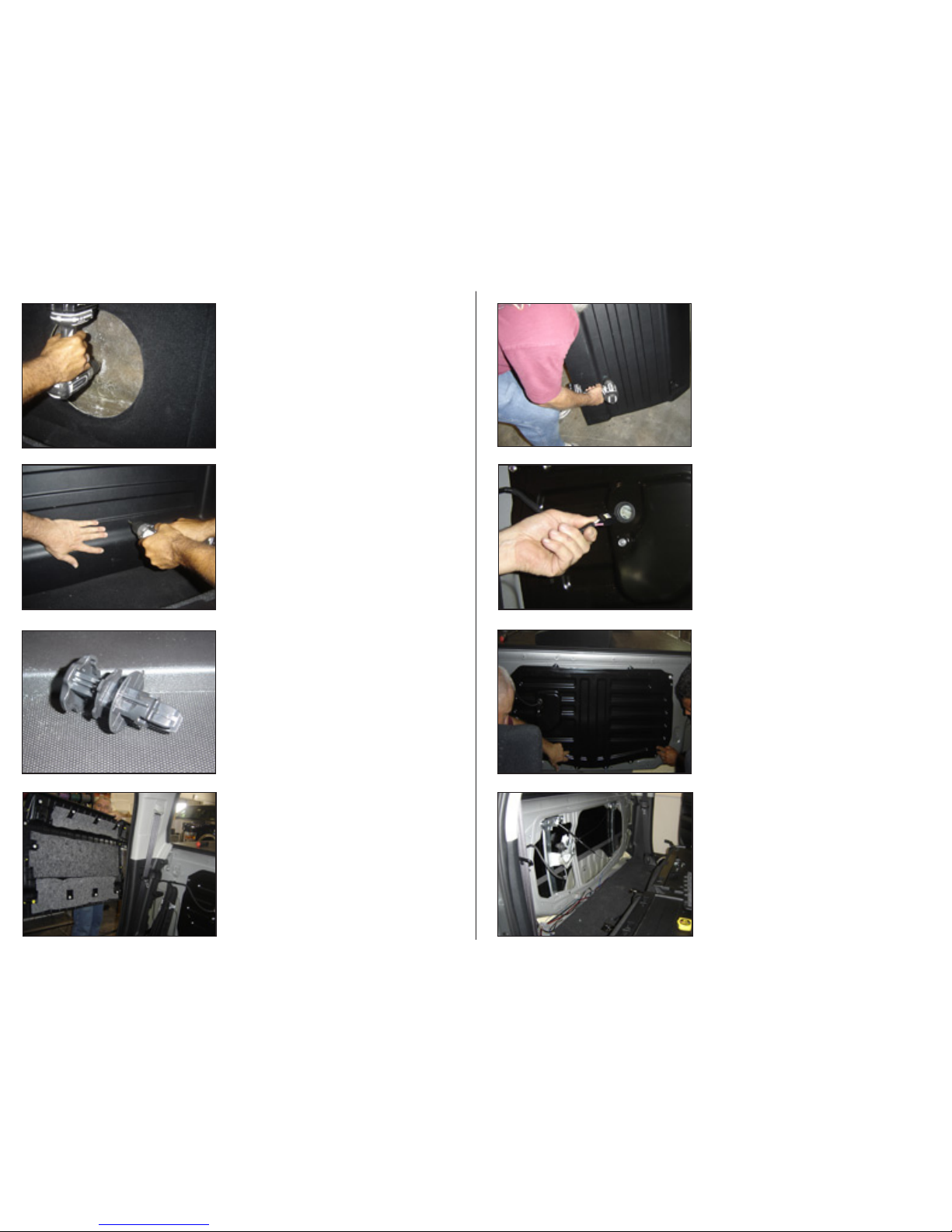
S T E P 5
Remove the enclosure and ensure that the rear window
of the truck is in the UP position. Using the hole that was
drilled in steps 3,4 as a guide, drill a 1/8" hole through the
metal panel that is behind the interior plastic panel (make
sure to drill a hole for each Stealthbox® installed). Use caution to drill only through the metal panel.
Repeat this step if installing second Stealthbox®.
***Please follow safe drilling procedures***
S T E P 4
If installing two Stealthbox® enclosures, center the second
enclosure between the first and the raised portion of the rear
panel. Repeat Step 3 for the second enclosure.
***Please follow safe drilling procedures***
After the guide hole is drilled, enlarge the hole in
the Stealthbox® to 3/8", this hole will eventually mount
the enclosure.
Page 2 • JL Audio, Inc 2008
S T E P 7
Enlarge the 1/8" holes previously drilled step 3 and 4
in the plastic trim to 3/8".
S T E P 6 ( d E T A I l )
Remove the interior rear plastic trim panel. This panel is
held in with push-in plastic fasteners that will pull out
relatively easily when the panel itself is gently pulled
from around the edges.
S T E P 6 There are two anchors for cargo in the
upper corners of the rear plastic trim panel. These two
anchors need to be removed in order to remove the
trim panel. To remove these, pull on the outside of the
anchor top section it will pull out, allowing the anchor
itself to collapse and be pulled out.
S T E P 8
Unplug the power harness from the rear window motor.
S T E P 1 0
Now is an excellent oppurtunity to install some sound deadening material to the inside of the back of the cab of the
truck. We also suggest covering the back of the metal panel
that was just removed in step 9 with a sound deadening
material.
S T E P 9
Remove metal rear cab panel (black panel) from the inside
of the truck by removing all interior bolts from perimeter.

Continued on Next Page
SB-T-TDCMAX/13TW5 INSTR _SKU# 011266
S T E P 1 1
Enlarge 1/8" hole drilled in step 5 through the metal panel
to 3/8" as was done on the plastic panel. Repeat this step if
installing second Stealthbox®.
Page 3 • JL Audio, Inc 2008
S T E P 1 4
Reinstall rear interior metal panel, making sure the the bolt(s)
that were installed in Step 13 are facing forward. Use caution so that the cable that was un-plugged in Step 8 does
not get pinched between the removeable panel and the
back of the cab. Plug the cable back in to where it was
unplugged.
S T E P 1 3
Tighten this hardware down using either a deep-well socket
and a wrench (as shown) or two wrenches. You want to
make sure that this hardware won’t move, as this will be
how the Stealthbox® is secured to the truck.
S T E P 1 2
Install included hardware as shown in the picture at left and
the illustration below. Repeat this step if installing second
Stealthbox®.
LOCK WASHER
HEX HEAD BOLT
FRONT OF TRUCK
FENDER WASHER
REMOVEABLE INTERIOR
REAR WALL
HEX NUT
FENDER WASHER
S T E P 1 2 ( d E T A I l )
S T E P 1 7
If installing two Stealthboxes®, install the driver side
enclosure first. Align the enclosure so that the stud goes
through the previously enlarged guide hole Step 4.
Start the hardware on the stud using a large fender
washer close to the fiberglass, a split lock washer then
the nut (see Step 18). Be cautious not to overtighten the
nut, it only needs to be snug.
S T E P 1 6
Re-install the two anchors that were removed in Step 6.
S T E P 1 5
Re-install the rear plastic trim panel. We found that lining up
the recently installed stud with the hole previously drilled in
the panel to the outside (drivers side) made alignment easier.
Ensure that all of the plastic plugs line up with their correct
receptacles and press them in place. Continue towards the
center of the truck. The rear panel can be installed in two
pieces which may make alignment easier. Make sure that the
second stud (for the second Stealthbox® if installed) and the
rest of the plugs line up.

SB-T-TDCMAX/13TW5 INSTR _SKU# 011266
Page 4 • JL Audio, Inc 2008
S T E P 1 9
We suggest wiring the enclosure at this point, it will be very
hard (or impossible) to access the terminal cup if the second
Stealthbox® is installed. Route the wire using a safe, secure
method to the amplifier location. Always ensure that wires
cannot be pinched or damaged along the path to the next
component.
If installing two Stealthboxes®, we suggest wiring the second
enclosure before mounting as the terminals will be much
more accessible than after the enclosure is mounted. Repeat
steps 17-19 for the second Stealthbox®.
S T E P 1 8
This is a cross-sectional drawing showing the bolt from step
13 also passing through the interior plastic trim panel and
the Stealthbox®. The bolt then holds the Stealthbox® in place
via the fender washer, split lock washer and, nut. Again, be
cautious not to overtighten the nut, it only needs to be snug.
LOCK WASHER
REMOVEABLE INTERIOR
REAR WALL
HEX NUT
FENDER WASHER
FRONT OF TRUCK
STEALTHBOX®
INTERIOR PLASTIC TRIM PANEL
COMPLETED IN
STEP 16
S T E P 2 0
Place the bottom edge of the woofer on the enclosure,
attach wires to the appropriate connectors. Lean the woofer
back into location and make sure that wires do not get
pinched either betwen the woofer and the enclosure or the
securing hardware.
S T E P 2 1
Use a sharp pointed object to align the woofer with the
holes previously used to mount it, re-mount the woofer. Use
a “crossing “ pattern as if re-mounting a repaired flat tire. If
installing two Stealthbox ® enclosures, repeat this procedure
in both enclosures. Again, the grilles did not need to be
removed!
C O N G R A T U L A T I O N S !
You have completed the installation for this model!
Enjoy your new Stealthbox®!
Please refer to the Power Recommendation section for an
amplifier recommendation and basic set-up help.
All specifications are subject to change without notice. “JL Audio®” and the JL Audio logo, “Stealthbox” and the Stealthbox logo are registered
trademarks of JL Audio, Inc. “Ahead of the Curve” and its respective logo is a trademark of JL Audio, Inc.
JLA-SKU# 011266 8-12-2008 • Printed in USA • ©2007 JL Audio, Inc. • U.S. PATENTS: #5,734,734 #5,949,898 #6,118,884 #6,229,902 #6,243,479
#6,294,959 #6,501,844 #6,496,590 #6,441,685 #5,687,247 #6,219,431 #6,625,292 #D472,891 #D480,709 Other U.S. & Foreign patents pending.
(954) 443-1100
ww w . j l a u d i o . co m
1 0 3 6 9 N O R T H C O M M E R C E P A R K W A Y • M I R A M A R , F L O R I D A • 3 3 0 2 5 • U S A
I N C L U D E D H A R D W A R E P E R S T E A L T H B O X ®
(1) 3/8-16 X 1 1/2" Hex Head Bolt
(3) 3/8 X 1 1/4" Fender Washer
(2) 3/8" Split Lock Wash er
(2) 3/8 X 16 Hex Nut
S P E C I F I C A T I O N S
Enclosure Type: Acoustic Suspension (sealed)
Driver Type: 13TW5-3
Nominal Imp edance: 3 ohms mono
Continuous Power Handling: 600 Watts
P O W E R R E C O M M E N D A T I O N
JL Audio recommends using a high quality amplifiers such as the JL Audio 500/1v2. The 500/1v2 could be used for
one or, two Stealthboxes. The ideal amplifier for two enclosures is the HD750/1. The diagram below shows the
recommended crossover, infrasonic filter and equalizer settings for the 500/1v2 when being used to power your
Stealthbox®.
The JL Audio 500/1v2 and the HD750/1 are very versatile audio components. Please consult the owner’s manual
for even more detailed information about installing and tuning these amplifiers.
M I D / H I G H F R E Q U E N C Y D R I V E R F I T M E N T
A variety of JL Audio coaxial and component systems will fit in the factory speaker locations of your vehicle.
Dash Speaker Size / JL Audio Model: 3.5” - TR350-CXi
Front Speaker Si ze / Location: 6”x 9” - Front Doors
Fits JL Audi o Models: TR690-TXi, VR690-CXi
Rear Speaker Size / Location: 6.5” - Rear Door
Fits JL Audi o Models: TR650-CXi, TR650-CSi, VR650-CXi, VR650- CSi,
C5-650, C5-650x, ZR650- CSi
+12VDC RemoteGround
JL AUDIO 500/1
five-channel system amplifier
+
_
_
+
Subwoofer Output
MONO OUTPUT ONLY
40
45
556585
120
200
Filter Freq. (Hz)
Mode / Slope
Off / 12dB / 24dB
Amp LP Filter
Infrasonic Freq. (Hz)
15
18
253040
50
60
Off / 30Hz
Infrasonic Filter
0.5
0.7
1.1
1.6
2.7
4.3
"Q"
20
25
354555
70
85
Center Freq.
0
+4
+10
+13
+15
Boost (dB)
Off / On
Bass EQ
Remote Bass Port
Advanced
Bass
Control
Preamp Output Section
Full Range / Amp Filter / Out Filter
Output Mode
Filter Slope
12dB / 24dB
40
45
556585
120
200
Filter Freq. (Hz)
Left Ch. Right Ch.
Filter Mode
LP / HP
Amplifier Input Section
Input Sens.
Left Ch. Right Ch.
Signal Sensing
Off / On
Input Voltage
Low / High
 Loading...