

Stealthbox SB-T-FJ/12W1v3 Installation Manual
IN STALL ATIO N
DIFFICULTY:
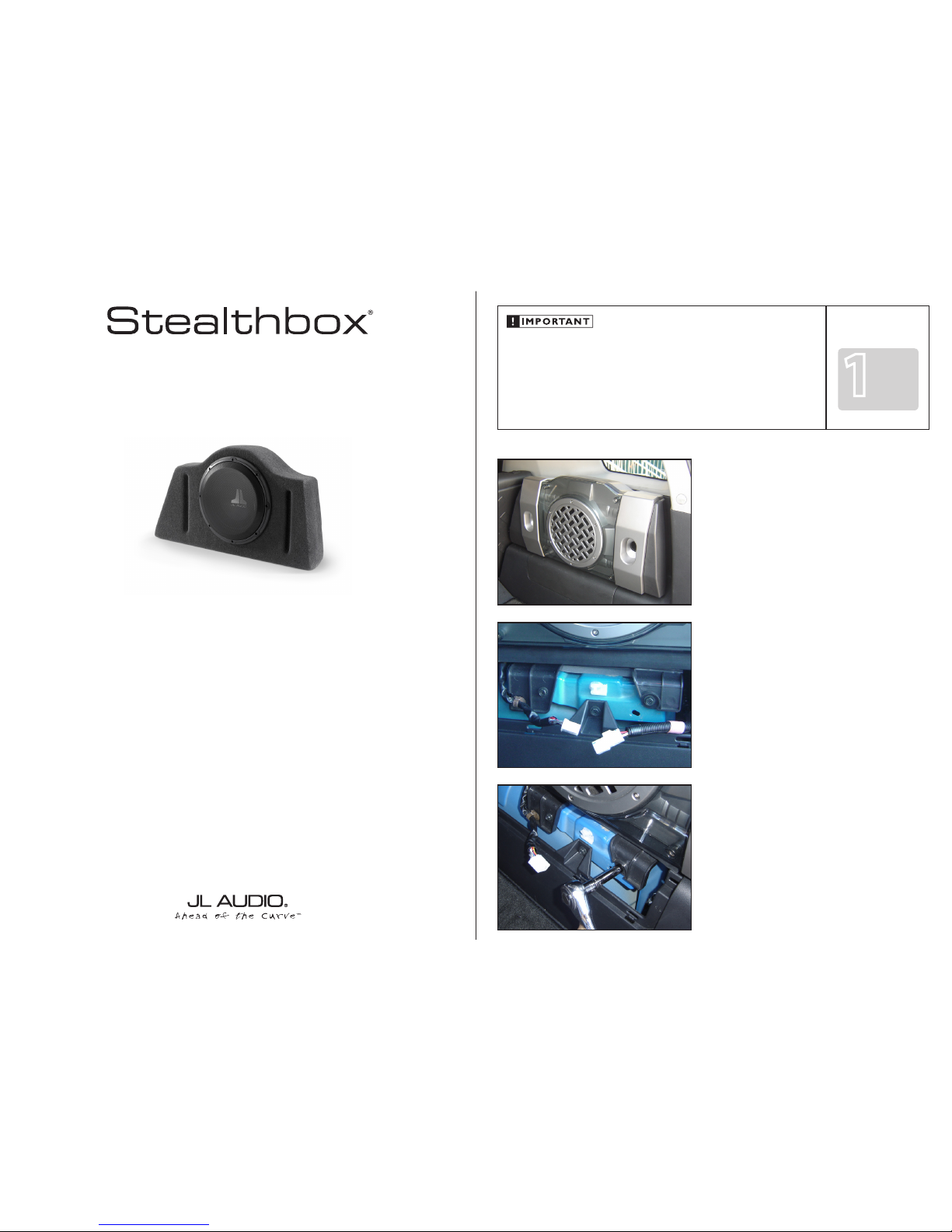
INSTALLATION GUIDE
for the
SB-T-FJ/12W1v3
SKU# 94310
2000 - 2014 Toyota FJ Cruiser
Thank you for choosing a JL Audio Stealthbox® for your automotive sound system. With proper installation, your new vehicle-
specific enclosed subwoofer system will deliver years of listening pleasure.
We strongly recommend that you have your new Stealthbox® installed by your authorized JL Audio dealer. The installation
professionals employed by your dealer have the necessary tools and experience to disassemble and reassemble your vehicle
properly. Also, keep in mind that your warranty coverage extends to 1 year if your system is installed or approved by your
authorized JL Audio dealer. If you prefer to perform your own installation, please read this installation guide completely
before beginning the process.
If you choose to per form the installation yoursel f, it is absolutel y vital that
the Stealthbox® be properly mo unted to the vehicle according to these
instructions . Failure to mount the en closure properly presents two p roblems:
1) The sub-bass per formance will suffer due to the movem ent of the enclosure
caused by the force exe rted by the woofer(s).
2) A loose enclosure presents a serious s afety hazard in the event of a collision
or sudden deceleration.
STEP 1
Remove all contents from cargo area.
If your vehicle did not come equipp ed with the factory
“woofer” system, go to STEP 7.
Continued on Next Page
STEP 2
Remove the access panel from under the factor y
“woofer” system.
Disconnect the white plug.
STEP 3
Remove the two mounting b olts that secure the bottom of
the factory “woofer” system.
SB-T-FJ/12W1v3_INSTR _SKU#011226
1
5
OUT
OF

Continued on Next Page
SB-T-FJ/12W1v3_INSTR _SKU#011226
STEP 7
Remove the factor y “woofer” system or the pocket from the
vehicle.
Vehicles without the fac tory “woofer” system, remove the
access panel that is located on the wheel well.
STEP 6
Remove the upper right mounting bolt.
STEP 5
Remove the upper lef t mounting bolt.
STEP 4
Loosen the four exposed screws and remove the grille p anel.
L-BRACKET
8mm FLAT WASHER
STEALTHBOX WALL
THREADED INSERT
8mm BOLT
SPACER
8mm LOCK WASHER
Page 2 • JL Audio, Inc 2016
STEP 9
Place the Stealthbox onto passenger’s side rear wheel well.
Place a supplied 6mm lock washer and 6mm flat washer
onto each of the supplied 6mm x 40mm bolts.
From inside the Stealthbox®, place one of the bolt assemblies
through the left mounting hole that is located on the rear
wall of the Stealthbox®.
STEP 11
Place the supplied pair of threaded studs into the 3 o’clock
and 9 o’clock position of the woofer’s mounting screw
locations. Leave about 1 1/2-inch exposed. As seen the
picture to the left.
Reconnect the sp eaker wires from inside the Stealthbox®
back onto the woofer’s terminal.
Place the woofer into the mounting hole, using the threaded
studs as guides. Mount the wo ofer using the mounting
screws that were removed in STEP 8. Remove the threaded
studs and secure the remaining p air of mounting screws.
STEP 10
From inside the Stealthbox®, place the other bolt assembly
through the right mounting hole that is located on the rear
wall of the Stealthbox®.
Secure both bolt assemblies.
STEP 8
With hand tools, unscrew the woofer’s mounting screws.
Disconnect the speaker wire from woofer and remove from
the woofer from the Stealthbox ®.
Place a supplied 8mm lock washer, 8mm flat washer,
L-bracket and spacer onto each of the supplied 8mm bolts.
Place the shorter length le g of the L-bracket onto the
8mm bolt.
Secure each bolt assembly onto the bottom of the
Stealthbox®. The longer length leg of each L-bracket is to be
positioned toward the front of the Stealthbox®.
 Loading...