

Page 1

USER MANUAL
Alternative Drive Controls
i-Drive® 4.0
Stealth’s User Manual and Maintenance Guide for i-Drive 4.0
Alternative Control with Bluetooth® Wireless Technology
Page 2

Customer Satisfaction 1.0
Stealth Products strives for 100% customer satisfaction. Your complete
satisfaction is important. Please contact us with feedback or suggested
changes that will help improve the quality and usability of our products.
You may reach us at:
Stealth Products, LLC
104 John Kelly Drive, Burnet, TX 78611
Phone: (512) 715-9995 Toll Free: 1(800) 965-9229
Fax: (512) 715-9954 Toll Free: 1(800) 806-1225
info@stealthproducts.com www.stealthproducts.com
MDSS GmbH
Schiffgraben 41
30175 Hannover, Germany
General
Read and understand all instructions prior to the use of the product. Failure to
adhere to instructions and warnings in this document may result in property
damage, injury, or death. Product misuse due to failure of the following
instructions will void the warranty.
Immediately discontinue use if any function is compromised, parts are missing,
loose, or shows signs of excessive wear. Consult with your supplier for repair,
adjustment, or replacement.
If this document contains information you do not understand, or there are
concerns about safety or operation, contact your supplier.
Google, the Google Logo and Google Play Logo are registered trademarks of Google Inc. Apple Logo
and the AppStore Logo are registered trademarks of Apple Inc.
The Bluetooth® word mark and logos are registered trademarks owned by Bluetooth SIG, Inc. and
any use of such marks by Stealth Products, LLC is under license. Other trademarks and trade names
are those of their respective owners.
i
Page 3

Important Information 2.0
Important Information!
All persons responsible for fitting, adjustment, and daily use of the devices
discussed in these instructions must be familiar with and understand all safety
aspects of the devices mentioned. In order for our products to be used
successfully, you must:
Read and understand all instrucons and warnings.
Maintain our products according to our instrucons on care and maintenance.
Devices should be installed and adjusted by a trained technician.
Supplier Reference
Supplier:
Telephone:
Address:
Purchase Date:
Model:
ii
Page 4

Introduction 3.0
Before you install or begin using this product, it is important that you read and
understand the content of these installation and operating instructions. The
installation instructions will guide you through the options and possibilities
with the product.
Instructions are written with the expressed intent of use with standard
configurations. They also contain important safety and maintenance
information, as well as describe possible problems that can arise during use.
For further assistance, or more advanced applications, please contact your
supplier or Stealth Products at (512) 715-9995 or toll free at 1-800-965-9229.
Always keep the operating instructions in a safe place so they may be
referenced as necessary.
All information, pictures, illustrations, and specifications are based on the
product information that was available at the time of printing. Pictures and
illustrations shown in these instructions are representative examples and are
not intended to be exact depictions of the various parts of the product.
NO T ICE
Instructions are designed with the intended purpose of use with the standard
configurations of i-Drive. Further assistance or more advanced steps in setup,
please contact Stealth Products, LLC.
Ordering Documentation
You can download additional copies of this user manual on the Stealth website:
www.stealthproducts.com
Or search:
i-Drive 4.0 User Manual in the search bar at the top of the page.
iii
Page 5

Warranty 4.0
Our products are designed, manufactured, and produced to the highest of
standards. If any defect in material or workmanship is found, Stealth Products
will repair or replace the product at our discretion. Any implied warranty,
including the implied warranties of merchantability and fitness for a particular
purpose, shall not extend beyond the duration of this warranty. Stealth
Products, LLC does not warrant damage due to, but not limited to:
Misuse, abuse, or misapplicaon of products.
Modicaon or product without wrien approval from Stealth Products, LLC.
Any alteraon or lack of serial number, where applicable, will automacally
void this warranty.
Stealth Products, LLC is liable for replacement parts only.
Stealth Products, LLC is not liable for any incurred labor costs.
No person is authorized to alter, extend, or waive the warranties of Stealth
Products, LLC.
Stealth Products warrants against failure due to defective materials
or workmanship:
Covers: 180 days
Hardware: 5 years
Electronics: 3 years
In Case of Product Failure
In the event of product failure covered by our warranty, please follow the
procedures outlined below:
1. Call Stealth at +1 (512) 715-9995 or toll free +1-800-965-9229.
2. Request the Returns Department or obtain an RA from the Returns Department and
follow department or documentaon instrucons.
iv
Page 6

FCC Statement 5.0
Federal Communications Commission (FCC) Statement (USA)
FCC ID: 2AJXV_2AJXVIDHBT500
FCC RF Exposure Statement
This device meets the FCC requirements for RF exposure in public or
uncontrolled environments.
This device complies with FCC part 15 FCC part 15 FCC Rules. Operation is
subject to the following two conditions:
1. This device may not cause harmful interference, and
2. This device must accept any interference received, including interference that may cause
undesired operaon.
FCC Warning
Changes or modifications not approved by Stealth Products, LLC could void the
user’s authority to operate the equipment.
Note: This equipment has been tested and found to comply with the limits for
Class B digital device, pursuant to part 15 of the FCC rules. These limits are
designed to provide reasonable protection against harmful interference in a
residential installation. This equipment generates, uses, and can radiate radio
frequency energy and, if not installed and used in accordance with the
instructions, may cause harmful interference to radio communications. However,
there is no guarantee that interference will not occur in a particular installation.
If this equipment does cause harmful interference to radio or television
reception, which can be determined by turning the equipment off and on, the
user is encouraged to try to correct the interference by one or more of the
following measures:
Reorient or relocate the receiving antenna
Increase the separaon between the equipment and receiver
Connect the equipment into an outlet on a circuit dierent from that to which the receiver
is connected
Consult the dealer or an experienced radio/TV technician for help
v
Page 7

Table Of Contents 6.0
1.0 Customer Satisfaction.................................................................................... i
2.0 Important Information ................................................................................. ii
3.0 Introduction .................................................................................................. iii
4.0 Warranty ........................................................................................................ iv
5.0 FCC Statement ............................................................................................... v
6.0 Table Of Contents ........................................................................................ vi
7.0 Warning Labels ............................................................................................. ix
7.1 Warning Labels .............................................................................................................. ix
7.2 Limited Liability ............................................................................................................. ix
7.3 Testing............................................................................................................................... ix
8.0 Design and Function ..................................................................................... 1
8.1 Intended Use .................................................................................................................. 1
8.2 Features ............................................................................................................................ 1
8.3 Factory Settings .............................................................................................................. 2
9.0 Parts and Accessories .................................................................................... 3
9.1 i-Drive Packages Available ......................................................................................... 3
9.2 Replacement/Additional Parts Available .............................................................. 3
10.0 R-Net™ Installation………………………………………………………………….4
10.1 R-Net™ Omni Setup .................................................................................................... 4
Set up ....................................................................................................................... 5
11.0 Q-Logic™ Installation ................................................................................. 6
11.1 Q-Logic™ Setup .......................................................................................................... 6
Setup ......................................................................................................................... 7
11.2 Q-Logic™ Drive Control System Further Configuration ............................. 8
Back Pad Toggle ................................................................................................... 8
Side Pad Toggle/Control .................................................................................. 8
Egg Switch Function ........................................................................................... 9
vi
Page 8

Table Of Contents 6.0
12.0 Seating Functions ....................................................................................... 10
12.1 Programming Seating Functions ...................................................................... 10
13.0 Advanced Programming Software ......................................................... 11
13.1 i-Drive Advanced Programming Software .................................................... 11
13.2 Getting Started ........................................................................................................ 11
13.3 Downloading the i-Drive Software to Your PC ........................................... 12
13.4 Connecting to the i-Drive .................................................................................... 13
13.5 Running The Setup Wizard ................................................................................. 14
13.6 i-Drive Configuration Settings ........................................................................... 15
13.7 Configuration: Sensor Channels ....................................................................... 15
13.8 Configuration: Double Tap Settings ................................................................ 17
13.9 Running Real Time Diagnostics ......................................................................... 18
13.1.0 Help Feature .......................................................................................................... 19
13.1.1 Closing the i-Drive Programming Software .............................................. 20
14.0 i-Drive Mobile App Installation ............................................................... 21
14.1 Downloading the i-Drive Bluetooth® Application ..................................... 21
For iPhone Users ................................................................................................ 21
For Android Users .............................................................................................. 22
14.2 Opening the i-Drive Bluetooth® App .............................................................. 23
14.3 Config Mode ............................................................................................................. 24
Channel Assignment......................................................................................... 24
Channel Assignment Settings ....................................................................... 25
Multi-Tap Setting ............................................................................................... 26
Diagnostics ........................................................................................................... 27
vii
Page 9

Table Of Contents 6.0
15.0 Testing ......................................................................................................... 28
15.1 Operational Test....................................................................................................... 28
15.2 Test Drive .................................................................................................................... 28
15.3 Stop Test ..................................................................................................................... 28
16.0 First Time Use ............................................................................................. 29
16.1 Dealer Assistance ..................................................................................................... 29
16.2 User Testing ............................................................................................................... 29
16.3 Conditions Of Use ................................................................................................... 29
17.0 Maintenance ................................................................................................ 30
17.1 Care And Maintenance ......................................................................................... 30
17.2 Safety ......................................................................................................................... 30
17.3 Technical Data............................................................................................................ 30
viii
Page 10

Warning Labels 7.0
Warning Labels 7.1
Warnings are included for the safety of the user, client, operator and property.
Please read and understand what the signal words SAFETY, NOTICE, CAUTION,
WARNING and DANGER mean, how they could affect the user, those around
the user, and property.
D AN G ER
W A RN I NG
C A UT I ON
N O TIC E
SA FET Y
Identifies an imminent situation which (if not avoided) will
result in severe injury, death, and property damage.
Identifies a potential situation which (if not avoided) will
result in severe injury, death, and property damage.
Identifies a potential situation which (if not avoided) will
result in minor to moderate injury, and property damage.
Identifies important information not related to injury, but
possible property damage.
Indicates steps or instructions for safe practices, reminders of
safe procedures, or important safety equipment that may
be necessary.
Limited Liability 7.2
Stealth Products, LLC accepts no liability for personal injury or damage to
property that may arise from the failure of the user or other persons to follow
the recommendations, warnings, and instructions in this manual.
Testing 7.3
Initial setup and driving should be done in an open area free of obstacles until
the user is fully capable of driving safely.
The i-Drive should always be programmed and tested without any person
sitting in the wheelchair until every alteration of the physical installation or
adjustment is complete.
ix
Page 11

Design And Function 8.0
Intended Use 8.1
The i-Drive 4.0 with Bluetooth® wireless technology provides the ultimate head
support and has a sophisticated setup within its technology that allows the end
user to program the device in diverse ways. An integrated circuit board and
microprocessor gives the new i-Drive 4.0 this Bluetooth® wireless technology
capability.
Features 8.2
Bluetooth® Programming App with full wireless programming capabilies.
Smart Input Connecons-sensors and mechanical switches can now be placed at any port.
Easy interface exchange capability
Waterproof interface box
NO T ICE
Existing dongles will not work with the new 4.0 interface, however 4.0 dongles will work
with the 3.0 interface.
1
Page 12
Design And Function 8.0
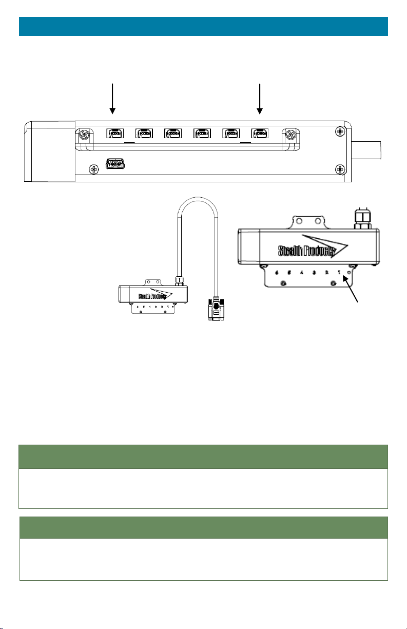
Factory Settings 8.3
Port 6
Port 1
Port 1 Right
Port 2 Reverse
Port 3 None
Port 4 Mode
Port 5 Forward
Port 6 Left
Port 1
The i-Drive 4.0 has the capability of taking inputs from mechanical switches,
proximity sensors, fiber optic sensors, joysticks, and Sip & Puff modules. With
the new i-Drive interface, there is the capability of programming the interface
with the associated Advanced Programming Software from your PC, and now
also includes the option to download the i-Drive App and program the interface
directly from your phone via Bluetooth® wireless technology.
NO T ICE
The software will not read correctly if a non Bluetooth® dongle is plugged into a port .
Any dongle plugged into the interface MUST be Bluetooth® .
NO T ICE
All connectors have blue heat shrink on the cord for visual reference and easy
recognition.
2
Page 13

Parts And Accessories 9.0
i-Drive 4.0 Packages Available 9.1
Part Number Description
IDHBT200-1
IDHBT210-1
IDHBT250-1
IDHBT260-1
IDHBT300-1
IDHBT310-1
IDHBT350-1
i-Drive Tri-Array Head Support, includes 3 Proximity Sensors,
non-proportional, with egg switch for reset mode change and i-Drive
Bluetooth® Interface
i-Drive Tri-Array Head Support with Sip & Puff, includes 3 Proximity
Sensors, with egg switch for reset mode and i-Drive Bluetooth® Interface
i-Drive Pediatric Tri-Array Head Support, includes 3 Proximity Sensors,
non-proportional with egg switch for reset mode change and i-Drive
Bluetooth® Interface
i-Drive Pediatric Tri-Array Head Support with Sip & Puff, includes 3
Proximity Sensors, non-proportional, with egg switch for reset mode
change and i-Drive Bluetooth® Interface
i-Drive Pro Series Head Support, includes 3 Proximity Sensors, occipital
pad, swing away hardware for left and right side, 2 spot pads with egg
switch for reset mode change and i-Drive Bluetooth® Interface
i-Drive Pro Series Head Support with Sip & Puff, includes 3 Proximity
Sensors, non-proportional, with egg switch for reset mode change and
i-Drive Bluetooth® Interface
i-Drive Pediatric Pro Series Head Support, includes 3 Proximity Sensors,
non-proportional, with egg switch for reset mode change and
i-Drive Bluetooth® Interface
IDHBT360-1
i-Drive Pediatric Pro Series Head Array with Sip & Puff, includes 3
Proximity Sensors, non-proportional, with egg switch for reset mode
change and i-Drive Bluetooth® Interface
Replacement/Additional Parts Available 9.2
Part Number Description
IDHBT500-17MM* i-Drive Bluetooth® Interface for 17mm Ball Mount
IDHBT500-1* i-Drive Bluetooth® Interface for 1” Ball Mount
IDHBT500* i-Drive Bluetooth
* These packages include 2 mono plug dongles
®
Interface
3
Page 14
R-Net™ Installation 10.0
The i-Drive plugs into the 9 pin port on the power chair’s control interface. The
location of the port depends on the manufacturer of the interface. Follow the
instructions for your interface manufacturer in these next sections.
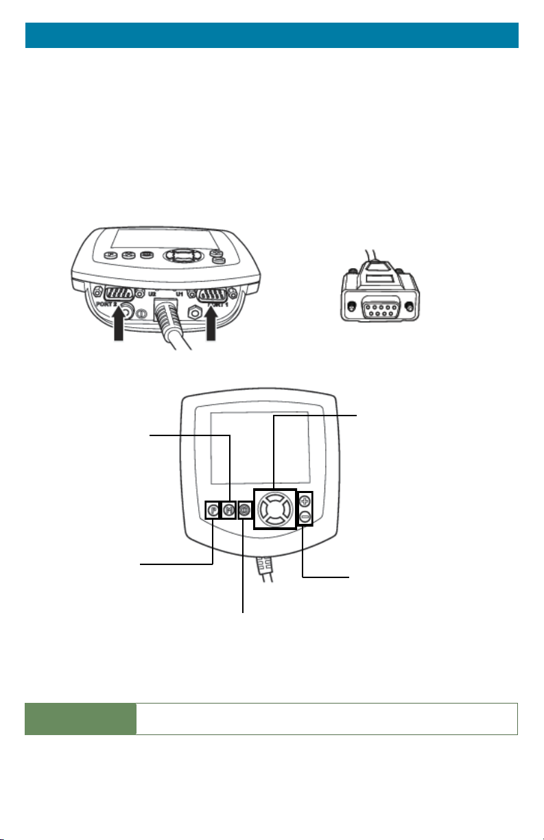
R-Net™ Omni Setup 10.1
Navigation
Mode
Switch mode to drive, power
seating, or OBP (onboard
programming)
Up & Down button to navigate
the menus, Right button to
open a menu item and Left
button to return to previous
menu.
Profile
Switch between preset
drive profiles and activate
device as control.
N O TIC E
4
Plus & Minus
Toggle settings or changes
Power
Turns chair ON/OFF.
An R-Net™ Programming Dongle is required.
value of the highlighted
parameter.
Page 15

R-Net™ Installation 10.0
Setup
1. Power o the chair with the power buon on the joysck or display.
D A NGE R
2. Connect the R-NET programming dongle into the system.
3. Ensure all the cords for the display are properly connected to the chair.
4. Connect i-Drive Alternave Control into Port 1 or Port 2 on the boom of the display
with 9 pin connector.
5. With the chair powered o, open up the app on a Bluetooth enabled device and log in using
the email and password provided to you. Power the chair on and connect to the
applicaon.
6. Press the Mode ‘M’ buon unl you enter the OBP menu.
7. In the OBP menu, navigate with the Up & Down buons to the Omni menu opon and
select with the Right buon.
8. In the Omni menu, navigate with the Up & Down buons to Global on the menu and
select with the Right buon.
9. In the Global menu, navigate with the Up & Down buons to Sleep 12V then toggle to On
with the Right buon.
10. Press the Le buon unl you return to the Omni menu.
11. In the Omni menu, navigate with the Up & Down buons to Proled and select with the
Right buon.
12. In the Omni menu, navigate to the port you have the i-Drive connected to (Port 1 or Port 2).
13. In the Port menu, navigate with the Up & Down buons to SID, toggle to Prp, and with
the Right buon, select. For 3 switch head array applicaons, set SID to 3-Prp.
14. Press the Le buon to back out of the OBP menu. Scroll down to Systems and select
with the Right buon.
15. Scroll down to Joysck Calibraon and with the Right buon, select. Aer you select
Joysck Calibraon, toggle with the Up & Down buons to the port you have the i-Drive
plugged in to. Aer you select, your chair will automacally go in to calibraon mode. The
chair display will ask you to move the chair joysck forward.
16. Go to the i-Drive applicaon on the Phone/Tablet/PC Device. Select Cong Chair tab. Select
Calibrate Chair. Click Okay.
17. Wait unl the calibraon nalizes. Your chair display will show a green checkmark meaning
calibraons was a success.
18. On the Omni display you will need to exit the OBP menu and power the chair o. Now you
will be able to set up the chair as required.
19. Check your conguraon on the Diagnoscs tab. If all is working correctly, your i-Drive is
ready for use. Re-engage your motors.
Disengage the motors before programming the chair.
Ensure your chair is programmed for the port your i-Drive is connected to.
5
Page 16

Q-Logic™ Installation 11.0
Q-Logic™ Setup 11.1
Bookmark Buttons
Select Options in the main menu.
Button actions are displayed on
screen above corresponding
buttons. In other menus, hold
button to Bookmark Settings, and
press button to quickly go to
bookmark.
Navigation
Arrows navigate the main
menu. Up & Down to
navigate the menus, Right
to open a menu item and
Left to return to the
previous menu.
Plus & Minus
Toggle settings or changes values
of the highlighted parameter.
Help Button
Displays information about
options selected on screen.
Q-Logic Enhanced Display
NOTE: Q-Logic™ Enhanced Display and Q-Logic™ Handheld Programmer required.
6
Page 17

Q-Logic™ Installation 11.0
Setup
1. Power o the chair with the power buon on the joysck or display.
D A NGE R
2. Ensure all the cords for the display are properly connected to the chair.
3. Connect the i-Drive Alternave Control into the port on the boom of the display with the
9-pin connector.
4. With the chair powered o, open up the app on a Bluetooth enabled device and log in using
the email and password provided to you. Power the chair on and connect to the
applicaon.
5. Plug in the Q-Logic Programmer to the back of the Q-Logic Display.
6. On the Programmer, select the Program Adjustment opon.
7. In the Program Adjustment menu, navigate with the Up & Down buons to the Specialty
Control opon and with the Right buon,
8. In the Specialty Control menu, navigate with the Up & Down buons to Acve Device and
toggle with the Plus & Minus buons ± to Proporonal Head 3-Direcon.
9. With the Up & Down buons, scroll down to Proporonal Head-3 Direcon folder. With
the Right buon,
10. In the Joysck Setup menu, with the Up & Down buons, scroll down and select
Calibrate. Select Okay.
11. The Q-Logic programmer will read, Roll around joysck in two full circles.
12. Go to the i-Drive applicaon on the Phone/Tablet/PC Device. Select Cong Chair tab. Select
Calibrate Chair. Click Okay.
13. Wait unl the calibraon nalizes, then select Okay with the Q-Logic programmer and
verify the calibraon was successful. (If calibraon was not successful, power o the chair
and repeat Steps 5-12.)
14. Return to the Main Menu and exit the Q-Logic programming.
15. Unplug the Q-Logic handheld programmer.
16. Power chair o.
Disengage the motors before programming the chair.
select.
select and enter folder. Scroll down to Joysck Setup folder and select.
W A RN I NG
Powering off the chair completely before operation is mandatory.
17. The chair is now programmed to recognize the i-Drive. Power the chair back on.
18. Check your conguraon on the diagnoscs tab. If all is working correctly, your i-Drive is
ready for use. Re-engage your motors.
7
Page 18

Q-Logic™ Installation 11.0
Q-Logic™ Drive Control System Further Configuration 11.2
Back Pad Toggle
If you want to disable or enable the back pad’s ability to toggle into forward
and reverse:
1. Reconnect the Q-Logic Handheld Programmer. Follow Steps 1-7 from Setup.
2. On the Q-Logic Programmer, select the Program Adjustments opon.
3. In the Program Adjustments menu, navigate with the Up & Down buons to Specialty
Control, and with the Right buon,
4. In the Specialty Control menu, navigate with the Up & Down buons to Proporonal
Head 3-Direcon, and with the Right buon,
5. In the 3 Switch Head menu, navigate with the Up & Down buons to Back Switch Toggle
and select with the Right navigaon buon.
6. In the Back Switch Toggle menu, navigate with the Up & Down buons to m: Back Toggle
and with the Plus & Minus buons ±, toggle to Enable. This will implement the forward/
reverse toggle with the back pad, or with the Plus & Minus buons ±, toggle to Disable to
disable toggle.
7. Aer conguring the back pad, disconnect the Q-Logic™ Programmer and restart the chair’s
electronics (follow Steps 10-13), or connue to congure other operaons.
Side Pad Toggle/Control
To disable or enable Mode switching with the side pad:
select.
select.
1. Reconnect the Q-Logic Handheld Programmer (follow Steps 1-7 from Setup).
2. On the Q-Logic Programmer, select the Program Adjustments opon.
3. In the Program Adjustments menu, navigate with the Up & Down buons to Specialty
Control and with the Right buon,
4. In the Specialty Control menu, navigate with the Up & Down buons to Proporonal
Head 3-Direcon and with the Right navigaon buon,
5. In the 3 Switch Head menu, navigate with the Up & Down buons to Device Opons/
Timing and select with the Right buon.
6. In the Device Opons/Timing menu, with the Up & Down buons, navigate to m:Device
Double Command and with the Plus & Minus buons ± toggle to Enable. This will set up the
mode switch with the side pad, or with the Plus & Minus buons ± toggle to Disable to
disable the mode switch.
7. Aer conguring the back pad, disconnect the Q-Logic™ Programmer and restart the chair’s
electronics (follow Steps 10-13 from Setup), or connue to congure other operaons.
select.
select.
8
Page 19

Q-Logic™ Installation 11.0
Egg Switch Function
If you would like to change the function of the egg switch to Mode or Toggle
Forward and Reverse:
1. Reconnect the Q-Logic Handheld Programmer (follow Steps 1-7 from Setup).
2. On the Q-Logic Programmer, select Program Adjustments opon.
3. In the Program Adjustments menu, with the Up & Down buons, navigate to Specialty
Control and select with the Right buon.
4. In the Specialty Control menu, navigate with the Up & Down buons to Proporonal
Head 3-Direcon and with the Right buon, select.
5. In the Proporonal Head 3-Direcon menu, navigate to Switch Opons/Timing with the Up
& Down buons and select with the Right buon.
6. In the Switch Opons/Timing menu, navigate with the Up & Down buons to m:Mode
Jack Switch Type and toggle with the Plus & Minus buons ± to Mode to enable mode
switch with the egg switch, or Toggle for forward/reverse toggle.
7. Aer conguring the back pad, disconnect the Q-Logic™ Programmer and restart the
chair’s electronics ( follow Steps 10-13 from Setup) , or connue to congure other
operaons.
9
Page 20

Seating Functions 12.0
Programming Seating Functions 12.1
R-Net
To setup the chair’s seating functions, follow the instructions below:
1. Reconnect the R-Net programming dongle.
2. On the Omni display, enter into the OBP menu.
3. In the OBP menu, navigate with the UP & Down buons and select Omni with the Right
buon.
4. In the Omni menu, select Port 1 or Port 2 with the Right buon.
5. Aer selecng the port, select Controls.
6. Once in the Controls menu, select Actuator Axis and switch to either L/R or R/L.
The left/right pads on the headrest control the seating. One side will toggle
between seat functions while the other side will activate the function and toggle
directions.
Q-Logic
When the option of Proportional Head-3 Direction is chosen during the setup of
the chair, seating functions will automatically default to left/right and the back
pad will be deactivated. By double tapping the left pad, mode settings can be
chosen.
NO T ICE
No further programming will be needed.
10
Page 21

Advanced Programming Software 13.0
i-Drive Advanced Programming Software 13.1
The i-Drive’s Advanced Programming Software is not required to operate the
drive control, but is available to ensure a customized fit and driving experience.
Programming the i-Drive is simple. By connecting a tablet or smartphone and
using the i-Drive Advanced Programming Software application you can:
Dynamic Channel Assignment– any port can control any of the outputs
Adjust Acvaon Proximity– Change the range of moon required for switch acvaon
Provide an adjustable double tap feature that extends chair double tap limits
Conguraon– Programmed by Bluetooth or PC
Getting Started 13.2
The first step to begin use of the i-Drive 4.0 is downloading the software. The
link to download the software is listed on pg. 11. If there are any difficulties
obtaining the software, contact Stealth Products, LLC.
After the software has been installed onto your device, you can begin utilizing
the Advanced Programming Software. Launch the “i-Drive Programmer”
application on your device, and with a USB to Mini-USB cable, connect the
i-Drive to your PC or Tablet. Allow time for the i-Drive to make a full connection
with your computer.
NO T ICE
Sections 12.3 through 12.1.1 will guide you on the setup and configuration
processes on your PC or tablet for the i-Drive.
W A RN I NG
Please manually disengage both drive motors before utilizing the Setup Wizard,
Diagnostics, and Config. If motors are not disengaged, the chair could move
during setup.
11
Page 22

Advanced Programming Software 13.0
Downloading the i-Drive Software 13.3
To program the i-Drive from your PC, the Advanced Programming Software™
will need to be downloaded from the Stealth Products website:
https://stealthproducts.com/idrive/download/
W AR N IN G
To ensure security on your i-Drive, contact Stealth Products to obtain your user
name and password for the software.
12
Page 23

Advanced Programming Software 13.0
Connecting To The i-Drive 13.4
After adequate time is given to allow the i-Drive to connect to your computer
and you have launched the application, click the Connect button.
NO T ICE
If may be required to change the COM in the drop-down menu next to the
Connect button.
NO T ICE
When the i-Drive is connected to the software, the serial number of the
interface, the firmware version of the software, and the system voltage should
appear on the bottom of the screen.
13
Page 24

Advanced Programming Software 13.0
Running The Setup Wizard 13.5
The Setup Wizard will guide you through the initial configuration and channel
assignment of the i-Drive. To begin the Setup Wizard, click the Setup Wizard
button on the left of the screen.
Setup Wizard Feature
The Setup Wizard will guide you through the initial port configuration and
channel assignment of the i-Drive. A window will pop-up on the screen and walk
you through a 7 step setup process. Follow the instructions on the screen or
push Cancel to quit the setup.
14
Page 25

Advanced Programming Software 13.0
i-Drive Configuration Settings 13.6
To begin the configuration, click the Config Mode button on the left of the
screen.
Conguration Feature
Configuration allows you to adjust the way the i-Drive activates and allows you
to fine tune the function and sensitivity of the sensor/joystick/chair.
A
A. Sensor Channels Tab– Navigates to the Sensor Channels menu
B. Double Tap Settings Tab– Navigates to the Double Tap Settings menu
C. Reboot Device Button– Reboots the i-Drive
D. Factory Reset Button– Resets all settings to factory default
E. Save Settings Button– Saves your settings
B
C
D
E
15
Page 26

Advanced Programming Software 13.0
Configuration: Sensor Channels 13.7
1-Diagram shows channel switches and channels currently in use
2-Drop down menus that allow you to assign function to each channel
3-Channel Deadband slider that allows sensitivity change of deadband
4-Changes the channel of which the deadband has been adjusted
NO T ICE
Channels that are not being used will appear in red on the screen.
Be sure to save your settings with the Save Settings button after all the desired
changes have been made.
NO T ICE
1
16
2
3
4
Page 27

Advanced Programming Software 13.0
Configuration: Double Tap Settings 13.8
A. Double Tap-Enabling Double Tap allows for adjustment of Double Tap input
and output timing
B. Double Tap Input Delay– Amount of time for Double Tap command capture
C. Double Tap Output Speed– Time period between Mode output pulses. This
value should match the Double Tap Input Timing of the chair
A
B
C
NO T ICE
It is recommended to use Calibrate Double Tap option in the Diagnostics to get
a properly timed double tap setting for the user.
17
Page 28

Advanced Programming Software 13.0
Running Real Time Diagnostics 13.9
To begin the Diagnostics, click the Diagnostics button on the left of the screen.
A. Mode Switch activation
B. Left, Right, Forward & Reverse activation
C. Corresponding i-Drive port when switch is pressed
D. Double Tap Calibration
Diagnostics Feature
With real time Diagnostics, you are able to observe pad behavior as the head
array is activated by the user. This is useful to fine tune the i-Drive and confirm
it is operating properly.
D
A
B
C
C A UT I ON
Double Tap needs to be enabled in the Configuration menu Double Tap Settings
before Double Tap Calibration can be used.
18
Page 29

Advanced Programming Software 13.0
Help Feature 13.1.0
Clicking the Help button will activate help. When Help is active, the help button
will be green and a question mark (?) will be displayed next to your cursor. With
Help active, clicking buttons and menu items will pop up with an explanation of
what the clicked object is and how it can be utilized. To disable Help, click on
the Help button again.
NO T ICE
The Help button will appear black when inactive and green when active.
19
Page 30

Advanced Programming Software 13.0
Closing the i-Drive Programming Software 13.1.1
When you are finished configuring the i-Drive, you can click on the Quit button
on the bottom right of the screen to close the application.
20
Page 31

i-Drive Mobile App Installation 14.0
Downloading the i-Drive Bluetooth® Application 14.1
For iPhone® Users:
Search, “Trident Research, LLC” in the Apple® App Store®
Install the App and then “Open” once App has been successfully installed on your phone.
21
Page 32

i-Drive Mobile App Installation 14.0
For Android Users:
Search “Trident Research, LLC” in the Play Store
Select “Install” and then “Open” when the App has been successfully installed on your
phone.
22
Page 33

i-Drive Mobile App Installation 14.0
Opening the i-Drive App 14.2
A baery, baery charger, dongle cable, and a 9-pin pig tail plugged into the USB port on
the interface is required in order to connect the i-Drive to your phone.
1. To Log In, enter the User Name and Password assigned to you.
2. When the Main Menu appears, Connect to the i-Drive device (Figure 1).
3. Your Bluetooth® device will search for the i-Drive device.
4. When you have successfully logged in and the App has located the i-Drive device, new
opons will appear in the Main Menu: Cong Mode, Diagnoscs, and About (Figure 2).
NO T ICE
Ensure your phone or wireless device has the Bluetooth® option turned on.
Figure 1 Figure 2
23
Page 34

i-Drive Mobile App Installation 14.0
Config Mode 14.3
1. In the Main Menu, Select Cong Mode (Figure 3). Like the Advanced Programming Soware
on your PC or tablet, channel assignments, double tap sengs, and other sensor sengs
are adjusted here.
2. Under the Name secon, you have the opon of renaming your i-Drive. Changing the name
of your i-Drive will require a power cycle.
Channel Assignment
Figure 3
1. Select the Channels tab under the Cong Mode opon in the App (Figure 4).
2. The Channels tab view shows the standard channel assignments on the i-Drive device, and
any channels that are disconnected from the device.
3. To assign a funcon to each channel, select the channel you are wishing to modify.
24
Figure 4
Page 35

i-Drive Mobile App Installation 14.0
Channel Assignment Settings
1. Within the channel opon chosen, you will see a list of modicaons and assignments that
can be made to the channel.
2. To select the assignment for the channel, click on the assignment. To go back to the
channel opons, click back on the upper le hand corner.
3. Under the Sensor Sengs header, the sensivity of the sensor connected to the device can
be adjusted. Slide your nger to the le or to the right to increase or decrease the
sensivity.
4. Aer channel assignments have been made, in the Channels tab, all of the selecons will
appear to the right of the channel they have been assigned to (Figure 6). If the channels are
to the correct assignments, select Save in the top right hand corner.
5. Select back in the top le hand corner to go back to the Main Menu.
Figure 5
Figure 6
25
Page 36

i-Drive Mobile App Installation 14.0
Multi-Tap Setting
1. To acvate the Mul-Tap funcon, select Mul-Tap in the Cong Mode menu.
2. Under the Mul-Tap seng, Input Delay and Output Speed can be adjusted. Move the
cursor to the right or le to make adjustments. (Figure 7)
3. When adjustments have been made, select the Save opon in the upper right hand corner.
26
Figure 7
Page 37

i-Drive Mobile App Installation 14.0
Diagnostics
1. Aer channel assignments and any other modicaons necessary have been made, go
back to the Main Menu.
2. Select Diagnoscs in the Main Menu.
3. Test the assignments on your i-Drive device by acvang each channel. When the direcon
assigned to the channel has been acvated, the direcon should light up in green.
(Figure 8)
4. Aer the diagnoscs have been tested, select back in the top le hand corner to go back to
the Main Menu.
5. Aer all updates to the interface have been made, exit the App.
Figure 8
27
Page 38

Testing 15.0
After the installation of the i-Drive, execute the following tests before the
wheelchair is delivered or put into service:
Operaonal Test
Test Drive
Stop Test
Operational Test 15.1
W A RN I NG
Execute this test only on a level surface, in an open area free of obstacles.
1. Acvate the wheelchair operang system.
2. Check for any error messages.
3. Apply pressure to the head pad/sensor/joysck, etc. designated for moving the chair in a
forward moon unl you hear the parking breaks switch o.
C A UT I ON
4. Immediately release the pressure from the head pad/sensor/joysck, etc. You should hear
the parking break react within a few seconds.
5. Repeat Steps 3 & 4 three mes, while carefully applying pressure to the device.
6. Check whether the double tap features funcon properly.
The wheelchair may start moving.
Test Drive 15.2
Perform a test drive with the wheelchair.
Check whether the wheelchair and all of its operaons are fully funconing.
Check that no cabling or parts may get damaged or hindered in any possible posion
of the wheelchair.
Stop Test 15.3
Drive full speed ahead and shut o the wheelchair.
The wheelchair may not suddenly stop, but must slow down to a gradual stop.
28
Page 39

First Time Use 16.0
Dealer Assistance 16.1
During first time use by the client, it is advised that the dealer or service
technician assists and explains the different drive configurations to the
customer (the user and/or the attendant). If needed, the dealer can make
final adjustments.
User Testing 16.2
It is important that the customer is fully aware of the installation of the i-Drive,
how to use it, and what settings in the software or App can be adjusted in order
to gain as much mobility as possible. As a dealer, proceed as follows:
Explain and show the customer how you have executed the installaon, and explain
the funcons that have been assigned to the device.
Have the user test all configurations of the device:
Is the device being used by the client within easy reach and in an opmal posion for the
user?
Can the user safely operate the wheelchair with minimal eort?
Conditions Of Use 16.3
The i-Drive 4.0 with Bluetooth® wireless technology is intended for use as
installed by the dealer, in accordance to the installation instructions in this
manual.
The foreseen condions of use are communicated by the dealer or service technician
to the user and/or aendant during the rst me use.
If the condions of use change signicantly, please contact your dealer or a qualied
service technician to avoid excessive wear and tear or unintended damage.
C A UT I ON
These products are designed to be fitted, applied, and installed exclusively by a
health care professional trained for these purposes. The fitting, application and
installation by a non-qualified individual could result in serious injury.
29
Page 40

Maintenance 17.0
Care And Maintenance 17.1
Ensure the hardware you are using stays in working order by keeping it cared
for and maintained.
Keep electronics dry and out of the water.
W A RN I NG
Getting electronics wet will cause irreversible damage to the circuitry.
Periodically check the hardware for looses screws or worn parts. Replace or repair the parts
as needed.
To clean the aluminum, use a mild, nonabrasive household cleaner.
To wash covers, removed the cover from the pad, machine wash cold on a delicate cycle
and drip dry aerwards.
On the hardware, lightly ghten set screws unl they are snug, then ghten an extra
quarter turn.
W A RN I NG
Do no overtighten set screws. Over tightening set screws will prevent
hardware from functioning properly and could cause irreversible damage
to the hardware.
Safety 17.2
Avoid getting electronics wet and working on electronics with wet or damp
hands. This could cause minor to severe electrocution, resulting in personal
injury and/or product damage.
Technical Data 17.3
The i-Drive Bluetooth Interface was tested and found to be in compliance with
the required criteria and met the standards of IEC60601-1-2:2014 (Edition 4.0);
RESNA WC-2:2009.
30
Page 41

Notes 18.0
31
Page 42

Notes 18.0
32
Page 43

Notes 18.0
33
Page 44

Stealth Products, LLC. • info@stealthproducts.com • www.stealthproducts.com
+1(800) 965-9229 | +1(512) 715-9995 | 104 John Kelly Drive, Burnet TX 78611
P137D434R2 Revision Date 2017-03-28
 Loading...