

St. Croix York, York Insert Operation Manual
York Insert
Operation & Maintenance
Manual
Table of Contents
ST. CROIX FEATURES.......................................................................................2
INSTALLATION.................................................................................................. 3
PREVENTING CHIMNEY FIRES .....................................................................3
SATISFACTORY PERFORMANCE................................................................. 3
Pellet Fuel ...............................................................................................................3
Add Corn to the Mix..............................................................................................3
OPERATING INSTRUCTIONS......................................................................... 3
Control Board Features.............................................................................4
Thermostat Function – How does it work?.............................................5
Pre-Lighting Instructions..........................................................................6
Lighting Your Stove ................................................................................. 6
Shutting the Stove off ............................................................................... 6
Diagnostic Features....................................................................................6
Safety Features...........................................................................................7
Combustion Air Damper ...................................................................... 7-8
Flame Pattern Characteristics..................................................................8
MAINTAINING THE STOVE ............................................................................9
Daily Maintenance ........................................................................... 10-11
Periodic Maintenance ...................................................................... 11-13
Yearly Maintenance ......................................................................... 13-14
SAFE OPERATION........................................................................................... 14
TROUBLESHOOTING AND FAQ............................................................ 15-19
PARTS LAYOUT ..........................................................................................20-22
WARRANTY....................................................................................................... 23
1205

Dear St. Croix Pellet Insert Owner:
Congratulations! Your purchase of a St. Croix pellet insert places you among a select
group of individuals who have demonstrated their concern about residential heating
efficiency and our environment.
This owner's manual is designed to help you obtain maximum benefit from your St. Croix
wood pellet stove.
Please read this manual in its entirety BEFORE operating your pellet stove. During the
manufacturing process every effort has been expended to ensure that each St. Croix pellet
insert meets the highest quality standards of material and workmanship.
Here are some important aspects of pellet insert installation and operation, which you
must observe in order to obtain maximum comfort and safety from your new St. Croix
wood pellet stove.
1. Have your new St. Croix pellet insert installed by trained, qualified personnel.
2. Use only clean, dry quality wood pellets that are known to burn satisfactorily in your
stove.
3. Faithfully adhere to the maintenance program described in this manual. Thank you
for selecting a St. Croix pellet insert as the environmentally preferred answer to your
residential heating needs.
SAVE THIS OPERATIONS AND
MAINTENANCE MANUAL
York Operations Manual
Page 1
y
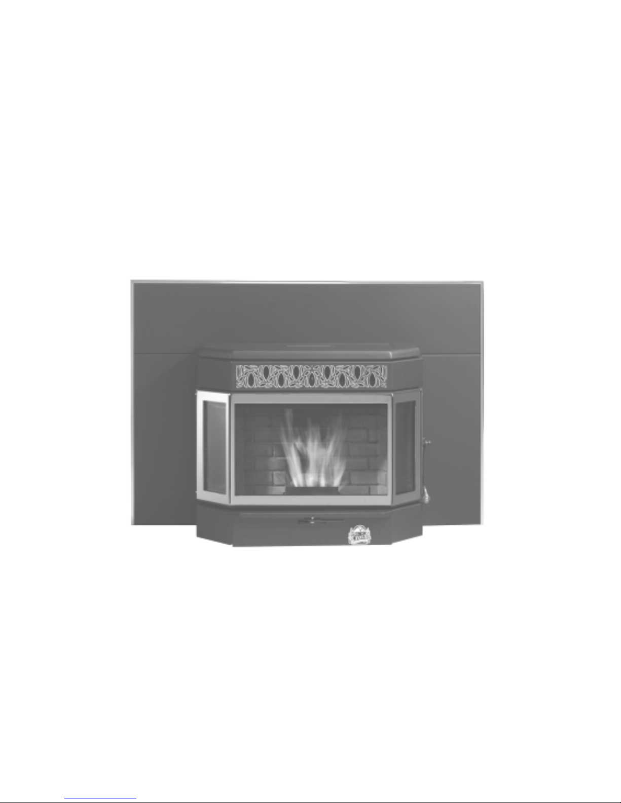
York Insert
Bay Front Pellet Insert
Features:
45 Lbs. Hopper
Tube
Scraper
Rod
Large
Viewing
Glass
With
Air
Wash
System
3 Tray Ash Pan System
Quick Release Latch
with
Digital
Control Board
With
Diagnostic
Features
Exclusive
“SmartStat”
Full
Automatic
Auto Ignite
System
Versa Grate
System
York Operations Manual
Page 2

Operation and Maintenance
York Insert Pellet Stove
CAUTION: Operate this unit only with the fuel hopper lid closed. Failure to do so may result in emission
of products of combustion from the hopper under certain conditions. Maintain hopper seal in good
condition.
INSTALLATION
Proper installation is essential for safety, effective
operation, warranty coverage, and insurance
requirements and to meet local building codes.
Installation requirements are described in the
Installation Manual included with your new
stove.
PREVENTING CHIMNEY FIRES
Chimney fires can be prevented by properly
operating the stove and by periodic inspection
and cleaning of the chimney. When wood is
burned it produces tar and other organic vapors,
which combine with expelled moisture to form
creosote. The creosote vapors condense in the
relatively cool chimney flue associated with a
slow burning fire. As a result, creosote residue
accumulates on the flue lining. When ignited this
creosote can result in an extremely hot chimney
fire.
The chimney and chimney connector should be
inspected at least once every two months during
the heating season to determine if a creosote
build-up has occurred. If a significant layer of
creosote has accumulated (3 mm or more) it
should be removed to reduce the risk of a
chimney fire. Use of an appropriately sized
chimney brush or the services of a professional
chimney sweep are recommended.
SATISFACTORY PERFORMANCE
The keys to satisfactory performance are: proper
operation of the stove, diligent maintenance and
burning only dry, clean, quality wood pellets.
PELLETS
Clinkers and ash are a by-product of pellet
combustion and are not caused solely by your
stove. Stove performance can be quickly and
severely reduced if poor quality pellets are used.
Contact your dealer for more information on APFI
approved wood pellet fuels.
NOTE: Pellets with excessive sawdust should be
screened by sifting with 1/4" mesh screening.
Store Pellets under cover on a wooden pallet or other
methods to ensure they do not become rain soaked
or absorb moisture from damp or wet floors. Do not
store pellets within stove installation clearances or
within the space required for ash removal.
The stove is not warranted against damage caused by
poor pellets, incorrect operation, poor maintenance
or incorrect installation.
ADD CORN TO THE MIX
The Prescott Series is approved to burn a mixture of
pellets and corn (maximum 50% corn). The
Thermostat Switch should be set to the Manual
position. (See Fig. 2 on page 5) Operation of the
stove doesn’t change when burning a mixture of
pellets and corn. The burn pot will need to be
cleaned on a daily basis, using the “Pot Scraper
Tool” shown in figure 5 on page 9. Use the Pot
Scraper Tool to remove any clinkers that build up
because of the corn when needed. For more
information, read the Daily, Periodic and Yearly
Maintenance section towards the back of this
manual.
OPERATING INSTRUCTIONS
A different type of heater. The pellet stove is neither
a cord wood stove nor a furnace. Its operation and
maintenance differ from the traditional wood stove.
FOLLOW THESE OPERATING INSTRUCTIONS
EXACTLY AS STATED TO ENSURE SAFE AND
RELIABLE OPERATION.
1. Carefully read this “Operation and Maintenance”
manual in its entirety BEFORE lighting your stove
for the first time.
2. Obtain final inspection and approval of
installation from local building officials.
York Operations Manual
Page 3

3. Carefully clean all marks off the gold plated
parts before the first fire is lighted. Use a soft
cloth and a “Windex” type cleaner. Caution:
Never use an abrasive cleaner on any plated or
painted parts of the stove.
4. Have your dealer demonstrate all the operational and maintenance steps necessary for proper
use of the stove. Sign and return the warranty
card, to the address listed on the back page.
5. Some odors may be given off during the first
few hours of burning during initial break-in.
These odors are normal and not harmful.
However, ventilating the room until the odors
disappear is recommended.
6. The stove will become HOT while in
operation. Keep children, clothing and furniture
away from all stove surfaces. WARNING: Direct
contact with the stove while operating may
cause skin burns.
7. To avoid the possibility of smoke and/or sparks
entering the room always keep firebox and deashing doors closed whenever the stove is
operating.
8. A certain amount of carbon monoxide may be
produced within the stove as a by-product of
combustion. All exhaust vent connections must
be sealed with RTV silicone to assure a gas tight
seal. Any leaks into a confined area caused by
faulty installation or improper operation of the
stove could produce dizziness, nausea and in
extreme cases, death.
9. An outside source of combustion air is required
on all mobile home installations. If room air is
used to supply combustion air, room air
starvation, operation of exhaust fans and icing of
air vents can adversely affect proper stove
operation. If these conditions exist, outside air
should be used.
10. Smoke detectors, installed in the same general
area as the stove, may be activated if the stove
door is left open and smoke is allowed to enter
the area.
Control Board Features
READ “FREQUENTLY ASKED QUESTIONS”
ON PAGES 15-19 BEFORE OPERATING THE
STOVE.
The Control Board controls all functions of the Stove by
monitoring sensors that are in the system. These sensors
serve 2 purposes.
a. General Operation of the Stove.
b. Safety Features, to shut the unit down in the
event the sensors detect a problem in the unit.
The Control Board also has Diagnostic Capabilities to
help in diagnosing 3 areas in the Stove. These areas are:
1. High Temperature Limit.
2. Proof of Fire Sensor
3. Vacuum in the Firebox
A closer look at the Control Board on page 5, figure 2
will explain how the board works. There are five buttons
labeled 1 through 5, a slide switch labeled 6 and a LED
Light bar with 5 Heat Settings. The LED Light bar is also
used during the Diagnostic process, see page 6 and 7
for more details.
The buttons on the board function as follows: (Refer to
Figure 2. The touch pad buttons and Slide Switch are
labeled with the white numbers 1 through 6)
1. The Heat Level button (1) will advance the
setting between level 1 and 5. Once you reach level
5, it will drop back to level 1. Each level has a LED
light to indicate where the board is set.
2. The On/Off button (2) turns the Stove On and
Off. It will also reset the board after the board has
sensed a problem and is flashing a Diagnostic code.
3. The auger button (3) will allow the customer to
manually auger pellets into the burn pot on start up
when needed. This is particularly helpful in priming
the Auger Tube when it is empty
4. The Draft Trim button (4) allows for
adjusting the Exhaust fan voltage on Heat Level 1
only. Push the button and the all of the LED Lights
in the light bar will flash once. This decreases the
Exhaust fan voltage approximately 5 volts below the
default setting. Push the button a second time and all
of the LED Lights in the light bar will flash twice.
This decreases the voltage approximately another 5
volts. Pushing the button a 3
rd
time will reset the
voltage to the default setting. This adjustment is
available to fine tune the #1 Heat Level draft
setting only. This would only be used in the case the
Stove was hooked up to a tall Vertical Chimney (see
point 9 on page 18 for more information)
York Operations Manual
Page 4
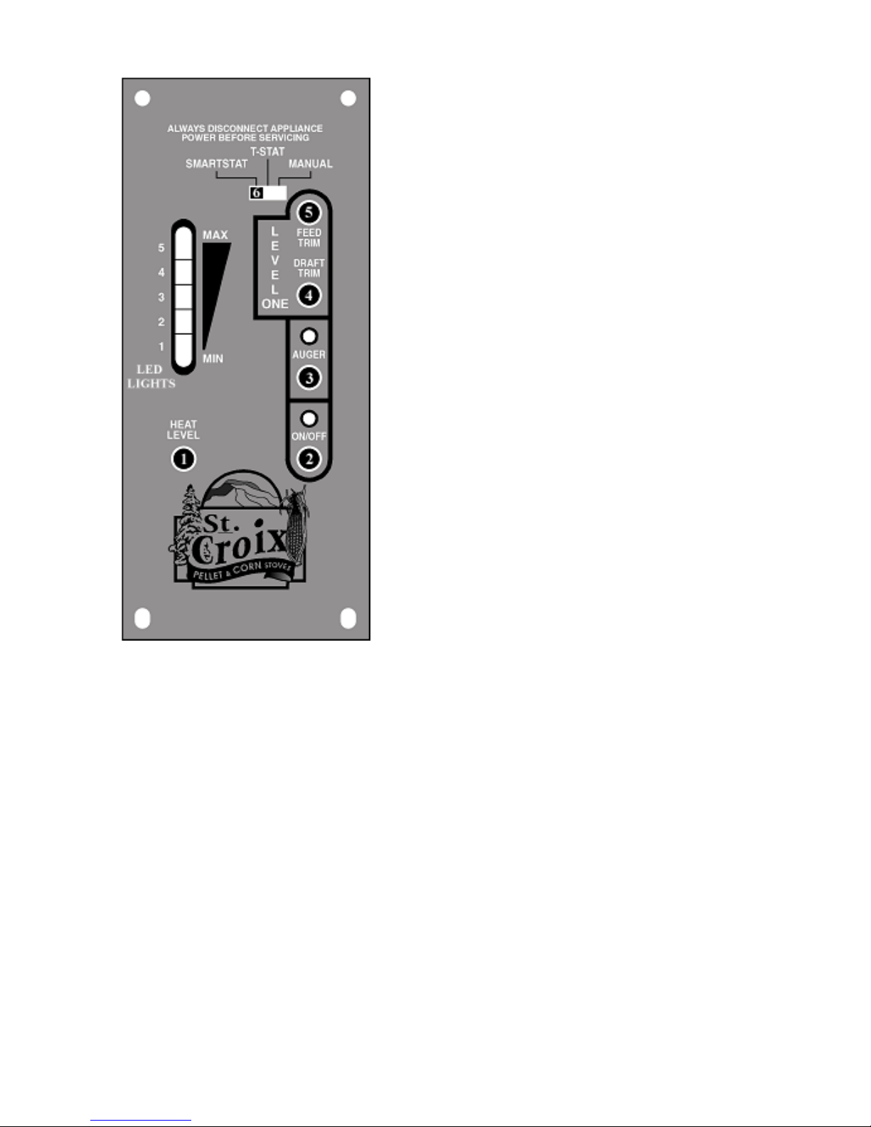
Figure 2
5. The Feed Trim button (5) will allow the Fuel
feed rate to be adjusted on Heat Level 1 only.
Heat Level 1 should be seen as the Pilot setting of
the Stove, when operating on a Thermostat.
Pushing the Feed Trim button (5) will switch
between the different adjustments. Heat Level
one can be adjusted in the following ways:
a. The first LED only indicates the Normal
#1 setting. (1.5 second on time). This is
the default setting.
b. The first and fourth LED lights indicate
the #1 Low setting. (1.25 second on time)
This will reduce the heat output on the #1
setting. This setting will also create more
buildup on the glass. (See point 9 on page
18)
York Operations Manual
c. The first and fifth LED lights indicate the #1
High setting. (1.75 second on time) This
will produce the most heat available on the
#1 setting. This is helpful in keeping the
glass a little cleaner when burning on low.
The adjustments described in points 4 and 5
remain in effect as long as the unit is plugged in.
If the unit gets unplugged or if there is a power
failure the settings are lost and the adjustments
would need to be reset.
Thermostat Function – How does it work?
6. Thermostat Slide Switch. Use this switch to
change the Operations mode between a
Manual Mode, T-stat Mode or a fully
Automatic “SmartStat” Mode.
Manual Mode – The stove is controlled by the
control Board and the operator, no thermostat is
involved.
T-Stat Mode – This is where a thermostat controls
the stove, but the stove never shuts down. In this
mode the stove will advance to the Heat Level that
has been selected when the thermostat calls for heat
and drops to the #1 Heat Level and pilots when the
thermostat doesn’t call for heat.
SmartStat Mode – How does it work?
The SmartStat Function on a St. Croix Pellet stove is
the way a St. Croix operates as a Fully Automatic
stove. A stove operating as a Fully Automatic stove
works great when constant heat isn’t needed. The
stove lights when heat is needed and shuts off when
it isn’t needed. However this is not the way to
operate a stove once the Heating Season arrives.
Then a constant source of heat is what you will be
looking for. This is where the “SmartStat” puts the
St. Croix in a different category. The stove operates
on a Thermostat and once the heat demand has been
met the stove will drop into the #1 Heat Level and
pilots there for one hour. If the thermostat doesn’t
call for heat during that one-hour period, the stove
will shut down and wait to re-light itself when the
thermostat calls for heat again. The control board
automatically switches back and forth between a
“Piloting Thermostat System” and a “Fully
Automatic Thermostat System” based on how often
the thermostat calls for heat. This eliminates the On
– Off cycle of an Automatic stove, once the Heating
season arrives.
Page 5

Pre-Lighting Instructions
When lighting your stove for the first time, or any
time you have run out of Pellets, you will need to
fill the hopper. Pellets are fed from the hopper to
the burn pot by an auger. A high torque motor
that is capable of doing SERIOUS harm to
fingers drives the auger. Keep fingers and other
objects away from the auger.
WARNING: The Auger can start at any
time while the stove is running
WARNING: The Ash Pan Door must be in
the latched position during normal
operation.
WARNING: The Firebox Door must be in
the latched position during normal
operation.
Lighting Your Stove. (Refer to Figure 2)
1. Make sure there are pellets in the hopper and
the viewing door and ash pan door are closed.
2. Push the On/Off button on the control board.
(Button #2)
At this point all that needs to be done is to
monitor the burn pot to make sure the stove starts
up properly. Once the On/Off button has been
pushed the Start Up program takes over.
The Start up Program works as follows:
a. The Combustion fan and Room fan come on
at high speed and the control board checks to
make sure the Vacuum switch locks in. (See
Diagnostic features in column to the right.)
b. When the board senses the Vacuum switch
the Combustion fan drops to the #1 setting
and the Room fan shuts off.
c. The Igniter and the Auger come on (the
Auger only runs for 2 minutes). The stove
will typically light in the first 3 - 4 minutes.
After 5 minutes the board checks for “Proof
of Fire” and starts feeding pellets on the #1
setting (See Diagnostic Features in the
column to the right). Once the board senses
P.O.F. the Igniter shuts off and the stove has
started successfully.
d. If the board fails to sense P.O.F. it will repeat
the previous step and continue feeding pellets on
the #1 setting for 5 more minutes.
e. The board will check for P.O.F. one more time.
If the board still fails to sense the Proof of Fire
switch, the stove will go into “Safety shutdown”
(See Diagnostic Features in the column below).
If this happens, repeat steps 1 through 4 from the
section on Lighting Your Stove.
CAUTION: NEVER ADD FIRE STARTER TO
A HOT STOVE.
Shutting The Stove Off (Refer to Figure 2)
1. Press the On/Off switch (2) once; the lights will
go off and the fire will go out in a few minutes. The
board essentially goes into “Safety shutdown”.
2. As long as the Exhaust Temperature within the
stove remains above 110°F, the Room Air Fan, the
Combustion Exhaust Fan and the Versa Grate motor
will continue to run. Once the P.O.F. switch drops
out the Combustion Fan runs for another 10 minutes
and finally the stove shuts down completely.
3. NEVER unplug the stove to shut it off. Doing so
may cause a significant amount of smoke to enter
the room.
Diagnostic Features of the Control Board
The #2 LED and the #3 LED lights on the LED
Light bar as show in Figure 2 will flash to give a
diagnostic code to help in diagnosing problems that
may occur.
These conditions fall into 2 categories:
a. Heat related issues.
b. Vacuum related issues.
The Diagnostic Lights flash as follows:
The Proof of Fire switch. This switch will sense
the temperature of the Exhaust rising during start
up. If the Exhaust temperature does not reach
110 degrees F, or if during use the temperature
drops below 110 degrees F, the Stove will go
into “Internal Alarm” and the Auger will quit
feeding fuel. Once the stove completes the
York Operations Manual
Page 6

y
y
safety shutdown, the #3 LED will start
blinking. (See Figure 2 on Page 5 and point 3
on page 15)
1. The High Limit switch. This sensor will
sense if the unit reaches temperatures that are
too high for normal operation. If this happens
the Auger will quit feeding and the #2 and #3
LED lights will flash simultaneously. (See
Figure 2 on Page 5 and point 4 on page 16)
2. The Vacuum Switch - For the stove to
operate, the Firebox needs to be sealed.
During the first 30 seconds after the stove has
been turned on the Control Board will check
if the switch senses negative pressure
(Vacuum) in the Firebox of the stove. If there
is no negative pressure, the stove will shut
down and the #2 LED will start blinking.
(See Figure 2 on Page 5 and point 2 on page
15).
“Power Reset”. If the board becomes
unresponsive you must unplug the stove, wait 10
seconds and plug the stove back in to reset the
board.
“Internal Alarm”. When the control board
becomes unresponsive, the control board is in
Internal Alarm. The control board has sensed one
of the Safety sensors. This may cause the stove to
go out. In some cases, after waiting
approximately 45 seconds the stove will start
responding to the control board again. Many
times, the cause of this is a change in the vacuum
inside the stove. This may be caused by excessive
wind, opening the Firebox door or opening the
Ash Pan door. The control board will monitor the
vacuum switch and resume normal operation if
the vacuum returns to normal.
Safety Features
1. ”High Limit” switch”, an overheat
safety switch will shut off the fuel feed if the
Stove reaches temperatures above normal
operating temperature. This is a “Normally
Closed” switch and is part of the Fan limit
control. If the High limit switch trips several
times, the problem in the Stove must be
diagnosed before the Stove is put back in
service, (Defective Room Fan, dirty Room
Fan, dirty Return Air Filter, defective Fan
Limit Control or possibly a bad Control
Board)
York Operations Manual
2. Proof of Fire switch also called the P.O.F.
This senses the temperature rise in the exhaust
system. The switch is “Normally Open” and
closes the circuit at 110 degrees. The Stove will
shut down if temperatures above 110 degrees F
are not sensed during start up or if the
temperature drops below 110 degrees during
normal operation.
3. Vacuum switch also called the Negative
pressure switch. When the stove is turned on
the Exhaust fan will create a negative pressure in
the firebox. The control board continually
checks to see if Negative Pressure (vacuum) is
present during operation of the Stove. If the
exhaust venting system becomes clogged or
obstructed, the firebox door or ash pan door are
left open or the exhaust fan quits working the
control board will go into “Safety shutdown”.
There is a 60 second window to allow for
cleaning the glass and removing the clinker
before then Stove shuts down. This is sufficient
for the Daily Maintenance
The St. Croix Pellet Stove has been Safety Tested
by an accredited, independent laboratory.
WARNING: These safety features are
designed to protect life and propert
passing these features voids all warranties
B
and the safety listing of the stove.
Damper Adjustment
When burning pellets make sure to check for the
formation of creosote in the unit and venting
system. Constantly running the stove on a low
setting with too much combustion air may cause
creosote to form. Burn pot temperatures can be
“too cool” when burning on low with too much
draft.
Adjusting the Damper may take a little time and
patience, but only needs to be done once. After the
damper has been adjusted to the venting system in
your home, the control board will do the rest.
The purpose of this damper is to adjust combustion
airflow to match the characteristic of each specific
air inlet and chimney configuration. The damper has
been preset at the factory and is about 80% closed.
This setting will work with most installations. Tall
Page 7
.
 Loading...