

St. Croix Prescott EXP, Prescott EXL Installation Manual

St. Croix
Prescott Series
Installation Manual
Table of Contents
General Information .................................................................................................................. 1
Installation Check List .............................................................................................................. 2
Approved Installations............................................................................................................... 3
Exhaust Venting ............................................................................................................... ......... 4
Venting - Approved Materials .................................................................................... 4
Venting-Typical PL Vent Components........................................................................ 5
Venting - Determining Materials ............................................................................... 6
Venting Stove Outlet Dimensions.............................................................................7-8
Venting: Through Combustibles ................................................................................ 9
Venting: Into an Existing Chimney .......................................................................... 11
Venting: Hearth Mount..............................................................................................12
Venting: Termination Requirements ................................................................... 13-14
Combustion Air ....................................................................................................................... 16
Electrical Connections ............................................................................................................ 17
Floor Protection ...................................................................................................................... 18
Clearances to Combustible Materials ..................................................................................... 19
Mobile Home Installation ....................................................................................................... 21
Thermostat Installation and Operation.......................................................................................23
208
GENERAL INFORMATION
SAFETY PRECAUTIONS
INSTALLATION MANUAL
SAFETY NOTICE: The stove must be properly installed in order to prevent the possibility of a
house fire! These installation instructions must be strictly observed! Failure to follow
instructions may result in property damage, bodily injury or even death.
The stove’s exhaust system works with negative combustion chamber pressure and a slightly
positive chimney pressure. Therefore, it is imperative that the air intake and exhaust system be
airtight and installed correctly. Do not install a flue damper in the exhaust vent of this unit.
Do not connect this unit to a chimney flue serving another appliance or to any air distribution
duct or system.
Contact the local building officials to obtain a permit and information on any local installation
restrictions and inspection requirements.
The word “stove” as used in this manual is interpreted to mean a pellet burning freestanding
stove, insert, or zero-clearance fireplace, unless otherwise noted.
The stove has been independently tested and listed by Warnock Hersey Laboratories in
accordance with the proposed ASTM Standards and the applicable portions of UL 1482 and
ULC S627/B366.2, and Oregon Administrative Rules 814-23-901 through 814-23- 909, stating
requirements for installation as a stove, heater or hearth insert for masonry, metal and zero
clearance fireplaces and for mobile home installations. The safety-listing label is located on the
back of the stove.
DISCLAIMER OF WARRANTY
Since Even Temp Company has no control over the installation of a stove, Even Temp Company
grants no warranty, implied or stated, for the installation of a stove and assumes no responsibility
for any special, incidental or consequential damages.
SAVE THIS
BUILDING PERMIT
DEFINITION OF “STOVE”
SAFETY TESTING
Prescott Series Installation Manual
Page 1

INSTALLATION CHECK LIST
BEFORE INSTALLATION
Thoroughly read and understand this manual. SAVE THIS MANUAL.
Check with local authorities and obtain needed permits
3. It is strongly recommended that the stove receive a Dealer’s “Pre-delivery Check” prior to
installation.
4. We recommend installation by a qualified professional.
BEFORE STARTING THE STOVE FOR THE FIRST TIME
1. Outside combustion air may be recommended for certain installations (negative pressure). Use
only approved parts. Outside air kit # 100354 is available or any comparable components as
listed on page 13.
2. All joints of PL vent and single wall stainless steel pipe should be fastened by at least 3 screws
and correctly installed. (Follow vent manufacturer’s instructions). Seal all joints with high
temperature silicone to create an airtight seal.
3. Any “plated” areas should be cleaned thoroughly with a glass cleaner such as Windex® and a
soft cloth just before lighting the first fire. This will remove fingerprints and oils that may cause
a permanent stain or mark on the gold plating the first time it is heated. Never use an abrasive
cleaner or material on any plated or painted surfaces. Never clean the plated surfaces when stove
is hot.
4. WARNING: The high temperature paint on this stove may take several hours of burning at a
high fuel setting to cure fully. During this time, an odor that is not harmful may be evident.
When odors are present, the area around the stove should be well ventilated.
5. Caution: The high temperature paint can be easily scratched prior to burning the stove.
Prescott Series Installation Manual
Page 2
APPROVED INSTALLATIONS
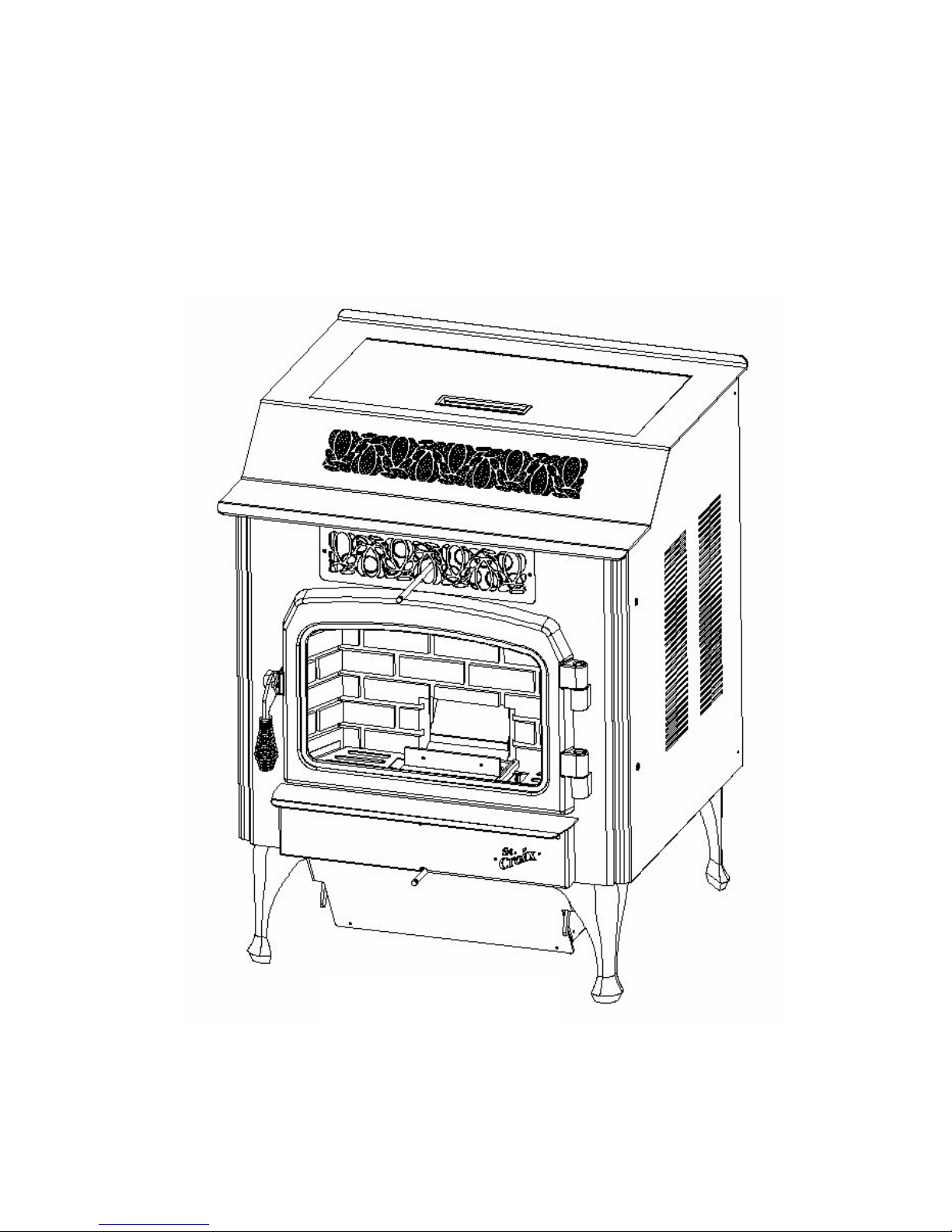
The Prescott EXP and Prescott EXL models are approved for CONVENTIONAL and MOBILE
HOME installations as a FREESTANDING stove. The stoves may also be installed on the
Hearth in front of a fireplace and vented through the chimney of the fireplace.
WARNING: The stove must not be installed in a sleeping room.
Prescott EXL
Prescott Series Installation Manual
Page 3
EXHAUST VENTING
VENTING: APPROVED MA TERIALS
The stove requires a venting system, approved for pellet stoves by a certified testing lab.
Approved pellet stove venting materials are: 1) PL vent, a double wall vent with a stainless steel
liner; and 2) Single wall rigid or flexible stainless steel pipe. PL Vent and Single wall vent is
available through manufacturers such as: Simpson DuraVent, Energy Vent LTD, James A. Ryder
and Selkirk Metalbestos and is carried by many local pellet stove dealers. In this manual
approved venting will be referred to a “PL vent” or “Single wall vent”. All single wall vent
adaptors must be stainless steel.
NOTE: TYPE “B” GAS VENT MUST NOT BE USED IN ANY PELLET STOVE
INSTALLATION.
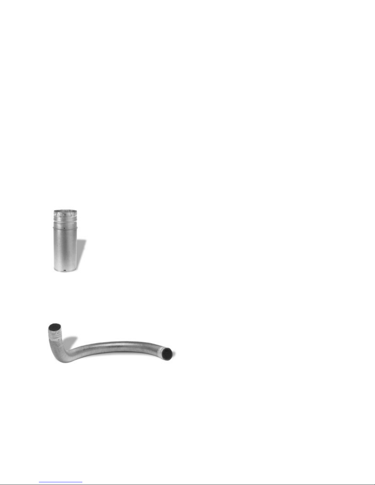
Examples of venting system components follow:
High temperature ceramic roping reduces potential fly ash escaping through joints.
Stainless steel inner liners resist corrosive flue gas damage to the system..
Flex pipe is 430 stainless steel, 4 ply construction with a total thickness of approx. .07 inches.
Prescott Series Installation Manual
Page 4
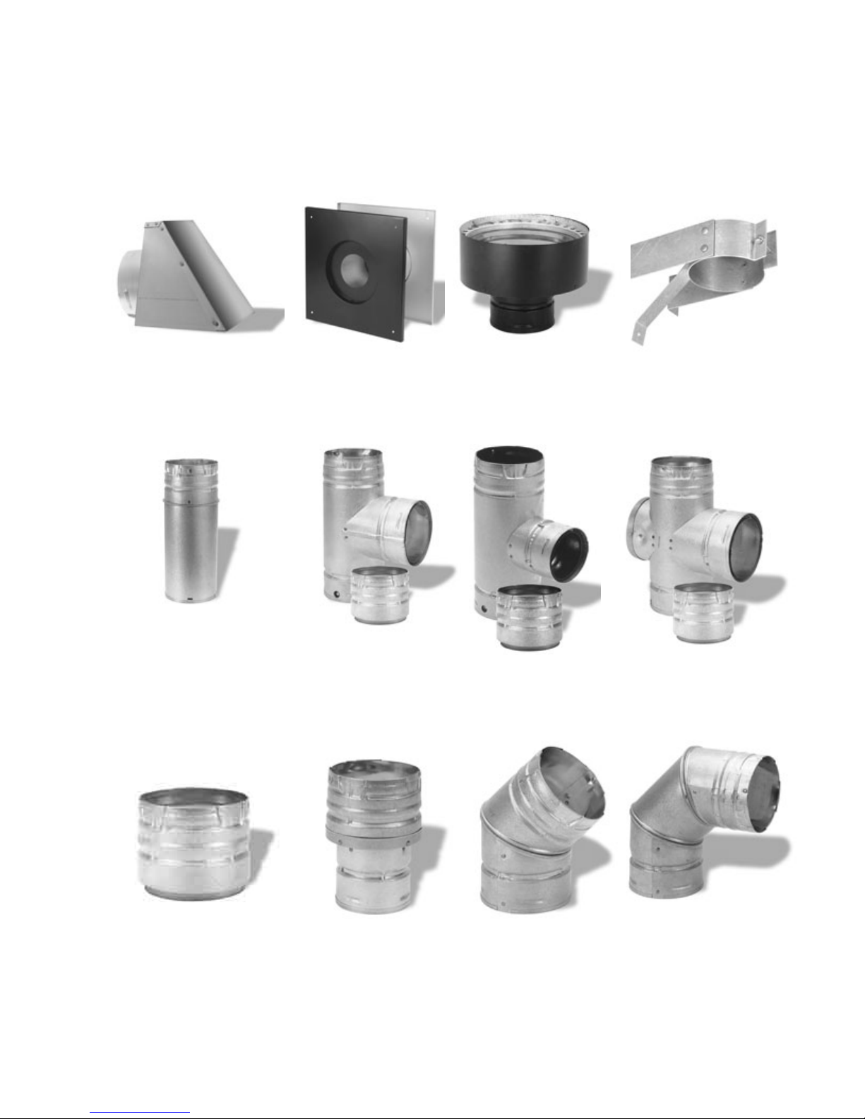
TYPICAL PL VENT COMPONENTS
RAIN CAP
VERTICAL OR WALL THIMBLE CHIMNEY SUPPORT BRACKET
HORIZONTAL ADAPTER
ADJUSTABLE LENGTH SINGLE TEE SINGLE REDUCTION DOUBLE TEE
PIPE w/TEE CAP TEE w/TEE CAP w/TEE CAP
PIPE ADAPTER INCREASER 450 ELBOW 900 ELBOW
Prescott Series Installation Manual
Page 5

VENTING: DETERMINING MATERIALS
TYPE OF MATERIALS:
1. PL Vent must be used for venting all Freestanding stoves.
2. Exception: Single wall stainless steel may be used inside a fireplace or fireplace chimney.
(No clearances to combustibles are needed on single wall stainless steel adaptors, rigid or flex
pipe installed within a fireplace or inside a chimney.)
3. A clean out “tee” (PL Vent or “Quick-Connect Exhaust”) must be installed directly to the
stove and at the bottom of each vertical run of the exhaust system. These tees are to assist in
periodically cleaning the pipe. Single or double clean-out tees may be used. The exhaust system
must be installed so the entire system can be cleaned without disassembly.
NOTE: ADHERE TO THE PL VENT CLEARANCES TO COMBUSTIBLES AS REQUIRED.
STRICTLY OBSERVE THE PL VENT MANUFACTURER’S SAFETY SPECIFICATIONS.
QUANTITY OF MATERIALS:
1. Installing the vent system with a minimum of three feet (3’) of vertical rise above the stove
exhaust port will provide some Natural Draft.
FAILURE TO PROVIDE THE NATURAL DRAFT THAT RESULTS FROM A VERTICAL
RISE MAY RESULT IN SMOKE BEING RELEASED INTO THE HOUSE WHEN
ELECTRICITY TO THE UNIT IS INTERRUPTED WHILE BURNING OR SMOLDERING
PELLETS REMAINS IN THE BURN GRATE.
2. Additional vertical exhaust venting may be needed when using:
a. More than one (1) elbow or tee; and/or
b. Horizontal runs of over three (3) feet.
3. For a venting system ending in a horizontal run, the exhaust pipe must be terminated by a
listed end cap or a PL vent elbow (45 or 90 degrees). Note: End caps or elbows must vent
exhaust gases away from the building.
4. For termination above the building roofline a rain cap is required.
5. The exhaust pipe on all stoves is 2.95” O.D. to accommodate a 3” stove pipe adaptor. Your
installation may require the use of 4” vent. (3” to 4” adapters are available for both PL Vent and
Single Wall Vent.)
Use the following guidelines:
Prescott Series Installation Manual
Page 6
Venting size Guidelines
Type of Installation: Size:______________
A. Less than 10’ horizontal: 3” Acceptable
B. 10’ to 12’ horizontal: 3” or 4” Acceptable
C. Over 12’ horizontal: 4” Required
(A horizontal installation over 12’ is NOT RECOMMENDED)
D. Less than 15’ vertical: 3” Acceptable
E. Over 15’ vertical: 4” Required
F. Above 4000’ elevation: 3” or 4” Acceptable
Note: Four (4) inch vent may be used in all installations. If in doubt, use 4” vent.
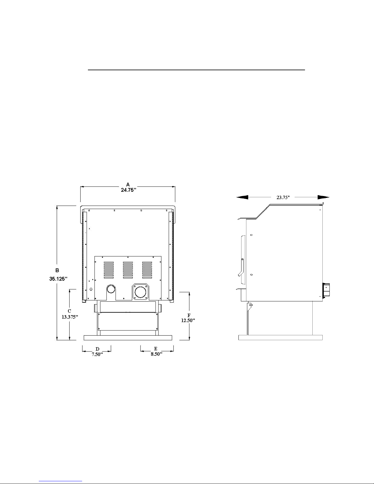
Figure 1. REAR VIEW
A – Width of stove
D – Side of stove to center of intake tube
B – Height of stove
C – Center of intake tube from floor
E – Side of stove to center of exhaust
F – Center of exhaust from floor
Prescott Series Installation Manual
Page 7
 Loading...