

St. Croix Element-MF Installation & Operation Manual
813
inspection requirements in your area.
Installation & Operations Manual
Element-MF
With
SmartScan Maintenance Sensor
Patent Pending
"Please read this entire manual before installation and use of this pellet fuelburning room heater. Failure to follow these instructions could result in
property damage, bodily injury or even death."
"Contact local building or fire officials about restrictions and installation
Save these Instructions
Element-MF Stove
1

TABLE OF CONTENTS
General Information ...................................................................................................... 4
Installation Check List .................................................................................................. 5
Element-MF Layout Diagram..................................................................................... 6-7
Element-MF Dimensions, Location & Clearances ....................................................... 8
Approved Installations .................................................................................................8-9
Exhaust Venting............................................................................................................ 10
Venting - Approved Materials ....................................................................... 10
Venting-Typical PL Vent Components ........................................................... 11
Venting - Determining Materials .................................................................. 12
Venting - Termination Requirements.........................................................13-14
Venting: Termination Clearance Requirements ............................................ 15
Venting – Into an existing Chimney................................................................ 16
Venting – Hearth Mount.................................................................................. 17
Floor Protection .......................................................................................................... 18
Minimum Clearances ............................................................................................. 19-20
Combustion Air Requirements .................................................................................... 21
Mobile Home Installation ........................................................................................22-23
Use of a Thermostat .................................................................................................23-24
Element-MF Operation ................................................................................................. 25
Installation Check .......................................................................................... 25
Preventing Chimney Fires.............................................................................. 25
Element-P Approved Fuels ......................................................................................26-27
Pre-Fire Instructions.................................................................................................27-29
Element-MF Stove
2

Control Board Features ............................................................................................30-32
Shutting Off the Stove .................................................................................................. 32
Diagnostic & Safety Features ..................................................................................33-37
Combustion Air Damper – Location and Adjustments............................................36-39
Thermostat Control & Pilot Settings............................................................................. 39
Element-MF Maintenance ............................................................................................ 40
St. Croix Clinker Theory................................................................................ 40
Clinker/Ash Removal (Multi-Fuel pot) ......................................................... 41
Daily Maintenance (Multi-Fuel Pot)........................................................................42-44
Periodic Maintenance...............................................................................................45-47
Yearly Maintenance .................................................................................................47-48
Safe Operation .............................................................................................................. 49
Wiring Schematic.......................................................................................................... 50
Troubleshooting & Frequently Asked Questions ...............................................51-55
Parts Breakdown (Multi-Fuel Pot & Common parts) ..............................................56-63
Warranty ....................................................................................................................... 64
Element-MF Info & Notes ............................................................................................ 65
Even Temp, Inc.
P.O. Box 127
Waco, NE 68460
EMAIL: support@stcroixstoves.com
WEB ADDRESS: www.stcroixstoves.com
Element-MF Stove
3

Save This Installation & Operations Manual
GENERAL INFORMATION
SAFETY PRECAUTIONS
SAFETY NOTICE: The Element-MF must be properly installed in order to prevent the
possibility of a house fire! These installation instructions must be strictly observed! The
Maintenance schedule must be followed as described in this manual. Failure to follow
instructions may result in property damage, bodily injury or even death.
The Element-MF’s exhaust system works with negative combustion chamber pressure and a
slightly positive chimney pressure. Therefore, it is imperative that the air intake and exhaust
system be airtight and installed correctly. Do not install a flue damper in the exhaust vent of this
unit.
Do not connect this unit to a chimney flue serving another appliance.
CONTACT THE LOCAL BUILDING OFFICIALS TO OBTAIN A PERMIT AND
INFORMATION ON ANY LOCAL INSTALLATION RESTRICTIONS AND
INSPECTION REQUIREMENTS.
DEFINITION OF “MULTI-FUEL STOVE”
The word “Multi-Fuel Stove” as used in this manual is interpreted to mean a corn, wheat, rye
Distillers Grain pellets, Cherry pits or wood pellet burning Multi-Fuel Stove. This model is not
intended as the sole source of heat.
The Element-MF has been independently tested and listed by Warnock Hersey Laboratories in
accordance with the proposed ASTM E 1509-2004 Standards and the applicable portions of UL
1482 and ULC S627/B366.2, and Oregon Administrative Rules 814-23-901 through 814-23909, stating requirements for installation the Element-MF and for mobile home installations. The
safety-listing label is located on the back of the unit. Please refer to label for pertinent
information.
Since Even Temp Company has no control over the installation of the Element-MF, Even Temp
Company grants no warranty, implied or stated, for the installation of the Element-MF and
assumes no responsibility for any special, incidental or consequential damages.
BUILDING PERMIT
SAFETY TESTING
DISCLAIMER OF WARRANTY
MANUFACTURED BY:
Even Temp Inc
Hwy 34
Waco, NE, 68467
Element-MF Stove
4
BEFORE INSTALLATION THOROUGHLY
READ AND UNDERSTAND THIS MANUAL
SAFETY NOTICE
PLEASE READ THE ENTIRE MANUAL BEFORE INSTALLING AND USING YOUR NEW MULTI-FUEL STOVE.
FAILURE TO FOLLOW INSTRUCTIONS MAY RESULT IN POPERTY DAMAGE, BODILY INJURY, OR EVEN
DEATH.
BEFORE STARTING THE MULTI-FUEL STOVE FOR THE FIRST TIME
1. Under certain conditions outside combustion air is recommended. Use only approved parts. When using
out side air for combustion, check that the outside air inlet is connected to draw fresh air from outside the
building.
2. All joints of PL vent and single wall stainless steel pipe should be fastened by at least 3 screws and
correctly installed. (Follow vent manufacturer’s instructions). Seal all joints with high temperature silicone
to create an airtight seal.
3. WARNING: The high temperature paint on this Multi-Fuel Stove may take several hours of burning at a
high fuel setting to cure fully. During this time, an odor that is not harmful may be evident. When odors are
present, the area around the Multi-Fuel Stove should be well ventilated.
4. Caution: The high temperature paint can be easily scratched prior to burning the Multi-Fuel Stove.
CAUTION
FAILURE TO FOLLOW THE INSTRUCTIONS IN THE INSTALLATIONS MANUAL MAY RESULT
IN A HOUSE FIRE. PLEASE FOLLOW INSTALLATION AND MAINTENANCE INSTRUCTIONS.
TABLE OF CONTENTS
CHECK WITH LOCAL AUTHORITIES AND OBTAIN NEEDED PERMITS
WE RECOMMEND INSTALLATION BY A QUALIFIED PROFESSIONAL.
INSTALLATION CHECK LIST
FOR USE IN THE U.S. AND CANADA
MOBILE HOME APPROVED
Element-MF Stove
5
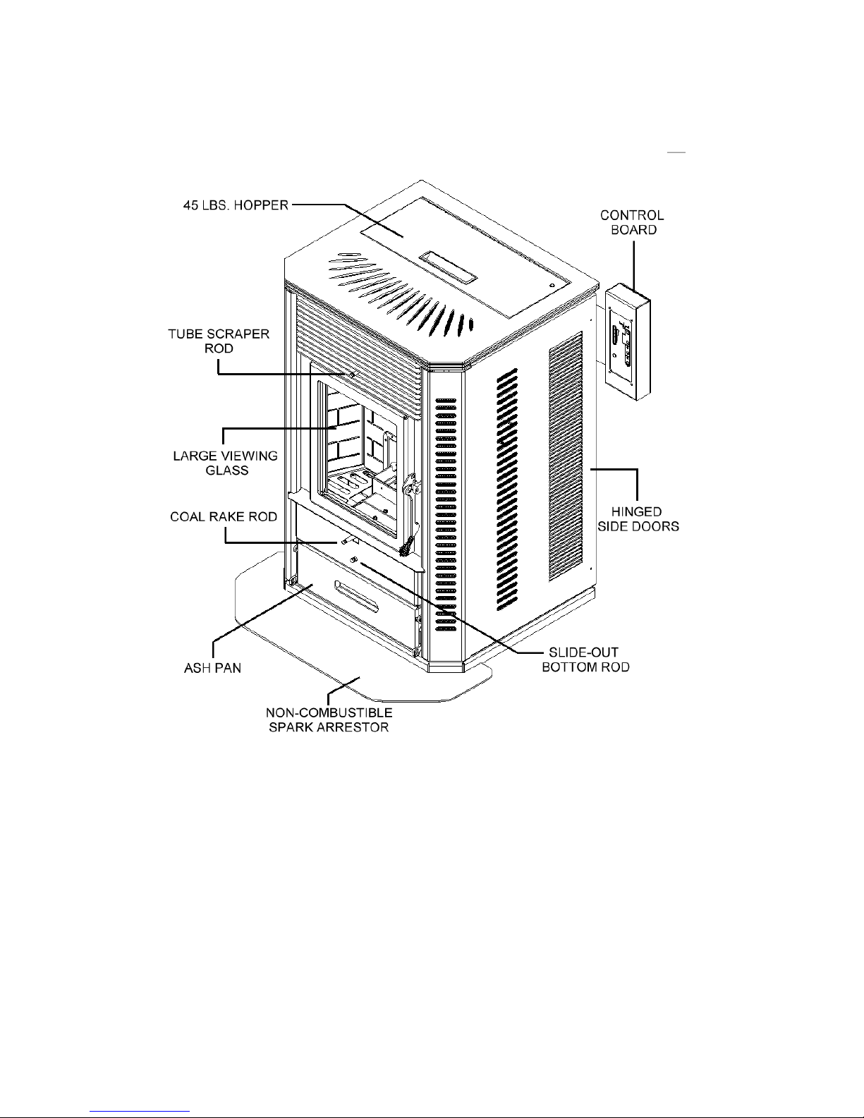
Element-MF
Stove Layout
Figure 1
There are two burn systems used in the Element Series. These systems are interchangeable in the
stove body. This Manual covers the ELEMENT-MF, which uses the Multi-Fuel Burn System
The Multi-Fuel Burn System is the St. Croix Patented “Clinker Removal System”. This burn
pot allows the clinker to be removed without loosing the fire in the pot. This eliminates the need
of having to re-light the Element-MF after removing the clinker. This burn system does not have
Self-Ignition. It is approved for Pellets Corn, Wheat, Rye, Cherry Pits & Distillers Grain Pellets.
Element-MF Stove
6
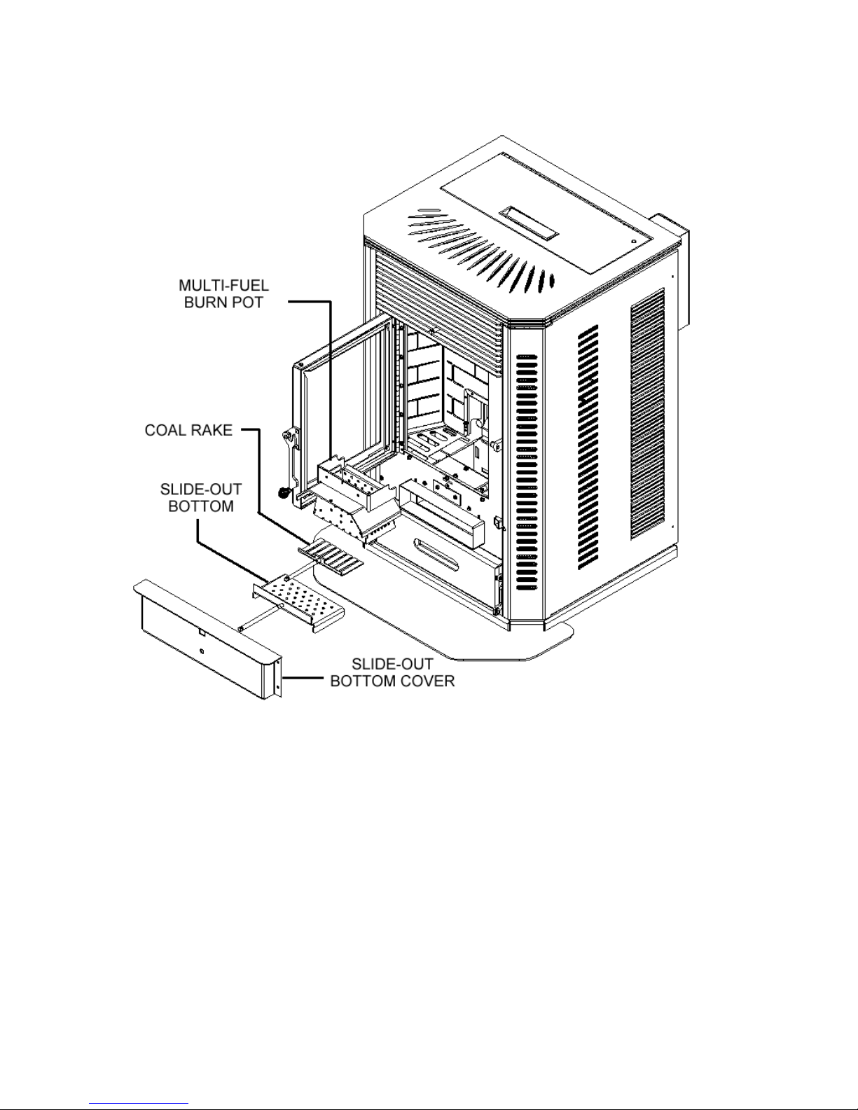
Figure 2
Multi-Fuel Burn System approved with the following Fuels:
Pellets, Corn, Wheat, Rye, Cherry Pits & Distillers Grain Pellets
Element-MF Stove
7
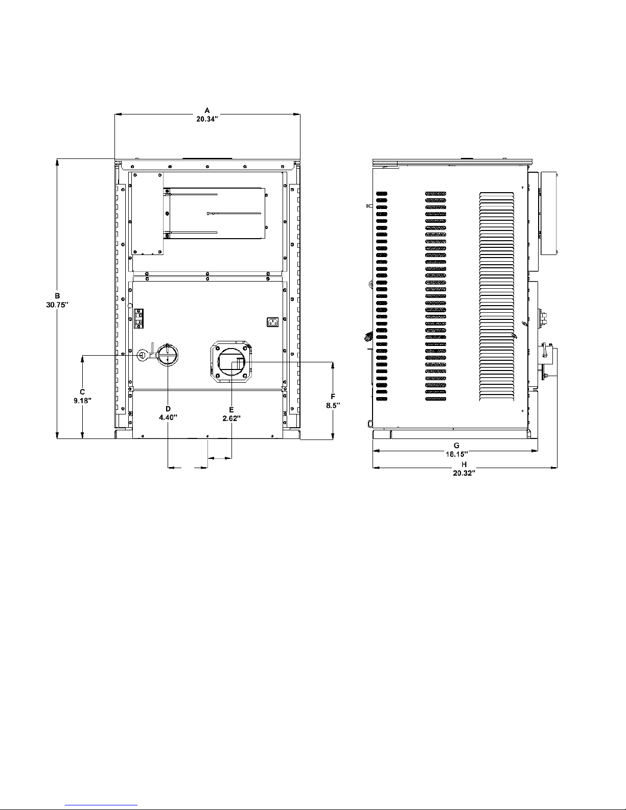
STOVE DIMENSIONS
Figure 3
A - Width of Stove E - Center of stove to center of exhaust
B – Height of Stove F - Center of exhaust from Base of Stove
C – Center of Air Intake from Base of Stove G – Front of Stove to Back of Stove
D - Center of Stove to Center of Air Intake H – Front of Stove to end of Exhaust Pipe
The Element-MF is approved for CONVENTIONAL and MOBILE HOME installations as a
FREESTANDING stove. The stove may also be installed on the Hearth in front of a Fireplace
and vented through the chimney of the fireplace.
Approved Installations
Element-MF Stove
8

Caution
INSTALLATION IS TO BE PERFORMED BY A QUALIFIED INSTALLER OR
DEALER.
ADHERE TO ALL CLEARANCES SPECIFIED BY THE MANUFACTURER OF THE
VENTING SYSTEM.
ADHERE TO ALL CLEARANCES SPECIFIED IN THE INSTALLATION MANUAL
OF THE ELEMENT-MF STOVE.
THE ELEMENT-MF USES A POSITIVE PRESSURE VENT SYSTEM. DO NOT
INSTALL A FLUE DAMPER IN THE EXHAUST SYSTEM OF UNIT
DO NOT CONNECT THE ELEMENT-MF STOVE TO A CHIMNEY SYSTEM THAT IS
CONNECTED TO ANOTHER APPLIANCE.
DO NOT INSTALL THIS UNIT IN A SLEEPING ROOM
ATTENTION
CONDENSATION:
Stove, keep in mind that condensation is detrimental to exhaust systems. Corn,
Wheat, & Rye have higher moisture content than pellets and can be more
susceptible to condensation forming in certain types of installations. Install the
Element-MF with a minimum of the Vent system exposed to the cold
temperatures outside the envelope of the house. Insulate the vent system if in
doubt. Check with the manufacturer of your venting system that they honor the
warranty of their PL Vent with the use of corn.
When planning the installation of your Element-MF
ATTENTION
BATTERY BACKUP: We strongly recommend using a battery backup system if
the Element-MF is installed using horizontal venting only. This prevents any
smoke from entering your home in the event of a power failure. The battery
back-up system must provide “pure sine wave” power to operate the unit.
Element-MF Stove
9
VENTING: APPROVED MATERIALS
The Element-MF requires a venting system approved for pellet or corn venting by a certified
testing lab. Approved pellet or corn venting materials are: 1) PL vent, a double wall vent with a
stainless steel liner; and 2) Single wall rigid or flexible stainless steel pipe. PL Vent and Single
wall vent is available through manufacturers such as: ICC Pellet Vent, Energy Vent LTD, James
A. Ryder, Simpson Dura Vent and Selkirk Metalbestos and is carried by many local dealers. In
this manual approved venting will be referred to a “PL vent” or “Single wall vent”. All single
wall vent adaptors must be stainless steel.
NOTE: TYPE “B” GAS VENT MUST NOT BE USED IN THE INSTALLATION OF THIS
MULTI-FUEL STOVE
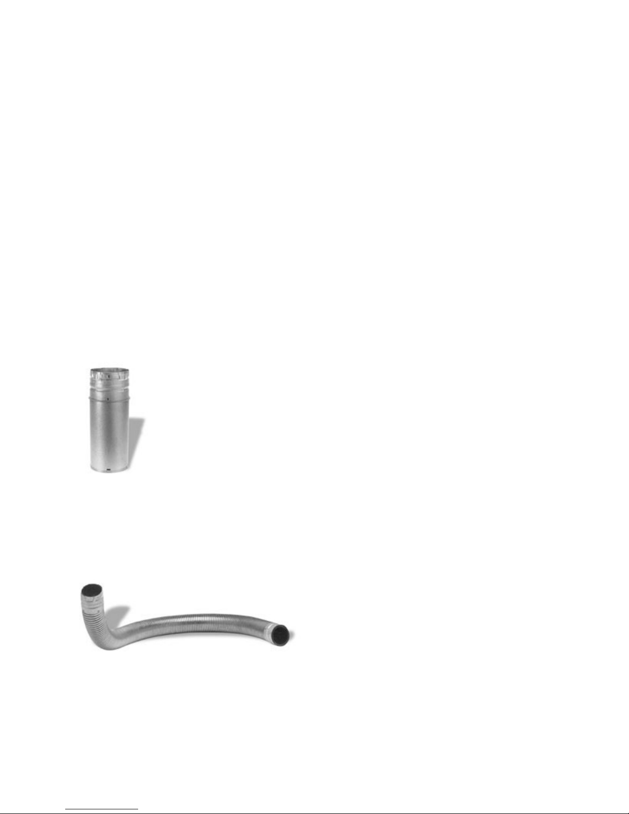
Examples of venting system components follow:
High temperature ceramic roping reduces potential fly ash escaping through joints.
Stainless steel inner liners resist corrosive flue gas damage to the system.
Flex pipe should be stainless steel, 4 ply construction with a total thickness of approximately .07
inches.
Element-MF Stove
10
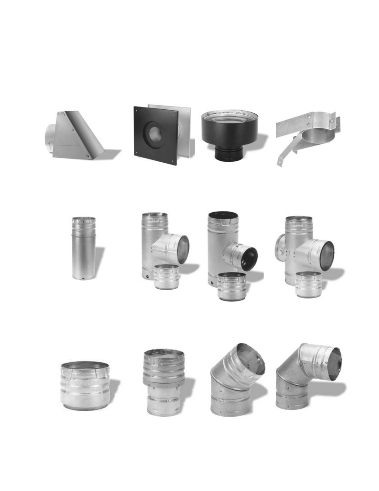
TYPICAL PL VENT COMPONENTS
RAIN CAP
VERTICAL OR WALL THIMBLE CHIMNEY SUPPORT BRACKET
HORIZONTAL ADAPTER
ADJUSTABLE LENGTH SINGLE TEE SINGLE REDUCTION DOUBLE TEE
PIPE w/TEE CAP TEE w/TEE CAP w/TEE CAP
PIPE ADAPTER INCREASER 450 ELBOW 900 ELBOW
Element-MF Stove
11

VENTING: DETERMINING MATERIALS
TYPE OF MATERIALS:
1. PL Vent / Corn Vent must be used.
2. All Joints in the venting installation must be fastened together using three screws. All joints of
the venting system must be sealed with High Temp Silicone to make a gas tight fit.
3. Exception: Single wall stainless steel may be used inside an existing chimney. (No
clearances to combustibles are needed on single wall stainless steel adaptors, rigid or flex pipe
installed within a chimney.)
4. A clean-out “tee” (PL Vent or “Quick-Connect Exhaust”) must be installed directly to the
Stove and at the bottom of each vertical run of the exhaust system. These tees are to assist in
periodically cleaning the pipe. Single or double clean-out tees may be used. The exhaust system
must be installed so the entire system can be cleaned without disassembly.
NOTE: ADHERE TO THE PL VENT CLEARANCES TO COMBUSTIBLES AS REQUIRED.
STRICTLY OBSERVE THE PL VENT MANUFACTURER’S SAFETY SPECIFICATIONS.
QUANTITY OF MATERIALS:
1. It is recommended that the vent system be installed with a minimum of three feet (3’) of
vertical rise above the exhaust port on the back of the Element-MF.
FAILURE TO PROVIDE THE NATURAL DRAFT THAT RESULTS FROM A VERTICAL
RISE MAY RESULT IN SMOKE BEING RELEASED INTO THE HOUSE WHEN
ELECTRICITY TO THE UNIT IS INTERRUPTED WHILE BURNING OR SMOLDERING
FUEL REMAINS IN THE BURN GRATE. (See “Battery Backup” on page 9)
2. It is not recommended to run vertical venting outside the heated environment where the
Element-MF is installed. Running a venting system in a cold environment may cause the flue
temperatures to cool down too much for adequate drafting.
Additional vertical exhaust venting should be provided when using:
a. More than one (1) elbow or tee; and/or
b. Horizontal runs of over three (3) feet. (Horizontal runs over 10 feet not recommended)
3. For a venting system ending in a horizontal run, the exhaust pipe must be terminated by a
listed end cap or a PL vent elbow (45 or 90 degrees). Note: End caps or elbows must vent
exhaust gases away from the building.
4. For termination above the building roofline a rain cap is required.
5. The exhaust pipe on all Element-MF’s is 3” O.D. to accommodate a pipe adaptor.
Element-MF Stove
12
VENTING: TERMINATION REQUIREMENTS
In determining optimum vent termination, carefully evaluate external conditions especially when
venting directly through a wall. Since you must deal with odors, gases, and fly ash, consider
aesthetics, prevailing winds, distances from air inlets and combustibles, location of adjacent
structures and any code requirements.
1. Exhaust must terminate above combustion air inlet elevation.
2. Do not terminate vent in any enclosed or semi-enclosed area, (i.e. Carports, garage, attic
crawl space, etc.) or any location that can build up a concentration of fumes.
3. Vent surfaces can get hot enough to cause burns if touched by children. Non-combustible
shielding or guards may be required
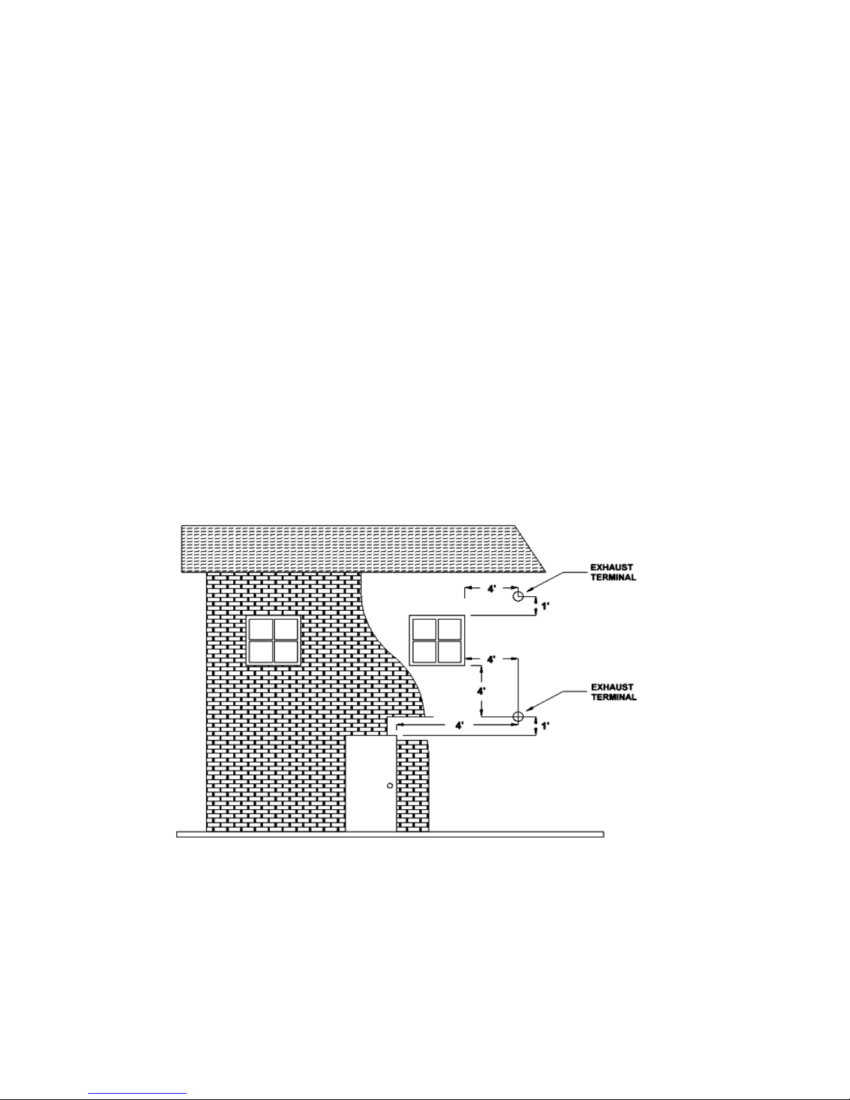
The type of installation must first be considered before determining the exact location of
the venting termination in relation ship to doors, window, cavities or air vents.
a. Without Outside Air connected to the unit. For this types of installation please refer to
the dimensions listed below in figure 4.
Figure 4
4’ (1.2 m) BELOW a door, window, cavity, or air vent
Or
4’ (1.2 m) HORIZONTALLY FROM a door, window, cavity, or air vent
Or
1’ (305 mm) ABOVE a door, window, cavity, or air vent
Element-MF Stove
13

b. With Outside Air Connected to the unit. In this manner the appliance is a Direct Vent
Appliance (sealed Combustion System) as listed in NFPA 211-6.
3.3.3.2 Direct Vent Appliance (Sealed Combustion System Appliance) A system
consisting of an appliance, combustion air and flue gas connections between the
appliance and the outside atmosphere, and a vent cap supplied by the manufacturer, and
constructed so that all the air for combustion is obtained from the outside atmosphere
and all flue gases are discharged to the outside atmosphere.
Special Venting Arrangements are listed in NFPA 211-31
10.7.1.2 The Vent Terminal of a Direct Vent Appliance with an input of 10000 BTU/Hr or
less shall be located at least 6” from any opening into a building, and such an appliance
with an input of over 10000 BTU/Hr, but not over 50000 BTU/Hr shall not be located
less than 9” from any opening through which vent gases could enter a building, and the
vent terminal of such appliance with an input over 50000 BTU/Hr shall be located not
less than 12” from the opening.
Figure 5
9” (229 mm) ABOVE, BELOW OR HORIZONTALLY FROM a door, window, cavity, or air
vent.
Element-MF Stove
14
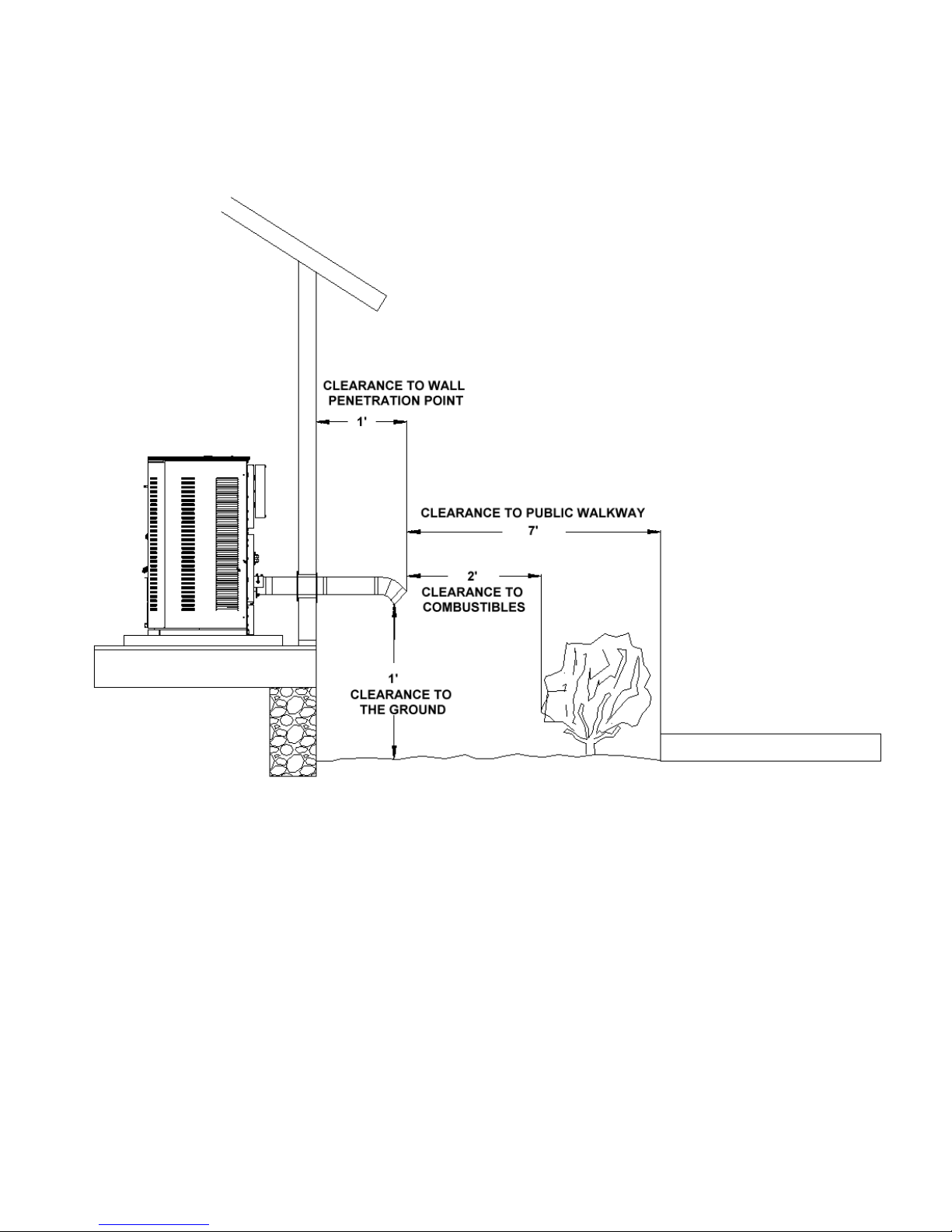
VENTING: TERMINATION CLEARANCE REQUIREMENTS
Figure 6
THE EXHAUST TERMINATION LOCATION MUST BE AT LEAST
1’ (305 mm) ABOVE the ground level
7’ (2.1 m) FROM a public walkway
1’ (305 mm) FROM The wall penetration point
3’ (915mm) FROM a gas meter/regulator assembly
2’ (610 mm) FROM any adjacent combustibles such as:
Adjacent buildings, fences, protruding parts
of the structure, roof eaves or overhangs,
plants, shrubs, etc.
Element-MF Stove
15
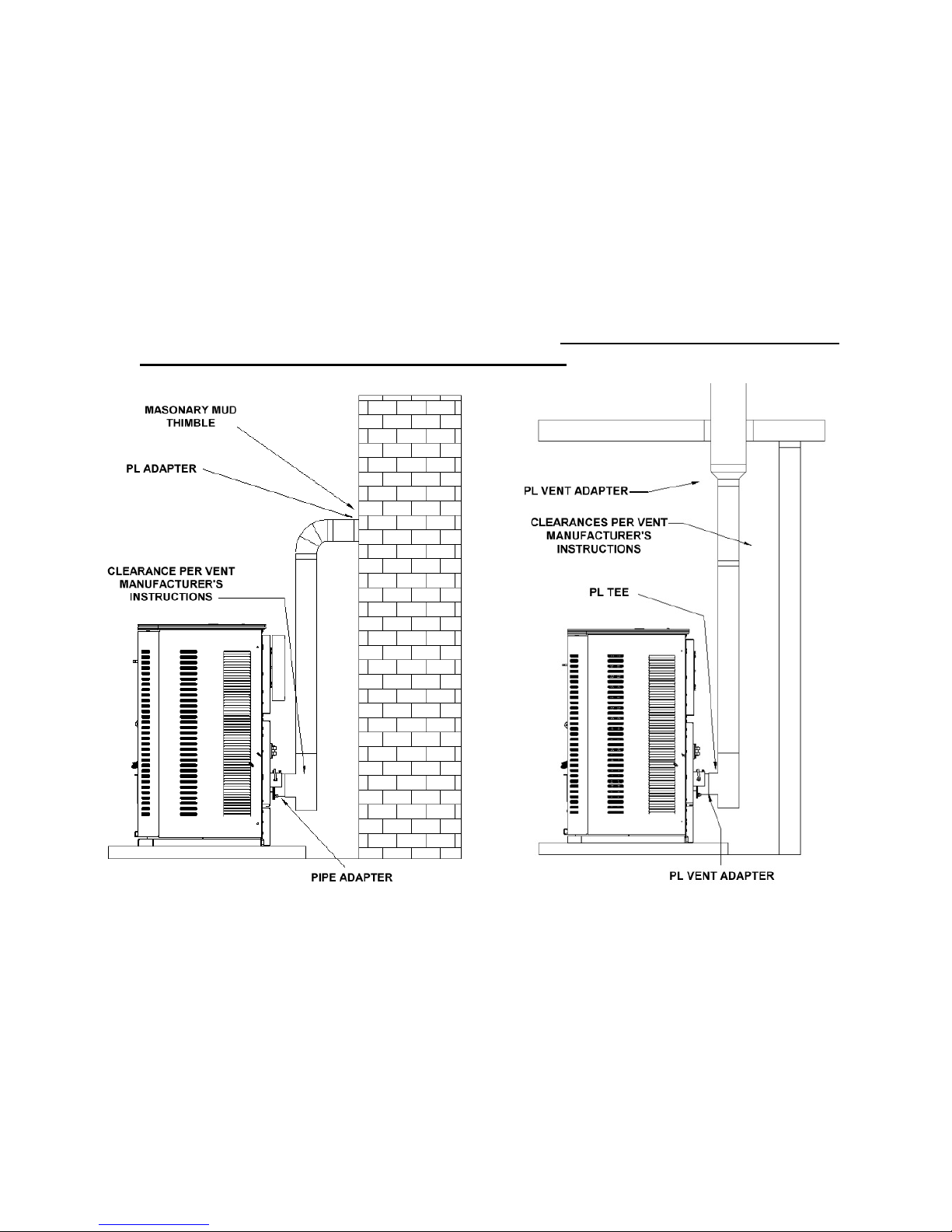
VENTING: INTO AN EXISTING CHIMNEY
The stove may be connected to an existing Class A chimney or a masonry chimney which meets
the minimum requirements of NFPA 211.
1. If the stove’s exhaust is connected to a masonry chimney, the masonry chimney must be free
of cracks that could leak exhaust gases or fly ash. A relining of the chimney with either PL
vent or single wall stainless steel pipe may be necessary to bring the chimney into
compliance.
2. When chimneys are relined, a chimney chase cap that reduces the outlet of the chimney to
the size of the liner is required. Extend the exhaust vent above the chimney chase cap and
finish it off with a rain cap. A single wall liner may need to be insulated to maintain
adequate exhaust temperatures in the vent system Note: Outside Chimneys frequently
are difficult to keep warm, if in doubt insulate the liner.
Figure 7 Figure 8
Venting into Masonry Chimney Venting into a Class A Chimney
3. Venting into the side of an existing masonry chimney must be done through a masonry
thimble. When wall penetration is necessary to access a masonry chimney, use a listed PL
vent wall thimble. (Figure 7).
4. When venting into a Class A steel chimney, use an appropriate PL Vent adapter. (Figure 8)
Element-MF Stove
16
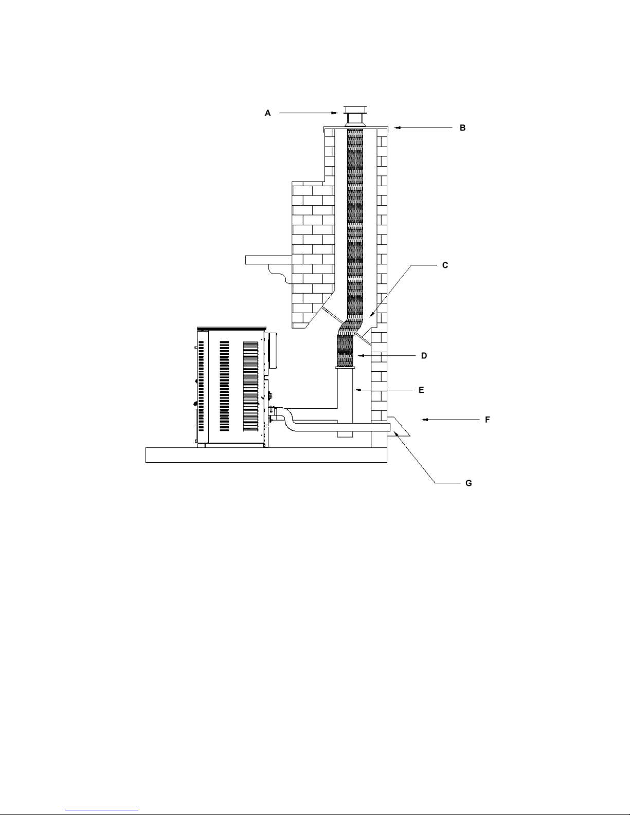
Hearth Mount
A – Vertical Cap
B – Chimney Flashing
C – Positive Block Off Plate
D – Stainless Steel Liner / PL Vent System
E – PL Tee or Single Wall Tee
F – Outside Air Shield – May be needed
G – 2” Metal Outside Air Pipe - Optional
Venting to the Top of Chimney
When installing as a hearth mount stove into a fireplace, the unit must either be relined terminating
above the chimney chase top, or positively connected to the existing chimney system using a block off
plate (C). An approved flex liner or PL vent must be used. A chimney system with known drafting
problems may require a liner, which may also need to be insulated to keep vent system warm in
a cold chimney environment.
Legend
Figure 9
Element-MF Stove
17
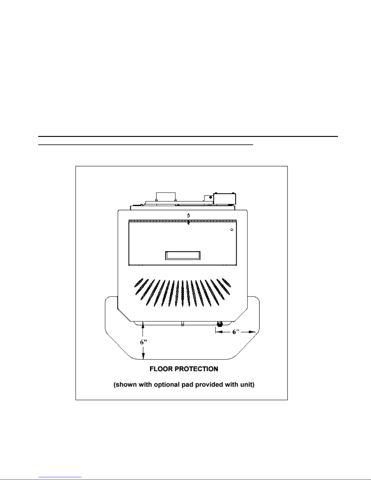
FLOOR PROTECTION
The stove must be installed on a Non-Combustible Surface.
Hearth models may be placed directly on the noncombustible hearth of a fireplace.
The Hearth / Non-Combustible pad must extend a minimum of 6” (152 mm) in Front of Unit and
beyond each side of the Fuel Loading and Ash Removal Opening(s).
Optional Spark Arrestor Pad provided with unit may only be used on a Solid Surface Floor, such as
Wood Flooring, Laminate Flooring or Linoleum. Do not use on Carpet.
Figure 10
Floor protection
(Top View)
Element-MF Stove
18
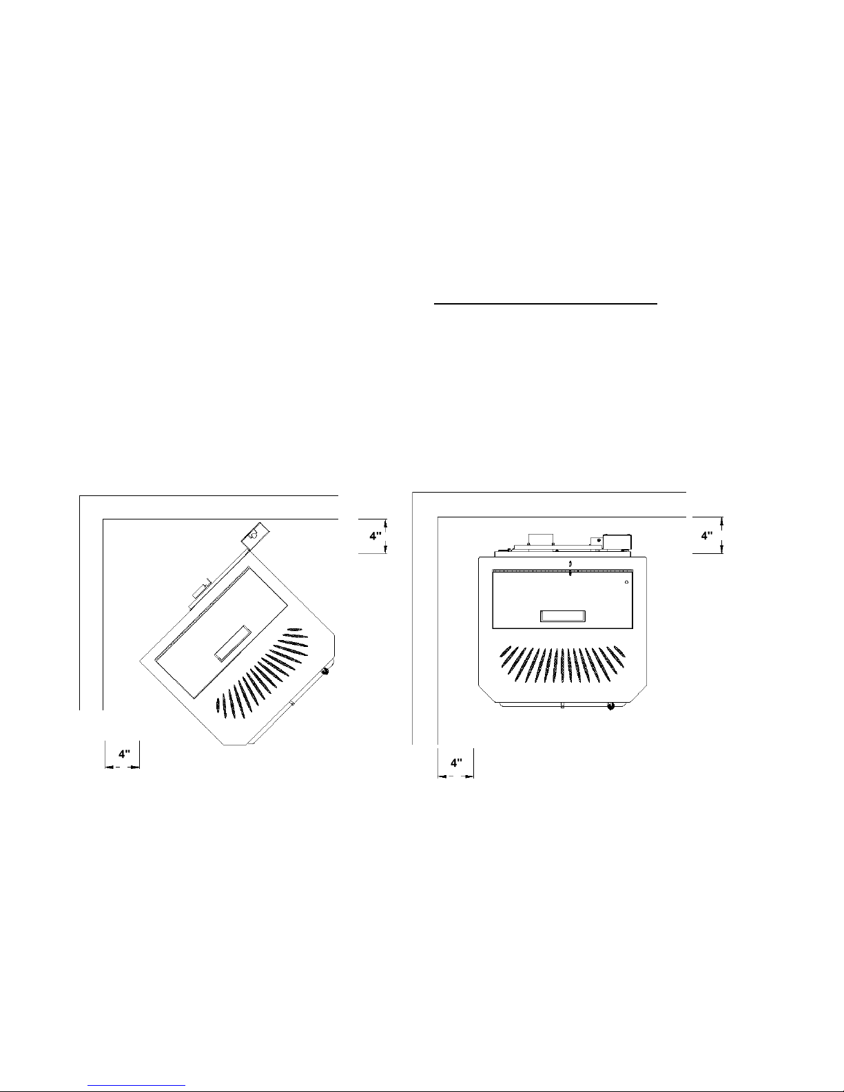
MINIMUM CLEARANCES (INCHES) TO COMBUSTIBLE MATERIAL
Figure(s): From:
12, 15 Sides of stove 4”
12, 15 Back of stove 4”
11 Corner of stove 4”
7, 8 Vent pipe Per Manufacturer’s Instructions
13 Stove to mantel 12”
10 Floor protection: Front (from faceplate) 6”
10 Floor protection: Sides & back of stove 0”
14 Alcove: Vertical to Combustibles 16”
15 Alcove: Sides 4”
15 Alcove: Back 4”
Figure 11 (Top View) Figure 12 (Top View)
Clearances: corners of stove Clearances Sides and Back
Element-MF Stove
19
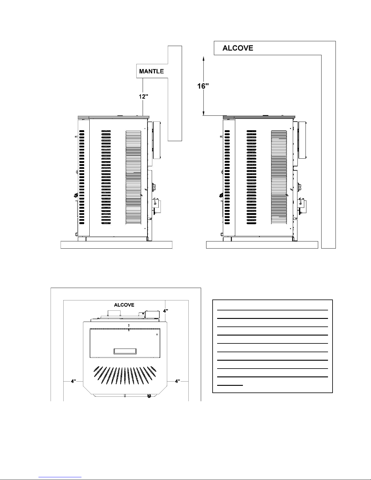
Floor Pad and Mantle Clearances Alcove Installation (Side View)
Figure 13 Figure 14
Although 4“ is the minimum
clearance to the sides of the stove,
this is not recommended due to the
need for access into the inside of the
stove for the maintenance, as spelled
out in the Operations Manual.
Please read the section covering
Daily, Periodic and Yearly
Maintenance in the Operations
Manual.
Figure 15
Alcove Installation (Top View)
Element-MF Stove
20
 Loading...