

Page 1

STC MCU Limited.
Mobile:(86)13922809991 Tel:86-755-82948412 Fax:86-755-82905966
STC MCU Limited.
website:www.STCMCU.com
1
www.STCMCU.com
STC12C2052AD series MCU
STC12LE2052AD series MCU
Data Sheet
STC MCU Limited
www.STCMCU.com
Update date: 2011-7-15
Page 2

STC MCU Limited
CONTENTS
Chapter 1. Introduction ................................................................7
1.1 Features ................................................................................................. 7
1.2 Block diagram ....................................................................................... 8
1.3 Pin Configurations ................................................................................ 9
1.4 STC12C2052AD series Selection Table.............................................. 10
1.5 STC12C2052AD series Minimum Application System .......................11
1.6 STC12C2052AD series MCU Typical Application Circuit for ISP .... 12
1.7 Pin Descriptions .................................................................................. 14
1.8 Package Dimension Drawings ............................................................. 16
1.9 STC12C2052AD series MCU naming rules ....................................... 18
1.10 Global Unique Identification Number (ID) ....................................... 19
Chapter 2. Clock, Power Management and Reset ...................22
2.1 Clock ................................................................................................... 22
2.1.1 On-Chip R/C Clock and External Crystal/Clcok are Optional in STC-ISP.exe 22
2.1.2 Divider for System Clock .................................................................................. 23
2.1.3 How to Know Internal RC Oscillator frequency(Internal clock frequency) .....24
2.1.4 Programmable Clock Output .............................................................................. 27
2.1.4.1 Timer 0 Programmable Clock-out on P1.0 ....................................................................... 28
2.1.4.2 Timer 1 Programmable Clock-out on P1.1 ....................................................................... 29
2.2 Power Management Modes ................................................................. 30
2.2.1 Slow Down Mode ............................................................................................... 31
2.2.2 Idle Mode ............................................................................................................ 32
2.2.3 Stop / Power Down (PD) Mode and Demo Program (C and ASM) ................... 33
2.3 RESET Sources ................................................................................... 39
2.3.1 RESET Pin .......................................................................................................... 39
2.3.2 Software RESET ................................................................................................. 39
2.3.3 Power-On Reset (POR) ....................................................................................... 40
2.3.4 MAX810 power-on-Reset delay ......................................................................... 40
2.3.5 Internal Low Voltage Detection Reset ................................................................ 41
2.3.6 Watch-Dog-Timer ............................................................................................... 44
2.3.7 Warm Boot and Cold Boot Reset ........................................................................ 48
Page 3

STC MCU Limited
Chapter 3. Memory Organization .............................................49
3.1 Program Memory ................................................................................ 49
3.2 Data Memory(SRAM) ......................................................................... 50
3.3 Special Function Registers .................................................................. 53
3.3.1 Special Function Registers Address Map ........................................................... 53
3.3.2 Special Function Registers Bits Description ...................................................... 54
Chapter 4. Configurable I/O Ports of STC12C2052AD series 58
4.1 I/O Ports Configurations ..................................................................... 58
4.2 I/O ports Modes ................................................................................... 60
4.2.1 Quasi-bidirectional I/O ....................................................................................... 60
4.2.2 Push-pull Output ................................................................................................. 61
4.2.3 Input-only (High-Impedance) Mode................................................................... 61
4.2.4 Open-drain Output .............................................................................................. 61
4.3 I/O port application notes .................................................................... 62
4.4 Typical transistor control circuit .......................................................... 62
4.5 Typical diode control circuit ................................................................ 62
4.6 3V/5V hybrid system ........................................................................... 63
4.7 How to make I/O port low after MCU reset ........................................ 64
4.8 I/O status while PWM outputing ......................................................... 64
4.9 I/O drive LED application circuit ........................................................ 65
4.10 I/O immediately drive LCD application circuit................................. 66
4.11 Using A/D Conversion to scan key application circuit ...................... 67
Chapter 5. Instruction System ...................................................68
5.1 Addressing Modes ............................................................................... 68
5.2 Instruction Set Summary ..................................................................... 69
5.3 Instruction Definitions ......................................................................... 74
Chapter 6. Interrupt System .................................................... 111
6.1 Interrupt Structure ..............................................................................113
6.2 Interrupt Register ................................................................................115
6.3 Interrupt Priorities ............................................................................. 125
6.4 How Interrupts Are Handled ............................................................. 126
6.5 External Interrupts ............................................................................ 127
6.6 Response Time ................................................................................. 131
Page 4

STC MCU Limited
6.7 Demo Programs about Interrupts (C and ASM) ................................ 132
6.7.1 External Interrupt 0 (
INT0
) Demo Programs (C and ASM) ........................... 132
6.7.2 External Interrupt 1 (
INT1
) Demo Programs (C and ASM) ........................... 136
6.7.3 Programs of P3.4/T0 Interrupt(falling edge) used to wake up PD mode .........140
6.7.4 Programs of P3.5/T1 Interrupt(falling edge) used to wake up PD mode .........142
6.7.5 Program of P3.0/RxD Interrupt(falling edge) used to wake up PD mode ........ 144
6.7.6 Program of PCA Interrupt used to wake up Power Down mode ...................... 147
Chapter 7. Timer/Counter 0/1 .................................................151
7.1 Special Function Registers about Timer/Counter .............................. 151
7.2 Timer/Counter 0
Mode of Operation (Compatible with traditional 8051 MCU) ........155
7.2.1
Mode 0 (13-bit Timer/Counter) ..................................................................................... 155
7.2.2
Mode 1 (16-bit Timer/Counter) and Demo Programs (C and ASM) ............................. 156
7.2.3
Mode 2 (8-bit Auto-Reload Mode) and Demo Programs (C and ASM) ........................160
7.2.4
Mode 3 (Two 8-bit Timers/Couters) .............................................................................. 163
7.3 Timer/Counter 1 Mode of Operation ................................................. 164
7.3.1
Mode 0 (13-bit Timer/Counter) ..................................................................................... 164
7.3.2
Mode 1 (16-bit Timer/Counter) and Demo Programs (C and ASM) ............................. 165
7.3.3
Mode 2 (8-bit Auto-Reload Mode) and Demo Programs (C and ASM) ........................169
7.4 Programmable Clock Output and Demo Programs (C and ASM) .... 172
7.4.1 Timer 0 Programmable Clock-out on P1.0 and Demo Program(C and ASM) . 174
7.4.2 Timer 1 Programmable Clock-out on P1.1 and Demo Program(C and ASM) . 177
7.5 Application note for Timer in practice .............................................. 180
Chapter 8. UART with Enhanced Function ...........................181
8.1 Special Function Registers about UART ........................................... 181
8.2 UART Operation Modes ................................................................... 185
8.2.1 Mode 0: 8-Bit Shift Register............................................................................. 185
8.2.2 Mode 1: 8-Bit UART with Variable Baud Rate ................................................ 187
8.2.3 Mode 2: 9-Bit UART with Fixed Baud Rate .................................................... 189
8.2.4 Mode 3: 9-Bit UART with Variable Baud Rate ................................................ 191
8.3 Frame Error Detection ....................................................................... 193
8.4 Multiprocessor Communications ...................................................... 193
8.5 Automatic Address Recognition ........................................................ 194
8.6 Buad Rates ......................................................................................... 196
8.7 Demo Programs about UART (C and ASM) ..................................... 197
Page 5

STC MCU Limited
Chapter 9. Analog to Digital Converter ..................................203
9.1 A/D Converter Structure .................................................................... 203
9.2 Registers for ADC ............................................................................. 205
9.3 Application Circuit of A/D Converter .............................................. 208
9.4 ADC Application Circuit for Key Scan ............................................. 209
9.5 A/D reference voltage source ............................................................ 210
9.6 Program using interrupts to demostrate A/D Conversion .................211
9.7 Program using polling to demostrate A/D Conversion .................... 217
Chapter 10. Programmable Counter Array(PCA) ................223
10.1 SFRs related with PCA .................................................................... 223
10.2 PCA/PWM Structure ....................................................................... 228
10.3 PCA Modules Operation Mode ...................................................... 230
10.3.1 PCA Capture Mode ......................................................................................... 230
10.3.2 16-bit Software Timer Mode .......................................................................... 231
10.3.3 High Speed Output Mode ............................................................................... 232
10.3.4 Pulse Width Modulator Mode (PWM mode)..................................................233
10.4 Programs for PCA module extended external interrupt ................. 234
10.5 Demo Programs for PCA module acted as 16-bit Timer ................ 238
10.6 Programs for PCA module as 16-bit High Speed Output ................ 242
10.7 Demo Programs for PCA module as PWM Output ........................ 246
10.8 Demo Program for PCA clock base on Timer 1 overflow rate....... 250
10.9 Using PWM achieve D/A Conversion function reference circuit ... 254
Chapter 11. Serial Peripheral Interface (SPI) ........................255
11.1 Special Function Registers related with SPI .................................... 255
11.2 SPI Structure .................................................................................... 258
11.3 SPI Data Communication ................................................................ 259
11.3.1 SPI Configuration ........................................................................................... 259
11.3.2 SPI Data Communication Modes ................................................................... 260
11.3.3 SPI Data Modes .............................................................................................. 262
11.4 SPI Function Demo Programs (Single Master — Single Slave) ..... 264
11.4.1 SPI Function Demo Programs using Interrupts (C and ASM) ........................ 264
11.4.2 SPI Function Demo Programs using Polling (C and ASM) ............................ 270
Page 6

11.5 SPI Function Demo Programs (Each other as the Master-Slave) .... 276
11.5.1 SPI Function Demo Programs using Interrupts (C and ASM) ........................ 276
11.5.2 SPI Function Demo Programs using Polling .................................................. 282
Chapter 12. IAP / EEPROM ....................................................288
12.1 IAP / EEPROM Special Function Registers.................................... 289
12.2 STC12C2052AD series Internal EEPROM Allocation Table ......... 292
12.3 IAP/EEPROM Assembly Language Program Introduction ............ 293
12.4 EEPROM Demo Program (C and ASM) ......................................... 296
Chapter 13. STC12 series Development/Programming Tool 304
13.1 In-System-Programming (ISP) principle ......................................... 304
13.2 STC12C2052AD series Typical Application Circuit for ISP .......... 305
13.3 PC side application usage ................................................................ 307
13.4 Compiler / Assembler Programmer and Emulator .......................... 309
13.5 Self-Defined ISP download Demo ................................................. 309
Appendix A: Assembly Language Programming ...................313
Appendix B: 8051 C Programming .........................................335
Appendix C:
STC12C2052AD series Electrical Characteristics
..............................................................................345
Appendix D: Program for indirect addressing inner 256B RAM
..............................................................................347
Appendix E: Using Serial port expand I/O interface ............348
Appendix F:
Use STC MCU common I/O driving LCD Display
..............................................................................350
Appendix G: LED driven by an I/O port and Key Scan ........357
Appendix H: How to reduce the Length of Code through Keil C
..............................................................................358
Appendix I: Notes of STC12C2052AD series Application ....359
Appendix J: Notes of STC12 series Replaced Traditional 8051 .
..............................................................................360
Page 7

STC MCU Limited.
Mobile:(86)13922809991 Tel:86-755-82948412 Fax:86-755-82905966
STC MCU Limited.
website:www.STCMCU.com
7
www.STCMCU.com
1.1 Features
Enhanced 8051 Central Processing Unit ,1T per machine cycle, faster 8~12 times than the rate of a standard
8051.
Operating voltage range: 5.5V ~ 3.5V or 2.2V ~ 3.6V (STC12LE2052AD).
Operating frequency range: 0- 35MHz, is equivalent to standard 8051:0~420MHz
On-chip 1K/2K/3K/4K/5K... FLASH program memory with flexible ISP/IAP capability
On-chip 256 byte RAM
Power control: idle mode(can be waked up by any interrupt) and power-down mode(can be waked up by
external interrupts).
Code protection for flash memory access
Excellent noise immunity, very low power consumption
Four 16-bit timer/counter, be compatible with Timer0/Timer1 of standard 8051, 2-channel PCA can be
available as two timers.
9 vector-address, 4 level priority interrupt capability
One enhanced UART with hardware address-recognition and frame-error detection function
One 15 bits Watch-Dog-Timer with 8-bit pre-scaler (one-time-enabled)
SPI Master/Slave communication interface
Two channel Programmable Counter Array (PCA)
8-bit, 8-channel high-speed Analog-to-Digital Converter (ADC), up to 100 thousands times per second
Simple internal RC oscillator and external crystal clock
Three power management modes: idle mode, slow down mode and power-down mode
Power down mode can be woken-up by P3.2/INT0, P3.3/INT1, P3.4/T0, P3.5/T1, P3.0/RxD, P3.7/PCA0, and
P3.5/PCA1
Operation Temperature: -40 ~ + 85℃ (industrial) / 0 ~ 75℃ (Commercial)
15 common programmable I/O ports are available
Programmable clock output Function. T0 output the clock on P1.0, T1 output the clock on P1.1.
Five package type : SOP-20, DIP-20, LSSOP-20.
•
•
•
•
•
•
•
•
•
•
•
•
•
•
•
•
•
•
•
•
•
•
Chapter 1. Introduction
STC12C2052AD is a single-chip microcontroller based on a high performance 1T architecture 8051 CPU, which
is produced by STC MCU Limited. With the enhanced kernel, STC12C2052AD executes instructions in 1~6
clock cycles (about 8~12 times the rate of a standard 8051 device), and has a fully compatible instruction set with
industrial-standard 8051 series microcontroller. In-System-Programming (ISP) and In-Application-Programming
(IAP) support the users to upgrade the program and data in system. ISP allows the user to download new code
without removing the microcontroller from the actual end product; IAP means that the device can write nonvalatile data in Flash memory while the application program is running. The STC12C2052AD retains all features
of the standard 80C51. In addition, the STC12C2052AD has a 9-sources, 4-priority-level interrupt structure, 8-bit
ADC (100 thousands times per second), on-chip crystal oscillator, MAX810 special reset circuit, 2-channel PCA
and PWM, SPI, a one-time enabled Watchdog Timer and so on.
Page 8

STC MCU Limited.
Mobile:(86)13922809991 Tel:086-755-82948412
Fax:86-755-82905966
STC MCU Limited. website:www.STCMCU.com
8
www.STCMCU.com
1.2 Block diagram
The CPU kernel of STC12C2052AD is fully compatible to the standard 8051 microcontroller, maintains all
instruction mnemonics and binary compatibility. With some great architecture enhancements, STC12C2052AD
executes the fastest instructions per clock cycle. Improvement of individual programs depends on the actual
instructions used.
STC12C2052AD Block Diagram
RAM
256B
FLASH
Program
Counter
PCA
(2-channel)
SPI
B Register
ACC
TMP2
TMP1
Stack
Pointer
ALU
PSW
WDT
Control
Unit
XTAL2XTAL1
RESET
ISP/IAP
Address
Generator
Timer 0/1
Enhanced
UART
LVD/LVR
Port 3
Latch
Port 3
Driver
P3
Port1 Latch
Port 1 Driver
P1.0 ~ P1.7
ADC
P1.0 ~ P1.7
8
Page 9

STC MCU Limited.
Mobile:(86)13922809991 Tel:86-755-82948412 Fax:86-755-82905966
STC MCU Limited.
website:www.STCMCU.com
9
www.STCMCU.com
1.3 Pin Configurations
All packages meet the European Union RoHS standards. LQFP-32 also conform to the Green standard.
Packages such as SOP-20 are strongly recommended though the traditional DIP packages are steady supplied.
20
19
18
17
16
15
14
13
12
11
1
2
3
4
5
6
7
8
9
10
VCC
P1.3/ADC3
RST
TxD/P3.1
XTAL2
XTAL1
Gnd
INT1/P3.3
INT0/P3.2
SOP-20 / DIP-20
P1.7/SCLK/ADC7
P1.6/MISO/ADC6
P1.5/MOSI/ADC5
P1.2/ADC2
P1.1/ADC1/CLKOUT1
P1.0/ADC0/CLKOUT0
P3.7/PCA0/PWM0
RxD/P3.0
ECI/T0/P3.4
PWM1/PCA1/T1/P3.5
20
19
18
17
16
15
14
13
12
11
1
2
3
4
5
6
7
8
9
10
VCC
P1.3
RST
TxD/P3.1
XTAL2
XTAL1
Gnd
INT1/P3.3
INT0/P3.2
SOP-20 / DIP-20
P1.7/SCLK
P1.6/MISO
P1.5/MOSI
P1.2
P1.1/CLKOUT1
P1.0/CLKOUT0
P3.7/PCA0/PWM0
RxD/P3.0
ECI/T0/P3.4
PWM/PCA1/T1/P3.5
P1.4/SS
P1.4/SS/ADC4
TSSOP-20
TSSOP-20
Super small package : TSSOP-20, 6.4mm×6.4mm
STC12C2052AD series (with A/D Converter),20-Pin
15 I/O ports
STC12C2052 series (without A/D Converter),20-Pin
Page 10

STC MCU Limited.
Mobile:(86)13922809991 Tel:086-755-82948412 Fax:86-755-82905966
STC MCU Limited. website:www.STCMCU.com
10
www.STCMCU.com
1.4 STC12C2052AD series Selection Table
Type
1T 8051
MCU
Operation
Voltage
(V)
Flash
(Byte)
SRAM
(Byte)
Timer
T0&T1
PCA
Timer
Programmable
Clock Output
U
A
R
T
EEP
ROM
16-bit
PCA/
8-bit
PWM
D/A
A/D
8-ch
W
D
T
Built-in
Reset
SPI
Package of 20-Pin
(15 I/O ports)
STC12C2052AD
series Selection Table
STC12C1052 5.5-3.5 1K 256 Y 2 Y Y Y 2-ch Y Y Y SOP/LSSOP/DIP
STC12C1052AD 5.5-3.5 1K 256 Y 2 Y Y Y 2-ch 8-bit Y Y Y SOP/LSSOP/DIP
STC12C2052 5.5-3.5 2K 256 Y 2 Y Y Y 2-ch Y Y Y SOP/LSSOP/DIP
STC12C2052AD 5.5-3.5 2K 256 Y 2 Y Y Y 2-ch 8-bit Y Y Y SOP/LSSOP/DIP
STC12C3052 5.5-3.5 3K 256 Y 2 Y Y IAP 2-ch Y Y Y SOP/LSSOP/DIP
STC12C3052AD 5.5-3.5 3K 256 Y 2 Y Y Y 2-ch 8-bit Y Y Y SOP/LSSOP/DIP
STC12C4052 5.5-3.5 4K 256 Y 2 Y Y Y 2-ch Y Y Y SOP/LSSOP/DIP
STC12C4052AD 5.5-3.5 4K 256 Y 2 Y Y Y 2-ch 8-bit Y Y Y SOP/LSSOP/DIP
STC12C5052 5.5-3.5 5K 256 Y 2 Y Y Y 2-ch Y Y Y Application program
can be modified in
application program
area (AP area)
STC12C5052AD 5.5-3.5 6K 256 Y 2 Y Y Y 2-ch 8-bit Y Y Y
STC12LE2052AD
series Selection Table
STC12LE1052 3.6-2.2 1K 256 Y 2 Y Y Y 2-ch Y Y Y SOP/LSSOP/DIP
STC12LE1052AD 3.6-2.2 1K 256 Y 2 Y Y Y 2-ch 8-bit Y Y Y SOP/LSSOP/DIP
STC12LE2052 3.6-2.2 2K 256 Y 2 Y Y Y 2-ch Y Y Y SOP/LSSOP/DIP
STC12LE2052AD 3.6-2.2 2K 256 Y 2 Y Y Y 2-ch 8-bit Y Y Y SOP/LSSOP/DIP
STC12LE3052 3.6-2.2 3K 256 Y 2 Y Y Y 2-ch Y Y Y SOP/LSSOP/DIP
STC12LE3052AD 3.6-2.2 3K 256 Y 2 Y Y Y 2-ch 8-bit Y Y Y SOP/LSSOP/DIP
STC12LE4052 3.6-2.2 4K 256 Y 2 Y Y Y 2-ch Y Y Y SOP/LSSOP/DIP
STC12LE4052AD 3.6-2.2 4K 256 Y 2 Y Y Y 2-ch 8-bit Y Y Y SOP/LSSOP/DIP
STC12LE5052 3.6-2.2 5K 256 Y 2 Y Y Y 2-ch Y Y Y Application program
can be modified in
application program
area (AP area)
STC12LE5052AD 3.6-2.2 5K 256 Y 2 Y Y Y 2-ch 8-bit Y Y Y
Page 11

STC MCU Limited.
Mobile:(86)13922809991 Tel:86-755-82948412 Fax:86-755-82905966
STC MCU Limited.
website:www.STCMCU.com
11
www.STCMCU.com
1.5 STC12C2052AD series Minimum Application System
When the frequency of crystal oscillator is lower than 12MHz,
it is suggested not to use C1 and R1 replaced by 1K
resistor connect to ground.
But R/C reset circuit is also suggest to reserve.
About crystals circuit:
If using internal R/C oscillator clock (4MHz ~ 8MHz, manufacturing error), XTAL1 and XTAL2 pin should
be floated.
If External clock frequency is higher than 33MHz, it is recommended to directly use external active crystals
which clock are input from XTAL1 pin and XTAL2 pin must be floated.
System power/5V/3V
Vin
SW1
Power On
C6
C5
C2<33pF
C3<33pF
X1
10K
C1
+
+
1
2
3
4
5
6
7
8
9
10
20
19
18
17
16
15
14
13
12
11
RST
P3.0/RxD
P3.1/TxD
XTAL2
XTAL1
P3.2/INT0
P3.3/INT1
P3.4/T0/ECI
P3.5/T1/PCA1/PWM1
Gnd
VCC
ADC7/SCLK/P1.7
ADC6/MISO/P1.6
ADC5/MOSI/P1.5
ADC4/SS/P1.4
ADC3/P1.3
ADC2/P1.2
CLKOUT1/ADC1/P1.1
CLKOUT0/ADC0/P1.0
PWM0/PCA0/P3.7
Page 12

STC MCU Limited.
Mobile:(86)13922809991 Tel:086-755-82948412 Fax:86-755-82905966
STC MCU Limited. website:www.STCMCU.com
12
www.STCMCU.com
1.6 STC12C2052AD series MCU Typical Application Circuit for ISP
—— MCU should be connected to computer through RS-232 converter to download program
1
2
3
4
5
6
7
8
16
15
14
13
12
11
10
9
Vcc
Gnd
T1OUT
R1IN
R1OUT
T1IN
T2IN
R2OUT
C1+
V+
C1-
C2+
C2-
V-
T2OUT
R2IN
Reset
U1-P1.0
U1-P1.1
MCU-VCC
U1-P3.0
U1-P3.1
GND
USB+5V T1OUT R1IN
GND
USB1
Vcc
+
Vcc
Gnd
PC_RxD(COM Pin2)
PC_TxD(COM Pin3)
2
3
5
PC COM
MAX232,MAX3232,SP232,SP3232
Vcc
USB +5V
Vin
SW1
Power On
+
Download user procedure to STC MCU by
the software STC-ISP
programmer
This circuit has been made as a STC12C2052AD series
microcontroller ISP download programming tool
1K
<33pF
<33pF
1K
+
C1
Vcc
R1
10K
Users are suggested hold this
interface on the system , which
can be convenient to download
the users program online.
System Power
1
2
3
4
5
6
7
8
9
10
20
19
18
17
16
15
14
13
12
11
RST
P3.0/RxD
P3.1/TxD
XTAL2
XTAL1
P3.2/INT0
P3.3/INT1
P3.4/T0/ECI
P3.5/T1/PCA1/PWM1
Gnd
VCC
ADC7/SCLK/P1.7
ADC6/MISO/P1.6
ADC5/MOSI/P1.5
ADC4/SS/P1.4
ADC3/P1.3
ADC2/P1.2
CLKOUT1/ADC1/P1.1
CLKOUT0/ADC0/P1.0
PWM0/PCA0/P3.7
20 Pin
If using internal R/C oscillator clock
(4M Hz ~ 8MH z, manufacturing err or) ,
XTAL1 and XTAL2 pin should be floated.
If External clock frequency is higher
than 33MHz, it is recommended to directly
use external active c rystals which clock
are input from XTAL1 pin and XTAL2 pin
must be floated.
But R/C r eset circuit is
also suggest to reserve.
When the frequency of crystal oscillator is lower
than 12MHz, it is suggested not to use C1 and
R1 replaced by 1K resistor connect to ground.
Page 13

STC MCU Limited.
Mobile:(86)13922809991 Tel:86-755-82948412 Fax:86-755-82905966
STC MCU Limited.
website:www.STCMCU.com
13
www.STCMCU.com
Users in their target system, such as the P3.0/P3.1 through the RS-232 level shifter connected to the computer
after the conversion of ordinary RS-232 serial port to connect the system programming / upgrading client
software. If the user panel recommended no RS-232 level converter, should lead to a socket, with Gnd/P3.1/
P3.0/Vcc four signal lines, so that the user system can be programmed directly. Of course, if the six signal lines
can lead to Gnd/P3.1/P3.0/Vcc/P1.1/P1.0 as well, because you can download the program by P1.0/P1.1 ISP ban.
If you can Gnd/P3.1/P3.0/Vcc/P1.1/P1.0/Reset seven signal lines leads to better, so you can easily use "offline
download board (no computer)" .
ISP programming on the Theory and Application Guide to see "STC12C2052AD Series MCU Development /
Programming Tools Help"section. In addition, we have standardized programming download tool, the user can
then program into the goal in the above systems, you can borrow on top of it RS-232 level shifter connected to
the computer to download the program used to do. Programming a chip roughly be a few seconds, faster than the
ordinary universal programmer much faster, there is no need to buy expensive third-party programmer?.
PC STC-ISP software downloaded from the website www.STCMCU.com
Page 14

STC MCU Limited.
Mobile:(86)13922809991 Tel:086-755-82948412 Fax:86-755-82905966
STC MCU Limited. website:www.STCMCU.com
14
www.STCMCU.com
1.7 Pin Descriptions
MNEMONIC
Pin Number
Description
LQFP-32 SOP-32
SOP-28/
SKDIP-28
SOP-20/DIP-20/
TSSOP-20
P1.0/ADC0/CLKOUT0 16 20 18 12
P1.0 common I/O port PORT1[0]
ADC0
Analog to Digital Converter Input
channel 0
CLKOUT0
Programmable clock output of Timer/
couter 0
P1.1/ADC1/CLKOUT1 17 21 19 13
P1.1 common I/O port PORT1[1]
ADC1
Analog to Digital Converter Input
channel 1
CLKOUT1
rogrammable clock output of Timer/
counter 1
P1.2/ADC2 18 22 20 14
P1.2 common I/O port PORT1[2]
ADC2
Analog to Digital Converter Input
channel 2
P1.3/ADC3 20 24 21 15
P1.3 common I/O port PORT1[3]
ADC3
Analog to Digital Converter Input
channel 3
P1.4/ADC4/
SS
21 25 22 16
P1.4 common I/O port PORT1[4]
ADC4
Analog to Digital Converter Input
channel 4
SS
slave-select signal of serial peripheral
interface, which is active low.
P1.5/ADC5/MOSI 23 27 23 17
P1.5 common I/O port PORT1[5]
ADC5
Analog to Digital Converter Input
channel 5
MOSI
Master Out, Slave In signal
P1.6/ADC6/MISO 24 28 24 18
P1.6 common I/O port PORT1[6]
ADC5
Analog to Digital Converter Input
channel 6
MISO
Master In, Slave Out signal
P1.7/ADC7/SCLK 25 29 25 19
P1.7 common I/O port PORT1[7]
ADC7
Analog to Digital Converter Input
channel 7
SCLK
The clock signal of serial peripheral
interface
P3.0/RxD 32 4 4 2
P3.0 common I/O port PORT3[0]
RxD Serial recive port
P3.1/TxD 1 5 5 3
P3.1 common I/O port PORT3[1]
TxD Serial transmit port
Page 15

STC MCU Limited.
Mobile:(86)13922809991 Tel:86-755-82948412 Fax:86-755-82905966
STC MCU Limited.
website:www.STCMCU.com
15
www.STCMCU.com
MNEMONIC
Pin Number
Description
LQFP-32 SOP-32
SOP-28/
SKDIP-28
SOP-20/DIP-20/
TSSOP-20
P3.2/
INT0
5 9 8 6
P3.2 common I/O port PORT3[2]
INT0
External interrupt 0
P3.3/
INT1
7 11 9 7
P3.3 common I/O port PORT3[3]
INT1
External interrupt 1
P3.4/T0/ECI 8 12 10 8
P3.4 common I/O port PORT3[4]
T0 Timer/counter 0 input
ECI PCA count input
P3.5/T1/PCA1/PWM1 9 13 11 9
P3.5 common I/O port PORT3[5]
T1 Timer/counter 1 input
PCA1 PCA module 1 Capture input
PWM1 PWM module 1 output
P3.7/PCA0/PWM0 15 19 17 11
P3.7 common I/O port PORT3[7]
PCA0 PCA module 0 Capture input
PWM0 PWM module 0 output
RST 31 3 3 1
Reset input
XTAL1 4 8 7 5
Input to the inverting oscillator amplifier. Receives
the external oscillator sign al when an external
oscillator is used.
XTAL2 3 7 6 4
Output from the inverting amplifier. This pin should
be floated when an external oscillator is used.
VCC 28 32 28 20 Power
Gnd 12 16 14 10 circuit ground potential
Page 16

STC MCU Limited.
Mobile:(86)13922809991 Tel:086-755-82948412 Fax:86-755-82905966
STC MCU Limited. website:www.STCMCU.com
16
www.STCMCU.com
20-Pin Small Outline Package (SOP-20)
Dimensions in Inches and (Millimeters)
D (12.7mm)
A1
A2
A
b
e
COMMON DIMENSIONS
(UNITS OF MEASURE = MILLMETER)
SYMBOL MIN NOM MAX
A 2.465 2.515 2.565
A1 0.100 0.150 0.200
A2 2.100 2.300 2.500
b1 0.366 0.426 0.486
b 0.356 0.406 0.456
c 0.234 - 0.274
c1 0.224 0.254 0.274
D 12.500 12.700 12.900
E 10.206 10.306 10.406
E1 7.450 7.500 7.550
e 1.270
L 0.800 0.864 0.900
L1 1.303 1.403 1.503
L2 - 0.274 -
R - 0.300 -
R1 - 0.200 -
0
0
- 10
0
z - 0.660 -
b
b1
c1c
WITH PLATING
BASE METAL
L
L1
L2
R
R1
E1
E
z
1.27mm
1.8 Package Dimension Drawings
Page 17

STC MCU Limited.
Mobile:(86)13922809991 Tel:86-755-82948412 Fax:86-755-82905966
STC MCU Limited.
website:www.STCMCU.com
17
www.STCMCU.com
D (1026mil)
E1
A
L
e
E
eA
COMMON DIMENSIONS
(UNITS OF MEASURE = INCH)
SYMBOL MIN NOM MAX
A - - 0.175
A1 0.015 - -
A2 0.125 0.13 0.135
b 0.016 0.018 0.020
b1 0.058 0.060 0.064
C 0.008 0.010 0.11
D 1.012 1.026 1.040
E 0.290 0.300 0.310
E1 0.245 0.250 0.255
e 0.090 0.100 0.110
L 0.120 0.130 0.140
0
0 - 15
eA 0.355 0.355 0.375
S - - 0.075
UNIT: INCH 1 inch = 1000 mil
b1
b
A1
20-Pin Plastic Dual Inline Package (DIP-20)
Dimensions in Inches
0.120
0
A2
C
S
100mil
Page 18

STC MCU Limited.
Mobile:(86)13922809991 Tel:086-755-82948412 Fax:86-755-82905966
STC MCU Limited. website:www.STCMCU.com
18
www.STCMCU.com
1.9 STC12C2052AD series MCU naming rules
STC12 xx xx
52 xx -- 35 x - xxxx xx
Pin Number
e.g. 20
Package type
e.g. SOP, DIP, TSSOP
Temperature range
I : Industrial, -40℃-85℃
C : Commercial, 0℃-70℃
Operating frequency
35 : Up to 35MHz
AD : Have ADC function, PWM and internal EEPROM
No words: no ADC function, but have PWM and internal EEPROM
Program space
10:3KB 20:2KB 30:3KB 40:4KB 50:5KB
Operating Voltage
C : 5.5V~3.3V
LE : 2.2V~3.6V
STC 1T Series 8051 MCU
Speed is 8~12 times the traditional 8051
256 Bytes RAM, 2 channels PCA/PWM
Page 19

STC MCU Limited.
Mobile:(86)13922809991 Tel:86-755-82948412 Fax:86-755-82905966
STC MCU Limited.
website:www.STCMCU.com
19
www.STCMCU.com
1.10 Global Unique Identification Number (ID)
STC 1T MCU 12C2052AD series, each MCU has a unique identification number (ID). User can use “MOV @Ri”
instruction read RAM unit F1~F7 to get the ID number after power on. If users need to the unique identification
number to encrypt their procedures, detecting the procedures not be illegally modified should be done first.
//The following example program written by C language is to read internal ID number
/*----------------------------------------------------------------------------------*/
/* --- STC MCU International Limited -------------------------------------*/
/* --- Mobile: 13922809991 ------------------------------------------------ */
/* --- Fax: 0755-82905966 ------------------------------------------------- */
/* --- Tel: 0755-82948409 -------------------------------------------------- */
/* --- Web: www.STCMCU.com --------------------------------------------*/
/* If you want to use the program or the program referenced in the --*/
/* article, please specify in which data and procedures from STC --*/
/*---------------------------------------------------------------------------------*/
#include<reg51.h>
#include<intrins.h>
sfr ISP_CONTR = 0xE7;
sbit MCU_Start_Led = P1^7;
//unsigned char self_command_array[4] = {0x22,0x33,0x44,0x55};
#define Self_Define_ISP_Download_Command 0x22
#define RELOAD_COUNT 0xfb //18.432MHz,12T,SMOD=0,9600bps
void serial_port_initial();
void send_UART(unsigned char);
void UART_Interrupt_Receive(void);
void soft_reset_to_ISP_Monitor(void);
void delay(void);
void display_MCU_Start_Led(void);
void main(void)
{
unsigned char i = 0;
unsigned char j = 0;
unsigned char idata *idata_point;
Page 20

STC MCU Limited.
Mobile:(86)13922809991 Tel:086-755-82948412 Fax:86-755-82905966
STC MCU Limited. website:www.STCMCU.com
20
www.STCMCU.com
serial_port_initial(); //initialize serial port
// display_MCU_Start_Led(); //MCU begin to run when LED is be lighted
// send_UART(0x34);
// send_UART(0xa7);
idata_point = 0xF1;
for(j=0;j<=6; j++)
{
i = *idata_point;
send_UART(i);
idata_point++;
}
while(1);
}
void serial_port_initial()
{
SCON = 0x50; //0101,0000 8-bit variable baud rate,No parity
TMOD = 0x21; //0011,0001 Timer1 as 8-bit auto-reload Timer
TH1 = RELOAD_COUNT; //Set the auto-reload parameter
TL1 = RELOAD_COUNT;
TR1 = 1;
ES = 1;
EA = 1;
}
void send_UART(unsigned char i)
{
ES = 0;
TI = 0;
SBUF = i;
while(TI ==0);
TI = 0;
ES = 1;
}
void UART_Interrupt_Receive(void) interrupt 4
{
unsigned char k = 0;
if(RI==1)
{
RI = 0;
k = SBUF;
Page 21

STC MCU Limited.
Mobile:(86)13922809991 Tel:86-755-82948412 Fax:86-755-82905966
STC MCU Limited.
website:www.STCMCU.com
21
www.STCMCU.com
if(k==Self_Define_ISP_Download_Command) //Self-define download command
{
delay(); //just delay 1 second
delay();
soft_reset_to_ISP_Monitor(); //Soft rese to ISP Monitor
}
send_UART(k);
}
else
{
TI = 0;
}
}
void soft_reset_to_ISP_Monitor(void)
{
ISP_CONTR = 0x60; //0110,0000 Soft rese to ISP Monitor
}
void delay(void)
{
unsigned int j = 0;
unsigned int g = 0;
for(j=0;j<5;j++)
{
for(g=0;g<60000;g++)
{
_nop_();
_nop_();
_nop_();
_nop_();
_nop_();
}
}
}
void display_MCU_Start_Led(void)
{
unsigned char i = 0;
for(i=0;i<3;i++)
{
MCU_Start_Led = 0;
delay();
MCU_Start_Led = 1;
delay();
MCU_Start_Led = 0;
}
}
Page 22

STC MCU Limited.
Mobile:(86)13922809991 Tel:086-755-82948412 Fax:86-755-82905966
STC MCU Limited. website:www.STCMCU.com
22
www.STCMCU.com
Chapter 2. Clock, Power Management and Reset
2.1 Clock
STC12C2052AD series is STC 1T MCU whose system clock is compatible with traditional 8051 MCU.
There are two clock sources available for STC12C2052AD. One is the clock from crystal oscillator and the
other is from internal simple RC oscillator. The internal built-in RC oscillator can be used to replace the external
crystal oscillator in the application which doesn't need an exact system clock. On-chip R/C clock is selected first
in STC-ISP Writer/Programmer because the manufacturer's selection is on-chip R/C clock.
To enable the external crystal oscillator, user should enable the option "External Crystal/Clock" by STC-ISP
Writer/Programmer.
2.1.1 On-Chip R/C Clock and External Crystal/Clcok are Optional in STC-ISP.exe
STC12C2052AD
07FF
After next-power up/ cold reset
MCU clock can be:
1. On-Chip R/C Clock
2. External Crystal/Clock
Page 23

STC MCU Limited.
Mobile:(86)13922809991 Tel:86-755-82948412 Fax:86-755-82905966
STC MCU Limited.
website:www.STCMCU.com
23
www.STCMCU.com
2.1.2 Divider for System Clock
A clock divider(CLK_DIV) is designed to slow down the operation speed of STC12C2052AD, to save
the operating power dynamically.
User can slow down the MCU by means of writing a non-zero value to the
CLKS[2:0] bits in the CLK_DIV register. This feature is especially useful to save power consumption in idle
mode as long as the user changes the CLKS[2:0] to a non-zero value before entering the idle mode.
CLK_DIV register (Clock Divider)
SFR Name SFR Address bit B7 B6 B5 B4 B3 B2 B1 B0
CLK_DIV C7H name - - - - - CLKS2 CLKS1 CLKS0
B2-B0 (CLKS2-CLKS0) :
000 External crystal/clock or On-Chip R/C clock is not divided (default state)
001 External crystal/clock or On-Chip R/C clock is divided by 2.
010 External crystal/clock or On-Chip R/C clock is divided by 4.
011 External crystal/clock or On-Chip R/C clock is divided by 8.
100 External crystal/clock or On-Chip R/C clock is divided by 16.
101 External crystal/clock or On-Chip R/C clock is divided by 32.
110 External crystal/clock or On-Chip R/C clock is divided by 64.
111 External crystal/clock or On-Chip R/C clock is divided by 128.
Not-divided
÷2
÷4
÷8
÷16
÷32
÷64
÷128
CLKS2,CLKS1,CLKS0
000
001
010
011
100
101
110
111
System Clock
(To CPU and peripherals)
Clock Structure
On-Chip R/C Clock
External crystal/clock
Page 24

STC MCU Limited.
Mobile:(86)13922809991 Tel:086-755-82948412 Fax:86-755-82905966
STC MCU Limited. website:www.STCMCU.com
24
www.STCMCU.com
2.1.3 How to Know Internal RC Oscillator frequency(Internal clock frequency)
STC 1T MCU 12C2052AD series in addition to traditional external clock, but also the option of using the internal
RC oscillator clock source. If select internal RC oscillator, external crystal can be saved. XTAL1 and XTAL2
floating. Relatively large errors due to internal clock, so high requirements on the timing or circumstances have
serial communication is not recommended to use the internal oscillator. User can use “MOV @Ri” instruction
read RAM unit FC~FF to get the internal oscillator frequency of the factory and read RAM unit F8~FB to get
internal oscillator frequency of last used to download programs within the internal oscillator after power on.
//The following example program written by C language is to read internal R/C clock
frequency
/*----------------------------------------------------------------------------------*/
/* --- STC MCU International Limited -------------------------------------*/
/* --- Mobile: 13922809991 ------------------------------------------------ */
/* --- Fax: 0755-82905966 ------------------------------------------------- */
/* --- Tel: 0755-82948409 -------------------------------------------------- */
/* --- Web: www.STCMCU.com --------------------------------------------*/
/* If you want to use the program or the program referenced in the --*/
/* article, please specify in which data and procedures from STC --*/
/*---------------------------------------------------------------------------------*/
#include<reg51.h>
#include<intrins.h>
sfr ISP_CONTR = 0xE7;
sbit MCU_Start_Led = P1^7;
//unsigned char self_command_array[4] = {0x22,0x33,0x44,0x55};
#define Self_Define_ISP_Download_Command 0x22
#define RELOAD_COUNT 0xfb //18.432MHz,12T,SMOD=0,9600bps
void serial_port_initial();
void send_UART(unsigned char);
void UART_Interrupt_Receive(void);
void soft_reset_to_ISP_Monitor(void);
void delay(void);
void display_MCU_Start_Led(void);
void main(void)
{
unsigned char i = 0;
unsigned char j = 0;
unsigned char idata *idata_point;
Page 25

STC MCU Limited.
Mobile:(86)13922809991 Tel:86-755-82948412 Fax:86-755-82905966
STC MCU Limited.
website:www.STCMCU.com
25
www.STCMCU.com
serial_port_initial(); //initialize serial port
// display_MCU_Start_Led(); //MCU begin to run when LED is be lighted
// send_UART(0x34);
// send_UART(0xa7);
idata_point = 0xFC;
for(j=0;j<=3;j++)
{
i = *idata_point;
send_UART(i);
idata_point++;
}
while(1);
}
void serial_port_initial()
{
SCON = 0x50; //0101,0000 8-bit variable baud rate,No parity
TMOD = 0x21; //0011,0001 Timer1 as 8-bit auto-reload Timer
TH1 = RELOAD_COUNT; //Set the auto-reload parameter
TL1 = RELOAD_COUNT;
TR1 = 1;
ES = 1;
EA = 1;
}
void send_UART(unsigned char i)
{
ES = 0;
TI = 0;
SBUF = i;
while(TI ==0);
TI = 0;
ES = 1;
}
void UART_Interrupt_Receive(void) interrupt 4
{
unsigned char k = 0;
if(RI==1)
{
RI = 0;
k = SBUF;
Page 26

STC MCU Limited.
Mobile:(86)13922809991 Tel:086-755-82948412 Fax:86-755-82905966
STC MCU Limited. website:www.STCMCU.com
26
www.STCMCU.com
if(k==Self_Define_ISP_Download_Command) //Self-define download command
{
delay(); //just delay 1 second
delay();
soft_reset_to_ISP_Monitor(); //Soft rese to ISP Monitor
}
send_UART(k);
}
else
{
TI = 0;
}
}
void soft_reset_to_ISP_Monitor(void)
{
ISP_CONTR = 0x60; //0110,0000 Soft rese to ISP Monitor
}
void delay(void)
{
unsigned int j = 0;
unsigned int g = 0;
for(j=0;j<5;j++)
{
for(g=0;g<60000;g++)
{
_nop_();
_nop_();
_nop_();
_nop_();
_nop_();
}
}
}
void display_MCU_Start_Led(void)
{
unsigned char i = 0;
for(i=0;i<3;i++)
{
MCU_Start_Led = 0;
delay();
MCU_Start_Led = 1;
delay();
MCU_Start_Led = 0;
}
}
Page 27

STC MCU Limited.
Mobile:(86)13922809991 Tel:86-755-82948412 Fax:86-755-82905966
STC MCU Limited.
website:www.STCMCU.com
27
www.STCMCU.com
2.1.4 Programmable Clock Output
STC12C2052AD series MCU have two channel programmable clock outputs, they are Timer 0 programmable
clock output CLKOUT0(P1.0) and Timer 1 programmable clock output CLKOUT1(P1.1).
There are some SFRs about programmable clock output as shown below.
The satement (used in C language) of Special function registers AUXR/WAKE_CLKO:
sfr AUXR = 0x8E; //The address statement of
Special function register AUXR
sfr WAKE_CLKO = 0x8F; //The address statement of
SFR WAKE_CLKO
The satement (used in Assembly language) of Special function registers AUXR/WAKE_CLKO:
AUXR EQU 0x8E ;The address statement of
Special function register AUXR
WAKE_CLKO EQU 0x8F ;The address statement of
SFR WAKE_CLKO
Symbol Description Address Bit Address and Symbol
MSB LSB
Value after
Power-on or
Reset
AUXR Auxiliary register 8EH
T0x12 T1x12 UART_M0x6 EADCI ESPI ELVDI - -
0000 00xxB
WAKE_CLKO
CLK_Output
Power down
Wake-up control
register
8FH
PCAWAKEUP RXD_PIN_IE T1_PIN_IE T0_PIN_IE - - T1CLKO T0CLKO
0000 xx00B
1. AUXR: Auxiliary register (Non bit-addressable)
SFR name Address bit B7 B6 B5 B4 B3 B2 B1 B0
AUXR 8EH name T0x12 T1x12 UART_M0x6 EADCI ESPI ELVDI - -
T0x12 : Timer 0 clock source bit.
0 : The clock source of Timer 0 is SYSclk/12. It will compatible to the traditional 80C51 MCU
1 : The clock source of Timer 0 is SYSclk/1. It will drive the T0 faster than a traditional 80C51 MCU
T1x12 : Timer 1 clock source bit.
0 : The clock source of Timer 1 is SYSclk/12. It will compatible to the traditional 80C51 MCU
1 : The clock source of Timer 1 is SYSclk/1. It will drive the T0 faster than a traditional 80C51 MCU
UART_M0x6 : Baud rate select bit of UART1 while it is working under Mode-0
0 : The baud-rate of UART in mode 0 is SYSclk/12.
1 : The baud-rate of UART in mode 0 is SYSclk/2.
UART_M0x6 : Baud rate select bit of UART1 while it is working under Mode-0
0 : The baud-rate of UART in mode 0 is SYSclk/12.
1 : The baud-rate of UART in mode 0 is SYSclk/2.
EADCI : Enable/Disable interrupt from A/D converter
0 : (default) Inhibit the ADC functional block to generate interrupt to the MCU
1 : Enable the ADC functional block to generate interrupt to the MCU
ESPI : Enable/Disable interrupt from Serial Peripheral Interface (SPI)
0 : (default)Inhibit the SPI functional block to generate interrupt to the MCU
1 : Enable the SPI functional block to generate interrupt to the MCU
ELVDI : Enable/Disable interrupt from low-voltage sensor
0 : (default)Inhibit the low-voltage sensor functional block to generate interrupt to the MCU
1 : Enable the low-voltage sensor functional block to generate interrupt to the MCU
Page 28

STC MCU Limited.
Mobile:(86)13922809991 Tel:086-755-82948412 Fax:86-755-82905966
STC MCU Limited. website:www.STCMCU.com
28
www.STCMCU.com
T1_PIN_IE : When set and the associated-Timer1 interrupt control registers is configured correctly, the T1 pin
(P3.5) is enabled to wake up MCU from power-down state.
T0_PIN_IE : When set and the associated-Timer0 interrupt control registers is configured correctly, the T1 pin
(P3.4) is enabled to wake up MCU from power-down state.
T1CKLO : When set, P1.1 is enabled to be the clock output of Timer 1. The clock rate is Timer 1overflow rate
divided by 2.
T0CKLO : When set, P1.0 is enabled to be the clock output of Timer 0. The clock rate is Timer 0overflow rate
divided by 2.
2.1.4.1 Timer 0 Programmable Clock-out on P1.0
Timer/Counter 0 Mode 2: 8-Bit Auto-Reload
SYSclk
control
C/T=0
C/T=1
T0 Pin
TR0
GATE
INT0
AUXR.7/T0x12=0
AUXR.7/T0x12=1
TL0
(8 Bits)
TH0
(8 Bits)
÷12
÷1
Interrupt
TF0
Toggle
T0CLKO
P1.0
CLKOUT0
STC12C2052AD is able to generate a programmable clock output on P1.0. When T0CLKO/
WAKE_CLKO.0 bit in
WAKE_CLKO SFR
is set, T0 timer overflow pulse will toggle P1.0 latch to
generate a 50% duty clock. The frequency of clock-out = T0 overflow rate/2.
If
C/T
(TMOD.2) = 0, Timer/Counter 0 is set for Timer operation (input from internal system clock),
the
Frequency of clock-out is as following :
(SYSclk) / (256 – TH0) / 2, when AUXR.7 / T0x12=1
or (SYSclk / 12) / (256 – TH0) / 2 , when AUXR.7 / T0x12=0
If
C/T
(TMOD.2) = 1, Timer/Counter 0 is set for Conter operation (input from external P3.4/T0 pin),
the
Frequency of clock-out is as following :
T0_Pin_CLK / (256-TH0) / 2
2. WAKE_CLKO: CLK_Output Power down Wake-up control register (Non bit-Addressable)
SFR name
Address bit B7 B6 B5 B4 B3 B2 B1 B0
WAKE_CLKO 8FH name
PCAWAKEUP RXD_PIN_IE T1_PIN_IE T0_PIN_IE - - T1CLKO T0CLKO
PCAWAKEUP: When set and the associated-PCA interrupt control registers is configured correctly, the CEXn pin
of PCA function is enabled to wake up MCU from power-down state.
RXD_PIN_IE: When set and the associated-UART interrupt control registers is configured correctly, the RXD
pin (P3.0) is enabled to wake up MCU from power-down state.
Page 29

STC MCU Limited.
Mobile:(86)13922809991 Tel:86-755-82948412 Fax:86-755-82905966
STC MCU Limited.
website:www.STCMCU.com
29
www.STCMCU.com
2.1.4.2 Timer 1 Programmable Clock-out on P1.1
STC12C2052AD is able to generate a programmable clock output on P1.1. When T1CLKO/WAKE_CLKO.1 bit
in WAKE_CLKO SFR is set, T1 timer overflow pulse will toggle P1.1 latch to generate a 50% duty clock. The
frequency of clock-out = T1 overflow rate/2.
If
C/T
(TMOD.6) = 0, Timer/Counter 1 is set for Timer operation (input from internal system clock),
the
Frequency of clock-out is as following :
(SYSclk) / (256 – TH1) / 2, when AUXR.6 / T0x12=1
or (SYSclk / 12) / (256 – TH1) / 2 , when AUXR.6 / T0x12=0
If
C/T
(TMOD.6) = 1, Timer/Counter 1 is set for Conter operation (input from external P3.5/T1 pin),
the
Frequency of clock-out is as following :
T1_Pin_CLK / (256-TH1) / 2
Timer/Counter 1 Mode 2: 8-Bit Auto-Reload
Interrupt
SYSclk
TF1
control
C/T=0
C/T=1
T1 Pin
TR1
GATE
INT1
AUXR.6/T1x12=0
AUXR.6/T1x12=1
TL1
(8 Bits)
TH1
(8 Bits)
÷12
÷1
Toggle
T1CLKO
P1.1
CLKOUT1
Page 30

STC MCU Limited.
Mobile:(86)13922809991 Tel:086-755-82948412 Fax:86-755-82905966
STC MCU Limited. website:www.STCMCU.com
30
www.STCMCU.com
2.2 Power Management Modes
PCON register (Power Control Register)
SFR name Address bit B7 B6 B5 B4 B3 B2 B1 B0
PCON 87H name SMOD SMOD0 LVDF POF GF1 GF0 PD IDL
SMOD : Double baud rate of UART interface
0 Keep normal baud rate when the UART is used in mode 1,2 or 3.
1 Double baud rate bit when the UART is used in mode 1,2 or 3.
SMOD0 : SM0/FE bit select for SCON.7; setting this bit will set SCON.7 as Frame Error function. Clearing it to
set SCON.7 as one bit of UART mode selection bits.
LVDF : Pin Low-Voltage Flag. Once low voltage condition is detected (VCC power is lower than LVD
voltage), it is set by hardware (and should be cleared by software).
POF : Power-On flag. It is set by power-off-on action and can only cleared by software.
Practical application: if it is wanted to know which reset the MCU is used, see the following figure.
In initializtion program,
judge whether POF/PCON.4
have been set or not
POF=1,
Yes
cold boot
Power-On Reset
Clear POF/PCON.4
POF=0, No
external manual reset
or WDT reset
or software reset
or others
The STC12C2052AD core has three software programmable power management mode: slow-down, idle
and stop/power-down mode. The power
consumption of
STC12C2052AD series is about 2.7mA~7mA in
normal operation, while it is lower than 0.1uA in stop/power-down mode and 1.8mA in idle mode.
Slow-down mode is controlled by clock divider register(CLK_DIV). Idle and stop/power-down is managed
by the corresponding bit in Power control (PCON) register which is shown in below.
GF1,GF0: General-purposed flag 1 and 0
PD :
Stop Mode/
Power-Down
Select
bit.
.
Setting this bit will place the STC12C2052AD MCU in Stop/Power-Down mode. Stop/Power-Down
mode can be waked up by external interrupt. Because the MCU’ s internal oscillator stopped in Stop/
Power-Down mode, CPU, Timers, UARTs and so on stop to run, only external interrupt go on to work.
The following pins can wake up MCU from
Stop/Power-Down mode:
INT0
/P3.2,
INT1
/P3.3, T0/P3.4,
T1/P3.5, RxD/P3.0, PCA0/PWM0/P3.7, PCA1/PWM1/P3.5, PCA2/PWM2/P2.0, PCA3/PWM3/P2.4.
IDL : Idle mode select bit.
Setting this bit will place the STC12C2052AD in Idle mode. only CPU goes into Idle mode. (Shuts off clock to
CPU, but clock to Timers, Interrupts, Serial Ports, and Analog Peripherals are still active.) The following pins
can wake up MCU from
Idle mode:
INT0/P3.2, INT1/P3.3, T0/P3.4, T1/P3.5, RxD/P3.0. Besides, Timer0 and
Timer1 and UARTs interrupt also can wake up MCU from idle mode
Page 31

STC MCU Limited.
Mobile:(86)13922809991 Tel:86-755-82948412 Fax:86-755-82905966
STC MCU Limited.
website:www.STCMCU.com
31
www.STCMCU.com
2.2.1 Slow Down Mode
A divider is designed to slow down the clock source prior to route to all logic circuit. The operating frequency of
internal logic circuit can therefore be slowed down dynamically , and then save the power.
User can slow down the MCU by means of writing a non-zero value to the CLKS[2:0] bits in the CLK_DIV
register. This feature is especially useful to save power consumption in idle mode as long as the user changes the
CLKS[2:0] to a non-zero value before entering the idle mode.
CLK_DIV register (Clock Divider)
SFR Name SFR Address bit B7 B6 B5 B4 B3 B2 B1 B0
CLK_DIV C7H name - - - - - CLKS2 CLKS1 CLKS0
B2-B0 (CLKS2-CLKS0) :
000 External crystal/clock or On-Chip R/C clock is not divided (default state)
001 External crystal/clock or On-Chip R/C clock is divided by 2.
010 External crystal/clock or On-Chip R/C clock is divided by 4.
011 External crystal/clock or On-Chip R/C clock is divided by 8.
100 External crystal/clock or On-Chip R/C clock is divided by 16.
101 External crystal/clock or On-Chip R/C clock is divided by 32.
110 External crystal/clock or On-Chip R/C clock is divided by 64.
111 External crystal/clock or On-Chip R/C clock is divided by 128.
Not-divided
÷2
÷4
÷8
÷16
÷32
÷64
÷128
CLKS2,CLKS1,CLKS0
000
001
010
011
100
101
110
111
System Clock
(To CPU and peripherals)
Clock Structure
On-Chip R/C Clock
External crystal/clock
Page 32

STC MCU Limited.
Mobile:(86)13922809991 Tel:086-755-82948412 Fax:86-755-82905966
STC MCU Limited. website:www.STCMCU.com
32
www.STCMCU.com
2.2.2 Idle Mode
An instruction that sets IDL/PCON.0 causes that to be the last instruction executed before going into the idle
mode, the internal clock is gated off to the CPU but not to the interrupt, timer, PCA, ADC, SPI, WDT and serial
port functions. The PCA can be programmed either to pause or continue operating during Idle. The CPU status is
preserved in its entirety: the RAM, Stack Pointer, Program Counter, Program Status Word, Accumulator, and all
other registers maintain their data during Idle. The port pins hold the logical states they had at the time Idle was
activated. Idle mode leaves the peripherals running in order to allow them to wake up the CPU when an interrupt
is generated. Timer 0, Timer 1, PWM timer and UART will continue to function during Idle mode.
There are two ways to terminate the idle. Activation of any enabled interrupt will cause IDL/PCON.0 to be
cleared by hardware, terminating the idle mode. The interrupt will be serviced, and following RETI, the next
instruction to be executed will be the one following the instruction that put the device into idle.
The flag bits (GF0 and GF1) can be used to give art indication if an interrupt occurred during normal operation
or during Idle. For example, an instruction that activates Idle can also set one or both flag bits. When Idle is
terminated by an interrupt, the interrupt service routine can examine the flag bits.
The other way to wake-up from idle is to pull RESET high to generate internal hardware reset.Since the clock
oscillator is still running, the hardware reset neeeds to be held active for only two machine cycles(24 oscillator
periods) to complete the reset.
Page 33

STC MCU Limited.
Mobile:(86)13922809991 Tel:86-755-82948412 Fax:86-755-82905966
STC MCU Limited.
website:www.STCMCU.com
33
www.STCMCU.com
2.2.3 Stop / Power Down (PD) Mode and Demo Program (C and ASM)
An instruction that sets PD/PCON.1 cause that to be the last instruction executed before going into the PowerDown mode. In the Power-Down mode, the on-chip oscillator and the Flash memory are stopped in order to
minimize power consumption. Only the power-on circuitry will continue to draw power during Power-Down.
The contents of on-chip RAM and SFRs are maintained. The power-down mode can be woken-up by RESET
pin, external interrupt INT0 ~ INT1, RXD pin, T0 pin, T1 pin and PCA input pins—PWM pins and PWM pins.
When it is woken-up by RESET, the program will execute from the address 0x0000. Be carefully to keep RESET
pin active for at least 10ms in order for a stable clock. If it is woken-up from I/O, the CPU will rework through
jumping to related interrupt service routine. Before the CPU rework, the clock is blocked and counted until 32768
in order for denouncing the unstable clock. To use I/O wake-up, interrupt-related registers have to be enabled
and programmed accurately before power-down is entered. Pay attention to have at least one “NOP” instruction
subsequent to the power-down instruction if I/O wake-up is used. When terminating Power-down by an interrupt,
the wake up period is internally timed. At the negative edge on the interrupt pin, Power-Down is exited, the
oscillator is restarted, and an internal timer begins counting. The internal clock will be allowed to propagate and
the CPU will not resume execution until after the timer has reached internal counter full. After the timeout period,
the interrupt service routine will begin. To prevent the interrupt from re-triggering, the interrupt service routine
should disable the interrupt before returning. The interrupt pin should be held low until the device has timed out
and begun executing. The user should not attempt to enter (or re-enter) the power-down mode for a minimum of 4
us until after one of the following conditions has occured: Start of code execution(after any type of reset), or Exit
from power-down mode.
I/O
INTx
0.1uF
The following circuit can timing wake up MCU from power down mode when external interrupt sources do not
exist
Operation step:
1. I/O ports are first configured to push-pull output(strong pull-up) mode
2. Writen 1s into ports I/O ports
3. the above circuit will charge the capacitor C1
4. Writen 0s into ports I/O ports, MCU will go into power-down mode
5. The above circuit will discharge. When the electricity of capacitor C1 has been discharged less than
0.8V, external interrupt INTx pin will generate a falling edge and wake up MCU from power-down
mode automatically.
R1
C1
II
Page 34

STC MCU Limited.
Mobile:(86)13922809991 Tel:086-755-82948412 Fax:86-755-82905966
STC MCU Limited. website:www.STCMCU.com
34
www.STCMCU.com
The following example C program demostrates that power-down mode be woken-up by external interrupt .
/*--------------------------------------------------------------------------------*/
/* --- STC MCU International Limited -----------------------------------*/
/* --- STC 1T Series MCU wake up Power-Down mode Demo ------*/
/* --- Mobile: (86)13922809991 ------------------------------------------*/
/* --- Fax: 86-755-82905966 ----------------------------------------------*/
/* --- Tel: 86-755-82948412 -----------------------------------------------*/
/* --- Web: www.STCMCU.com -----------------------------------------*/
/* If you want to use the program or the program referenced in the */
/* article, please specify in which data and procedures from STC */
/*-------------------------------------------------------------------------------*/
#include <reg51.h>
#include <intrins.h>
sbit Begin_LED = P1^2; //Begin-LED indicator indicates system start-up
unsigned char Is_Power_Down = 0; //Set this bit before go into Power-down mode
sbit Is_Power_Down_LED_INT0 = P1^7; //Power-Down wake-up LED indicator on INT0
sbit Not_Power_Down_LED_INT0 = P1^6; //Not Power-Down wake-up LED indicator on INT0
sbit Is_Power_Down_LED_INT1 = P1^5; //Power-Down wake-up LED indicator on INT1
sbit Not_Power_Down_LED_INT1 = P1^4; //Not Power-Down wake-up LED indicator on INT1
sbit Power_Down_Wakeup_Pin_INT0 = P3^2; //Power-Down wake-up pin on INT0
sbit Power_Down_Wakeup_Pin_INT1 = P3^3; //Power-Down wake-up pin on INT1
sbit Normal_Work_Flashing_LED = P1^3; //Normal work LED indicator
void Normal_Work_Flashing (void);
void INT_System_init (void);
void INT0_Routine (void);
void INT1_Routine (void);
void main (void)
{
unsigned char j = 0;
unsigned char wakeup_counter = 0;
//clear interrupt wakeup counter variable wakeup_counter
Begin_LED = 0; //system start-up LED
INT_System_init ( ); //Interrupt system initialization
while(1)
{
P2 = wakeup_counter;
wakeup_counter++;
for(j=0; j<2; j++)
{
Normal_Work_Flashing( ); //System normal work
}
Page 35

STC MCU Limited.
Mobile:(86)13922809991 Tel:86-755-82948412 Fax:86-755-82905966
STC MCU Limited.
website:www.STCMCU.com
35
www.STCMCU.com
Is_Power_Down = 1; //Set this bit before go into Power-down mode
PCON = 0x02; //after this instruction, MCU will be in power-down mode
//external clock stop
_nop_( );
_nop_( );
_nop_( );
_nop_( );
}
}
void INT_System_init (void)
{
IT0 = 0; /* External interrupt 0, low electrical level triggered */
// IT0 = 1; /* External interrupt 0, negative edge triggered */
EX0 = 1; /* Enable external interrupt 0
IT1 = 0; /* External interrupt 1, low electrical level triggered */
// IT1 = 1; /* External interrupt 1, negative edge triggered */
EX1 = 1; /* Enable external interrupt 1
EA = 1; /* Set Global Enable bit
}
void INT0_Routine (void) interrupt 0
{
if (Is_Power_Down)
{
//Is_Power_Down ==1; /* Power-Down wakeup on INT0 */
Is_Power_Down = 0;
Is_Power_Down_LED_INT0 = 0;
/*open external interrupt 0 Power-Down wake-up LED indicator */
while (Power_Down_Wakeup_Pin_INT0 == 0)
{
/* wait higher */
}
Is_Power_Down_LED_INT0 = 1;
/* close external interrupt 0 Power-Down wake-up LED indicator */
}
else
{
Not_Power_Down_LED_INT0 = 0; /* open external interrupt 0 normal work LED */
while (Power_Down_Wakeup_Pin_INT0 ==0)
{
/* wait higher */
}
Not_Power_Down_LED_INT0 = 1; /* close external interrupt 0 normal work LED */
}
}
Page 36

STC MCU Limited.
Mobile:(86)13922809991 Tel:086-755-82948412 Fax:86-755-82905966
STC MCU Limited. website:www.STCMCU.com
36
www.STCMCU.com
void INT1_Routine (void) interrupt 2
{
if (Is_Power_Down)
{
//Is_Power_Down ==1; /* Power-Down wakeup on INT1 */
Is_Power_Down = 0;
Is_Power_Down_LED_INT1= 0;
/*open external interrupt 1 Power-Down wake-up LED indicator */
while (Power_Down_Wakeup_Pin_INT1 == 0)
{
/* wait higher */
}
Is_Power_Down_LED_INT1 = 1;
/* close external interrupt 1 Power-Down wake-up LED indicator */
}
else
{
Not_Power_Down_LED_INT1 = 0; /* open external interrupt 1 normal work LED */
while (Power_Down_Wakeup_Pin_INT1 ==0)
{
/* wait higher */
}
Not_Power_Down_LED_INT1 = 1; /* close external interrupt 1 normal work LED */
}
}
void delay (void)
{
unsigned int j = 0x00;
unsigned int k = 0x00;
for (k=0; k<2; ++k)
{
for (j=0; j<=30000; ++j)
{
_nop_( );
_nop_( );
_nop_( );
_nop_( );
_nop_( );
_nop_( );
_nop_( );
_nop_( );
}
}
}
Page 37

STC MCU Limited.
Mobile:(86)13922809991 Tel:86-755-82948412 Fax:86-755-82905966
STC MCU Limited.
website:www.STCMCU.com
37
www.STCMCU.com
void Normal_Work_Flashing (void)
{
Normal_Work_Flashing_LED = 0;
delay ( );
Normal_Work_Flashing_LED = 1;
delay ( );
}
The following program also demostrates that power-down mode or idle mode be woken-up by external
interrupt, but is written in assembly language rather than C languge.
/*--------------------------------------------------------------------------------*/
/* --- STC MCU International Limited -----------------------------------*/
/* --- STC 1T Series MCU wake up Power-Down mode Demo ------*/
/* --- Mobile: (86)13922809991 ------------------------------------------*/
/* --- Fax: 86-755-82905966 ----------------------------------------------*/
/* --- Tel: 86-755-82948412 -----------------------------------------------*/
/* --- Web: www.STCMCU.com -----------------------------------------*/
/* If you want to use the program or the program referenced in the */
/* article, please specify in which data and procedures from STC */
/*-------------------------------------------------------------------------------*/
;**************************************************************
;Wake Up Idle and Wake Up Power Down
;**************************************************************
ORG 0000H
AJMP MAIN
ORG 0003H
int0_interrupt:
CLR P1.7 ;open P1.7 LED indicator
ACALL delay ;delay in order to observe
CLR EA ;clear global enable bit, stop all interrupts
RETI
ORG 0013H
int1_interrupt:
CLR P1.6 ;open P1.6 LED indicator
ACALL delay ;;delay in order to observe
CLR EA ;clear global enable bit, stop all interrupts
RETI
ORG 0100H
delay:
CLR A
MOV R0, A
MOV R1, A
MOV R2, #02
Page 38

STC MCU Limited.
Mobile:(86)13922809991 Tel:086-755-82948412 Fax:86-755-82905966
STC MCU Limited. website:www.STCMCU.com
38
www.STCMCU.com
delay_loop:
DJNZ R0, delay_loop
DJNZ R1, delay_loop
DJNZ R2, delay_loop
RET
main:
MOV R3, #0 ;P1 LED increment mode changed
;start to run program
main_loop:
MOV A, R3
CPL A
MOV P1, A
ACALL delay
INC R3
MOV A, R3
SUBB A, #18H
JC main_loop
MOV P1, #0FFH ;close all LED, MCU go into power-down mode
CLR IT0 ;low electrical level trigger external interrupt 0
; SETB IT0 ;negative edge trigger external interrupt 0
SETB EX0 ;enable external interrupt 0
CLR IT1 ;low electrical level trigger external interrupt 1
; SETB IT1 ;negative edge trigger external interrupt 1
SETB EX1 ;enable external interrupt 1
SETB EA ;set the global enable
;if don't so, power-down mode cannot be wake up
;MCU will go into idle mode or power-down mode after the following instructions
MOV PCON, #00000010B ;Set PD bit, power-down mode (PD = PCON.1)
; NOP
; NOP
; NOP
; MOV PCON, #00000001B ;Set IDL bit, idle mode (IDL = PCON.0)
MOV P1, #0DFH ;1101,1111
NOP
NOP
NOP
WAIT1:
SJMP WAIT1 ;dynamically stop
END
Page 39

STC MCU Limited.
Mobile:(86)13922809991 Tel:86-755-82948412 Fax:86-755-82905966
STC MCU Limited.
website:www.STCMCU.com
39
www.STCMCU.com
2.3 RESET Sources
In STC12C2052AD, there are 5 sources to generate internal reset. They are RST pin reset, software reset, Onchip power-on-reset(if delay 200mS after power-on reset, the reset mode is On-chip MAX810 POR timing delay
which actully add 200mS delay after power-on reset), internal low-voltage detection reset and Watch-Dog-Timer
reset.
2.3.1 RESET Pin
External RST pin reset accomplishes the MCU reset by forcing a reset pulse to RST pin from external.
Asserting an active-high signal and keeping at least 24 cycles plus 10us on the RST pin generates a
reset. If the signal on RST pin changed active-low level, MCU will end the reset state and start to run
from the 0000H of user procedures.
2.3.2 Software RESET
Writing an “1” to SWRST bit in ISP_CONTR register will generate a internal reset.
ISP_CONTR: ISP/IAP Control Register
SFR Name SFR Address bit B7 B6 B5 B4 B3 B2 B1 B0
ISP_CONTR E7H name ISPEN SWBS SWRST CMD_FAIL - WT2 WT1 WT0
ISPEN : ISP/IAP operation enable.
0 : Global disable all ISP/IAP program/erase/read function.
1 : Enable ISP/IAP program/erase/read function.
SWBS: software boot selection control bit
0 : Boot from main-memory after reset.
1 : Boot from ISP memory after reset.
SWRST: software reset trigger control.
0 : No operation
1 : Generate software system reset. It will be cleared by hardware automatically.
CMD_FAIL: Command Fail indication for ISP/IAP operation.
0 : The last ISP/IAP command has finished successfully.
1 : The last ISP/IAP command fails. It could be caused since the access of flash memory was inhibited.
;Software reset from user appliction program area (AP area) and switch to AP area to run program
MOV ISP_CONTR, #00100000B ;SWBS = 0(Select AP area), SWRST = 1(Software reset)
;Software reset from system ISP monitor program area (ISP area) and switch to AP area to run program
MOV ISP_CONTR, #00100000B ;SWBS = 0(Select AP area), SWRST = 1(Software reset)
;Software reset from user appliction program area (AP area) and switch to ISP area to run program
MOV ISP_CONTR, #01100000B ;SWBS = 1(Select ISP area), SWRST = 1(Software reset)
;Software reset from system ISP monitor program area (ISP area) and switch to ISP area to run program
MOV ISP_CONTR, #01100000B ;SWBS = 1(Select ISP area), SWRST = 1(Software reset)
This reset is to reset the whole system, all special function registers and I/O prots will be reset to the initial value
Page 40

STC MCU Limited.
Mobile:(86)13922809991 Tel:086-755-82948412 Fax:86-755-82905966
STC MCU Limited. website:www.STCMCU.com
40
www.STCMCU.com
2.3.3 Power-On Reset (POR)
When VCC drops below the detection threshold of POR circuit, all of the logic circuits are reset.
When VCC goes back up again, an internal reset is released automatically after a delay of 32768 clocks. The
nominal POR detection threshold is around 1.9V for 3V device and 3.3V for 5V device.
The Power-On flag, POF/PCON.4, is set by hardware to denote the VCC power has ever been less than the POR
voltage. And, it helps users to check if the start of running of the CPU is from power-on or from hardware reset
(RST-pin reset), software reset or Watchdog Timer reset. The POF bit should be cleared by software.
2.3.4 MAX810 power-on-Reset delay
There is another on-chip POR delay circuit s integrated on STC12C2052AD. This circuit is MAX810—sepcial
reset circuit and is controlled by configuring STC-ISP Writter/Programmer shown in the next figure. MAX810
special reset circuit just add 200mS extra reset-delay-time after power-up reset. So it is another power-on reset.
Page 41

STC MCU Limited.
Mobile:(86)13922809991 Tel:86-755-82948412 Fax:86-755-82905966
STC MCU Limited.
website:www.STCMCU.com
41
www.STCMCU.com
Besides the POR voltage, there is a higher threshold voltage: the Low Voltage Detection (LVD) voltage for
STC12C2052AD series. When the VCC power drops down to the LVD voltage, the Low voltage Flag, LVDF
bit (PCON.5), will be set by hardware. (Note that during power-up, this flag will also be set, and the user should
clear it by software for the following Low Voltage detecting.) This flag can also generate an interrupt if the enable
bit of LVD interrupt is set to 1.
The threshold voltage of STC12C2052AD built-in low voltage detection reset is optional in STC-ISP Writer/
Programmer. The detection voltage of 5V MCU of STC12C2052AD series is optional between 3.7V and 3.3V as
shown in following figure.
2.3.5 Internal Low Voltage Detection Reset
The detection voltage of 3V MCU of STC12LE2052AD series is optional between 2.4V and 2.0V as shown in
following figure.
Page 42

STC MCU Limited.
Mobile:(86)13922809991 Tel:086-755-82948412 Fax:86-755-82905966
STC MCU Limited. website:www.STCMCU.com
42
www.STCMCU.com
PCON register (Power Control Register)
SFR name Address bit B7 B6 B5 B4 B3 B2 B1 B0
PCON 87H name SMOD SMOD0 LVDF POF GF1 GF0 PD IDL
LVDF : Pin Low-Voltage Flag. Once low voltage condition is detected (VCC power is lower than LVD
voltage), it is set by hardware (and should be cleared by software).
Mnemonic Add Name
B7 B6 B5 B4 B3 B2 B1 B0
Reset
Value
PCON 87H Power Control SMOD SMOD0 LVDF POF GF1 GF0 PD IDL 0011,0000
AUXR
8EH
Auxiliary Register
T0x12 T1x12 UART_M0x6 EADCI ESPI ELVDI - - 0000,00xx
IE A8H Interrupt Enable
EA
EPCA_LVD EADC_SPI
ES ET1 EX1 ET0 EX0
0000,0000
IP B8H
Interrupt Priority
Low
-
PPCA_LVD PADC_SPI PS PT1 PX1 PT0 PX0 x000,0000
IPH B7H
Interrupt Priority
High
-
PPCA_LVDH PADC_SPIH PSH PT1H PX1H PT0H PX0H x000,0000
Some SFRs related to Low voltage detection as shown below.
AUXR: Auxiliary register (Non bit-addressable)
SFR name Address bit B7 B6 B5 B4 B3 B2 B1 B0
AUXR 8EH name T0x12 T1x12 UART_M0x6 EADCI ESPI ELVDI - -
T0x12 : Timer 0 clock source bit.
0 : The clock source of Timer 0 is SYSclk/12. It will compatible to the traditional 80C51 MCU
1 : The clock source of Timer 0 is SYSclk/1. It will drive the T0 faster than a traditional 80C51 MCU
T1x12 : Timer 1 clock source bit.
0 : The clock source of Timer 1 is SYSclk/12. It will compatible to the traditional 80C51 MCU
1 : The clock source of Timer 1 is SYSclk/1. It will drive the T0 faster than a traditional 80C51 MCU
UART_M0x6 : Baud rate select bit of UART1 while it is working under Mode-0
0 : The baud-rate of UART in mode 0 is SYSclk/12.
1 : The baud-rate of UART in mode 0 is SYSclk/2.
EADCI : Enable/Disable interrupt from A/D converter
0 : (default) Inhibit the ADC functional block to generate interrupt to the MCU
1 : Enable the ADC functional block to generate interrupt to the MCU
ESPI : Enable/Disable interrupt from Serial Peripheral Interface (SPI)
0 : (default)Inhibit the SPI functional block to generate interrupt to the MCU
1 : Enable the SPI functional block to generate interrupt to the MCU
ELVDI : Enable/Disable interrupt from low-voltage sensor
0 : (default)Inhibit the low-voltage sensor functional block to generate interrupt to the MCU
1 : Enable the low-voltage sensor functional block to generate interrupt to the MCU
Page 43

STC MCU Limited.
Mobile:(86)13922809991 Tel:86-755-82948412 Fax:86-755-82905966
STC MCU Limited.
website:www.STCMCU.com
43
www.STCMCU.com
IE: Interrupt Enable Rsgister
SFR name Address bit B7 B6 B5 B4 B3 B2 B1 B0
IE A8H name
EA EPCA_LVD EADC_SPI ES ET1 EX1 ET0 EX0
Enable Bit = 1 enables the interrupt .
Enable Bit = 0 disables it .
EA (IE.7): disables all interrupts. if EA = 0,no interrupt will be acknowledged. if EA = 1, each
interrupt source is individually enabled or disabled by setting or clearing its enable bit.
EPCA_LVD (IE.6): Interrupt controller of Programmable Counter Array (PCA) and Low-Voltage Detector
0 : Disable theinterrupt of Programmable Counter Array (PCA) and Low-Voltage Detector
1 : enable theinterrupt of Programmable Counter Array (PCA) and Low-Voltage Detector
IPH: Interrupt Priority High Register
SFR name Address bit B7 B6 B5 B4 B3 B2 B1 B0
IPH B7H name
- PPCA_LVDH PADC_SPIH PSH PT1H PX1H PT0H PX0H
IP: Interrupt Priority Register
SFR name Address bit B7 B6 B5 B4 B3 B2 B1 B0
IE B8H name
- PPCA_LVD PADC_SPI PS PT1 PX1 PT0 PX0
PPCA_LVDH, PPCA_LVD :
Programmable Counter Array (PCA) and
Low voltage detector interrupt priority control bits.
if PPCA_LVDH=0 and PPCA_LVD=0, Programmable Counter Array (PCA) and Low voltage detector
interrupt are assigned lowest priority(priority 0).
if PPCA_LVDH=0 and PPCA_LVD=1, Programmable Counter Array (PCA) and Low voltage detector
interrupt are assigned lowest priority(priority 1).
if PPCA_LVDH=1 and PPCA_LVD=0, Programmable Counter Array (PCA) and Low voltage detector
interrupt are assigned lowest priority(priority 2).
if PPCA_LVDH=1 and PPCA_LVD=1, Programmable Counter Array (PCA) and Low voltage detector
interrupt are assigned lowest priority(priority 3).
Page 44

STC MCU Limited.
Mobile:(86)13922809991 Tel:086-755-82948412 Fax:86-755-82905966
STC MCU Limited. website:www.STCMCU.com
44
www.STCMCU.com
WDT_CONTR: Watch-Dog-Timer Control Register
SFR name Address bit B7 B6 B5 B4 B3 B2 B1 B0
WDT_CONTR 0E1H name WDT_FLAG - EN_WDT CLR_WDT IDLE_WDT PS2 PS1 PS0
WDT_FLAG : WDT reset flag.
0 : This bit should be cleared by software.
1 : When WDT overflows, this bit is set by hardware to indicate a WDT reset happened.
EN_WDT : Enable WDT bit. When set, WDT is started.
CLR_WDT : WDT clear bit. When set, WDT will recount. Hardware will automatically clear this bit.
IDLE_WDT : WDT IDLE mode bit. When set, WDT is enabled in IDLE mode. When clear, WDT is disabled in
IDLE.
PS2, PS1, PS0 : WDT Pre-scale value set bit.
Pre-scale value of Watchdog timer is shown as the bellowed table :
PS2 PS1 PS0 Pre-scale WDT overflow Time @20MHz
0 0 0 2 39.3 mS
0 0 1 4 78.6 mS
0 1 0 8 157.3 mS
0 1 1 16 314.6 mS
1 0 0 32 629.1 mS
1 0 1 64 1.25 S
1 1 0 128 2.5 S
1 1 1 256 5 S
2.3.6 Watch-Dog-Timer
The watch dog timer in STC12C2052AD consists of an 8-bit pre-scaler timer and an 15-bit timer. The timer is
one-time enabled by setting EN_WDT(WDT_CONTR.5). Clearing EN_WDT can stop WDT counting. When
the WDT is enabled, software should always reset the timer by writing 1 to CLR_WDT bit before the WDT
overflows. If STC12C2052AD series MCU is out of control by any disturbance, that means the CPU can not run
the software normally, then WDT may miss the "writting 1 to CLR_WDT" and overflow will come. An overflow
of Watch-Dog-Timer will generate a internal reset.
1/256
1/128
1/64
1/32
1/16
1/8
1/4
1/2
8-bit prescalar
15-bit timer
WDT_FLAG - EN_WDT CLR_WDT IDLE_WDT PS2 PS1 PS0
SYSclk/12
IDL/PCON.0
WDT_CONTR
WDT Structure
WDT Reset
Page 45

STC MCU Limited.
Mobile:(86)13922809991 Tel:86-755-82948412 Fax:86-755-82905966
STC MCU Limited.
website:www.STCMCU.com
45
www.STCMCU.com
WDT overflow time is shown as the bellowed table when SYSclk is 11.0592MHz:
PS2 PS1 PS0 Pre-scale WDT overflow Time @11.0592MHz
0 0 0 2 71.1 mS
0 0 1 4 142.2 mS
0 1 0 8 284.4 mS
0 1 1 16 568.8 mS
1 0 0 32 1.1377 S
1 0 1 64 2.2755 S
1 1 0 128 4.5511 S
1 1 1 256 9.1022 S
Options related with WDT in STC-ISP Writter/Programmer is shown in the following figure
The WDT overflow time is determined by the following equation:
WDT overflow time = (12 × Pre-scale × 32768) / SYSclk
The SYSclk is 20MHz in the table above.
If SYSclk is 12MHz, The WDT overflow time is :
WDT overflow time = (12 × Pre-scale × 32768) / 12000000 = Pre-scale× 393216 / 12000000
WDT overflow time is shown as the bellowed table when SYSclk is 12MHz:
PS2 PS1 PS0 Pre-scale WDT overflow Time @12MHz
0 0 0 2 65.5 mS
0 0 1 4 131.0 mS
0 1 0 8 262.1 mS
0 1 1 16 524.2 mS
1 0 0 32 1.0485 S
1 0 1 64 2.0971 S
1 1 0 128 4.1943 S
1 1 1 256 8.3886 S
Page 46

STC MCU Limited.
Mobile:(86)13922809991 Tel:086-755-82948412 Fax:86-755-82905966
STC MCU Limited. website:www.STCMCU.com
46
www.STCMCU.com
The following example is a assembly language program that demostrates STC 1T Series MCU WDT.
;/*-------------------------------------------------------------------------------*/
;/* --- STC MCU International Limited ----------------------------------*/
;/* --- STC 1T Series MCU WDT Demo ---------------------------------*/
;/* --- Mobile: (86)13922809991 ------------------------------------------*/
;/* --- Fax: 86-755-82905966 ----------------------------------------------*/
;/* --- Tel: 86-755-82948412 -----------------------------------------------*/
;/* --- Web: www.STCMCU.com -----------------------------------------*/
;/* If you want to use the program or the program referenced in the */
;/* article, please specify in which data and procedures from STC */
;/*-------------------------------------------------------------------------------*/
; WDT overflow time = (12 × Pre-scale × 32768) / SYSclk
WDT_CONTR EQU 0E1H ;WDT address
WDT_TIME_LED EQU P1.5 ;WDT overflow time LED on P1.5
;The WDT overflow time may be measured by the LED light time
WDT_FLAG_LED EQU P1.7
;WDT overflow reset flag LED indicator on P1.7
Last_WDT_Time_LED_Status EQU 00H
;bit variable used to save the last stauts of WDT overflow time LED indicator
;WDT reset time , the SYSclk is 18.432MHz
;Pre_scale_Word EQU 00111100 B ;open WDT, Pre-scale value is 32, WDT overflow time=0.68S
;Pre_scale_Word EQU 00111101 B ;open WDT, Pre-scale value is 64, WDT overflow time=1.36S
;Pre_scale_Word EQU 00111110 B ;open WDT, Pre-scale value is 128, WDT overflow time=2.72S
;Pre_scale_Word EQU 00111111 B ;open WDT, Pre-scale value is 256, WDT overflow time=5.44S
ORG 0000H
AJMP MAIN
ORG 0100H
MAIN:
MOV A, WDT_CONTR ;detection if WDT reset
ANL A, #10000000B
JNZ WDT_Reset
;WDT_CONTR.7=1, WDT reset, jump WDT reset subroutine
;WDT_CONTR.7=0, Power-On reset, cold start-up, the content of RAM is random
SETB Last_WDT_Time_LED_Status ;Power-On reset
CLR WDT_TIME_LED ;Power-On reset,open WDT overflow time LED
MOV WDT_CONTR, #Pre_scale_Word ;open WDT
Page 47

STC MCU Limited.
Mobile:(86)13922809991 Tel:86-755-82948412 Fax:86-755-82905966
STC MCU Limited.
website:www.STCMCU.com
47
www.STCMCU.com
WAIT1:
SJMP WAIT1 ;wait WDT overflow reset
;WDT_CONTR.7=1, WDT reset, hot strart-up, the content of RAM is constant and just like before reset
WDT_Reset:
CLR WDT_FLAG_LED
;WDT reset,open WDT overflow reset flag LED indicator
JB Last_WDT_Time_LED_Status, Power_Off_WDT_TIME_LED
;when set Last_WDT_Time_LED_Status, close the corresponding LED indicator
;clear, open the corresponding LED indicator
;set WDT_TIME_LED according to the last status of WDT overflow time LED indicator
CLR WDT_TIME_LED ;close the WDT overflow time LED indicator
CPL Last_WDT_Time_LED_Statu
;reverse the last status of WDT overflow time LED indicator
WAIT2:
SJMP WAIT2 ;wait WDT overflow reset
Power_Off_WDT_TIME_LED:
SETB WDT_TIME_LED ;close the WDT overflow time LED indicator
CPL Last_WDT_Time_LED_Status
;reverse the last status of WDT overflow time LED indicator
WAIT3:
SJMP WAIT3 ;wait WDT overflow reset
END
Page 48

STC MCU Limited.
Mobile:(86)13922809991 Tel:086-755-82948412 Fax:86-755-82905966
STC MCU Limited. website:www.STCMCU.com
48
www.STCMCU.com
Reset type Reset source Result
Warm boot
WatchDog
System will reset to AP address 0000H
and begin runn ing user appli cati on
program
Reset Pin
20H → ISP_CONTR
60H → ISP_CONTR
System will reset to ISP address 0000H
and begin running ISP monitor program,
if not detected legitimate ISP command,
system will software reset to the user
program area automatically.
Cold boot Power-on
2.3.7 Warm Boot and Cold Boot Reset
Page 49

STC MCU Limited.
Mobile:(86)13922809991 Tel:86-755-82948412 Fax:86-755-82905966
STC MCU Limited.
website:www.STCMCU.com
49
www.STCMCU.com
Chapter 3. Memory Organization
The STC12C2052AD series MCU has separate address space for Program Memory and Data Memory. The
logical separation of program and data memory allows the data memory to be accessed by 8-bit addresses, which
can be quickly stored and manipulated by the CPU.
Program memory (ROM) can only be read, not written to. In the STC12C2052AD series, all the program memory
are on-chip Flash memory, and without the capability of accessing external program memory because of no External Access Enable (/EA) and Program Store Enable (/PSEN) signals designed.
Data memory occupies a separate address space from program memory. In the 12C5A60S2 series, there are 256
bytes internal scratch-pad RAM, the high 128 bytes of which seemingly overlap with SFRs in address.
Actually,
t
hey are distinguished
by different addressing way.
Similarly, STC12C2052AD series also have no
the capa-
bility of accessing external data memory because of no the bus that access external data memory.
3.1 Program Memory
Program memory is the memory which stores the program codes for the CPU to execute. There is 1K/2K/3K/
4K/5K-bytes of flash memory embedded for program and data storage. The design allows users to configure it
as like there are three individual partition banks inside. They are called AP(application program) region, IAP (InApplication-Program) region and ISP (In-System-Program) boot region. AP region is the space that user program
is resided. IAP(In-Application-Program) region is the nonvolatile data storage space that may be used to save
important parameters by AP program. In other words, the IAP capability of STC12C2052AD provides the user to
read/write the user-defined on-chip data flash region to save the needing in use of external EEPROM device. ISP
boot region is the space that allows a specific program we calls “ISP program” is resided. Inside the ISP region,
the user can also enable read/write access to a small memory space to store parameters for specific purposes.
Generally, the purpose of ISP program is to fulfill AP program upgrade without the need to remove the device
from system. STC12C2052AD hardware catches the configuration information since power-up duration and
performs out-of-space hardware-protection depending on pre-determined criteria. The criteria is AP region can
be accessed by ISP program only, IAP region can be accessed by ISP program and AP program, and ISP region
is prohibited access from AP program and ISP program itself. But if the “ISP data flash is enabled”, ISP program
can read/write this space. When wrong settings on ISP-IAP SFRs are done, The “out-of-space” happens and
STC12C2052AD follows the criteria above, ignore the trigger command.
After reset, the CPU begins execution from the location 0000H of Program Memory, where should be the starting
of the user’s application code. To service the interrupts, the interrupt service locations (called interrupt vectors)
should be located in the program memory. Each interrupt is assigned a fixed location in the program memory. The
interrupt causes the CPU to jump to that location, where it commences execution of the service routine. External
Interrupt 0, for example, is assigned to location 0003H. If External Interrupt 0 is going to be used, its service
routine must begin at location 0003H. If the interrupt is not going to be used, its service location is available as
general purpose program memory.
The interrupt service locations are spaced at an interval of 8 bytes: 0003H for External Interrupt 0, 000BH for
Timer 0, 0013H for External Interrupt 1, 001BH for Timer 1, etc. If an interrupt service routine is short enough (as
is often the case in control applications), it can reside entirely within that 8-byte interval. Longer service routines
can use a jump instruction to skip over subsequent interrupt locations, if other interrupts are in use.
Page 50

STC MCU Limited.
Mobile:(86)13922809991 Tel:086-755-82948412 Fax:86-755-82905966
STC MCU Limited. website:www.STCMCU.com
50
www.STCMCU.com
3.2 Data Memory(SRAM)
Just the same as the conventional 8051 micro-controller, there are 256 bytes of SRAM data memory plus 128
bytes of SFR space available on the STC12C2052AD. The lower 128 bytes of data memory may be accessed
through both direct and indirect addressing. The upper 128 bytes of data memory and the 128 bytes of SFR
space share the same address space. The upper 128 bytes of data memory may only be accessed using indirect
addressing. The 128 bytes of SFR can only be accessed through direct addressing. The lowest 32 bytes of data
memory are grouped into 4 banks of 8 registers each. Program instructions call out these registers as R0 through
R7. The RS0 and RS1 bits in PSW register select which register bank is in use. Instructions using register
addressing will only access the currently specified bank. This allows more efficient use of code space, since
register instructions are shorter than instructions that use direct addressing. The next 16 bytes (20H~2FH) above
the register banks form a block of bit-addressable memory space. The 80C51 instruction set includes a wide
selection of single-bit instructions, and the 128 bits in this area can be directly addressed by these instructions.
The bit addresses in this area are 00H through 7FH.
All of the bytes in the Lower 128 can be accessed by either direct or indirect addressing while the Upper 128
can only be accessed by indirect addressing. SFRs include the Port latches, timers, peripheral controls, etc.
These registers can only be accessed by direct addressing. Sixteen addresses in SFR space are both byte- and bitaddressable. The bit-addressable SFRs are those whose address ends in 0H or 8H.
FF
80
Special Function
Registers (SFRs)
7F
00
Low 128 Bytes
Internal RAM
High 128 Bytes
Internal RAM
On-chip Scratch-Pad RAM
Bank 0
Bank 1
Bank 2
Bank 3
bit Addressable
07H
0FH
17H
1FH
00H
08H
10H
18H
20H
30H
2FH
7FH
Lower 128 Bytes of internal SRAM
STC12C4052AD MCU Program Memory
0FFFH
0000H
4K
Program Flash
Memory
(1~5K)
Type Program Memory
STC12C/LE1052AD 0000H~03FFH (1K)
STC12C/LE2052AD 0000H~07FFH (2K)
STC12C/LE3052AD 0000H~0BFFH (3K)
STC12C/LE4052AD 0000H~0FFFH (4K)
STC12CLE5052AD 0000H~13FFH (5K)
Page 51

STC MCU Limited.
Mobile:(86)13922809991 Tel:86-755-82948412 Fax:86-755-82905966
STC MCU Limited.
website:www.STCMCU.com
51
www.STCMCU.com
PSW register
SFR name Address bit B7 B6 B5 B4 B3 B2 B1 B0
PSW D0H name CY AC F0 RS1 RS0 OV F1 P
CY : Carry flag.
This bit is set when the last arithmetic operation resulted in a carry (addition) or a borrow
(subtrac-tion). It is cleared to logic 0 by all other arithmetic operations.
AC : Auxilliary Carry Flag.(For BCD operations)
This bit is set when the last arithmetic operation resulted in a carry into (addition) or a borrow
from (subtraction) the high order nibble. It is cleared to logic 0 by all other arithmetic operations
F0 : Flag 0.(Available to the user for general purposes)
RS1: Register bank select control bit 1.
RS0: Register bank select control bit 0.
[RS1 RS0] select which register bank is used during register accesses
RS1 RS0
Working Register Bank
(R0~R7) and Address
0 0 Bank 0(00H~07H)
0 1 Bank 1(08H~0FH)
1 0 Bank 2(10H~17H)
1 1 Bank 3(18H~1FH)
OV : Overflow flag.
This bit is set to 1 under the following circumstances:
• An ADD, ADDC, or SUBB instruction causes a sign-change overflow.
• A MUL instruction results in an overflow (result is greater than 255).
• A DIV instruction causes a divide-by-zero condition.
The OV bit is cleared to 0 by the ADD, ADDC, SUBB, MUL, and DIV instructions in all other
cases.
F1 : Flag 1. User-defined flag.
P : Parity flag.
This bit is set to logic 1 if the sum of the eight bits in the accumulator is odd and cleared if the
sum is even.
SP : Stack Pointer.
The Stsek Pointer Register is 8 bits wide. It is incremented before data is stored during PUSH and CALL
executions. The stack may reside anywhere in on-chip RAM.On reset, the Stack Pointer is initialized to
07H causing the stack to begin at location 08H, which is also the first register (R0) of register bank
1. Thus, if more than one register bank is to be used, the SP should be initialized to a location in
the data memory not being used for data storage. The stack depth can extend up to 256 bytes.
Page 52

STC MCU Limited.
Mobile:(86)13922809991 Tel:086-755-82948412 Fax:86-755-82905966
STC MCU Limited. website:www.STCMCU.com
52
www.STCMCU.com
;Demo Program of internal common 256 bytes RAM
;/*-----------------------------------------------------------------------------------*/
;/* --- STC MCU International Limited --------------------------------------*/
;/* --- STC 1T Series MCU internal common 256 bytes RAM Demo ---*/
;/* --- Mobile: (86)13922809991 ----------------------------------------------*/
;/* --- Fax: 86-755-82905966 --------------------------------------------------*/
;/* --- Tel: 86-755-82948412 ---------------------------------------------------*/
;/* --- Web: www.STCMCU.com ----------------------------------------------*/
;/* If you want to use the program or the program referenced in the ----*/
;/* article, please specify in which data and procedures from STC ----*/
;/*-----------------------------------------------------------------------------------*/
TEST_CONST EQU 5AH
;TEST_RAM EQU 03H
ORG 0000H
LJMP INITIAL
ORG 0050H
INITIAL:
MOV R0, #253
MOV R1, #3H
TEST_ALL_RAM:
MOV R2, #0FFH
TEST_ONE_RAM:
MOV A, R2
MOV @R1, A
CLR A
MOV A, @R1
CJNE A, 2H, ERROR_DISPLAY
DJNZ R2, TEST_ONE_RAM
INC R1
DJNZ R0, TEST_ALL_RAM
OK_DISPLAY:
MOV P1, #11111110B
Wait1:
SJMP Wait1
ERROR_DISPLAY:
MOV A, R1
MOV P1, A
Wait2:
SJMP Wait2
END
Page 53
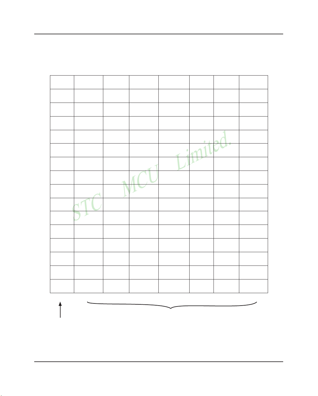
STC MCU Limited.
Mobile:(86)13922809991 Tel:86-755-82948412 Fax:86-755-82905966
STC MCU Limited.
website:www.STCMCU.com
53
www.STCMCU.com
3.3 Special Function Registers
Bit Addressable
Non Bit Addressable
3.3.1 Special Function Registers Address Map
0/8 1/9 2/A 3/B 4/C 5/D 6/E 7/F
0F8H
CH CCAP0H CCAP1H
0FFH
0000,0000 0000,0000 0000,0000
0F0H
B
PCA_PWM0 PCA_PWM1
0F7H
0000,0000 xxxx,xx00 xxxx,xx00
0E8H
CL CCAP0L CCAP1L
0EFH
0000,0000 0000,0000 0000,0000
0E0H
ACC WDT_CONR ISP_DATA ISP_ADDRH ISP_ADDRL ISP_CMD ISP_TRIG ISP_CONTR
0E7H
0000,0000 0x00,0000 1111,1111 0000,0000 0000,0000 xxxx,xx00 xxxx,xxxx 0000,1000
0D8H
CCON CMOD CCAPM0 CCAPM1 CCAPM2 CCAPM3
0DFH
00xx,0000 0xxx,x000 x000,0000 x000,0000 x000,0000 x000,0000
0D0H
PSW
0D7H
0000,0000
0C8H 0CFH
0C0H
ADC_CONTR
ADC_DATA
CLK_DIV
0C7H
0000,0000
0000,0000 xxxx,x000
0B8H
IP SADEN
0BFH
x000,0000
0B0H
P3 P3M0 P3M1 IPH
0B7H
1x11,1111 0000,0000 0000,0000 x000,0000
0A8H
IE SADDR
0AFH
0000,0000
0A0H
Don't use
0A7H
098H
SCON SBUF
09FH
0000,0000 xxxx,xxxx
090H
P1 P1M0 P1M1
097H
1111,1111 0000,0000 0000,0000
088H
TCON TMOD TL0 TL1 TH0 TH1 AUXR
WAKE_CLKO
08FH
0000,0000 0000,0000 0000,0000 0000,0000 0000,0000 0000,0000 0000,00xx 0000,xx00
080H
SP DPL DPH SPSTAT SPCTL SPDAT PCON
087H
0000,0111 0000,0000 0000,0000 00xx,xxxx 0000,0100 0000,0000 0011,0000
0/8 1/9 2/A 3/B 4/C 5/D 6/E 7/F
Page 54

STC MCU Limited.
Mobile:(86)13922809991 Tel:086-755-82948412
Fax:86-755-82905966
STC MCU Limited. website:www.STCMCU.com
54
www.STCMCU.com
3.3.2 Special Function Registers Bits Description
Symbol Description Address Bit Address and Symbol
MSB LSB
Value after
Power-on or
Reset
P0 Port 0 80H
P0.7 P0.6 P0.5 P0.4 P0.3 P0.2 P0.1 P0.0
1111 1111B
SP Stack Pointer 81H 0000 0111B
DPTR
DPL
DPH
Data Pointer Low 82H 0000 0000B
Data Pointer High 83H 0000 0000B
SPSTAT SPI Status register 84H
SPIF WCOL - - - - - -
00xx xxxxB
SPCTL SPI control register 85H
SSIG SPEN DORD MSTR CPOL CPHA SPR1 SPR0
0000 0100B
SPDAT SPI Data register 86H 0000 0000B
PCON Power Control 87H
SMOD SMOD0 LVDF POF GF1 GF0 PD IDL
0011 0000B
TCON Timer Control 88H
TF1 TR1 TF0 TR0 IE1 IT1 IE0 IT0
0000 0000B
TMOD Timer Mode 89H
GATE
C/T
M1 M0 GATE
C/T
M1 M0
0000 0000B
TL0 Timer Low 0 8AH 0000 0000B
TL1 Timer Low 1 8BH 0000 0000B
TH0 Timer High 0 8CH 0000 0000B
TH1 Timer High 1 8DH 0000 0000B
AUXR Auxiliary register 8EH
T0x12 T1x12
UART_M0x6
EADCI ESPI ELVDI
- -
0000 00xxB
WAKE_CLKO
CLK_Output
Power down
Wake-up control
register
8FH
PCAWAKEUP RXD_PIN_IE T1_PIN_IE T0_PIN_IE - - T1CLKO T0CLKO
0000 xx00B
P1 Port 1 90H
P1.7 P1.6 P1.5 P1.4 P1.3 P1.2 P1.1 P1.0
1111 1111B
P1M0 P1 configuration 0 91H 0000 0000B
P1M1 P1 configuration 1 92H 0000 0000B
SCON Serial Control 98H
SM0/FE SM1 SM2 REN TB8 RB8 TI RI
0000 0000B
SBUF Serial Buffer 99H xxxx xxxxB
P2 Port 2 A0H
P2.7 P2.6 P2.5 P2.4 P2.3 P2.2 P2.1 P2.0
1111 1111B
IE Interrupt Enable A8H
EA EPCA_LVD EADC_SPI ES ET1 EX1 ET0 EX0
0000 0000B
SADDR Slave Address A9H 0000 0000B
P3 Port 3 B0H
P3.7 - P3.5 P3.4 P3.3 P3.2 P3.1 P3.0
1x11 1111B
P3M0 P2 configuration 0 B1H 0000 0000B
P3M1 P3 configuration 1 B2H 0000 0000B
IPH
Interrupt Priority
High
B7H
-
PPCA_LVDH PADC_SPIH
PSH PT1H PX1H PT0H PX0H
x000 0000B
IP
Interrupt Priority
Low
B8H
-
PPCA_LVD PADC_SPI
PS PT1 PX1 PT0 PX0
x000 0000B
SADEN
Slave Address
Mask
B9H 0000 0000B
ADC_CONTR
ADC Control C5H
ADC_POWER SPEED1 SPEED0 ADC_FLAG ADC_START CHS2 CHS1 CHIS0
0000 0000B
ADC_DATA
ADC Result High C6H 0000 0000B
Page 55

STC MCU Limited.
Mobile:(86)13922809991 Tel:86-755-82948412 Fax:86-755-82905966
STC MCU Limited.
website:www.STCMCU.com
55
www.STCMCU.com
Symbol Description Address Bit Address and Symbol
MSB LSB
Value after
Power-on or
Reset
CLK_DIV Clock Divder C7h
- - - - - CLKS2 CLKS1 CLKS0
xxxx x000B
PSW
Program Status
Word
D0H
CY AC F0 RS1 RS0 OV F1 P
0000 0000B
CCON
PCA Control
Register
D8H
CF CR - - - - CCF1 CCF0
00xx xx00B
CMOD PCA Mode Register D9H
CIDL - - - - CPS1 CPS0 ECF
00xx x000B
CCAPM0
PCA Module 0
Mode Register
DAH
- ECOM0 CAPP0 CAPN0 MAT0 TOG0 PWM0 ECCF0
x000 0000B
CCAPM1
PCA Module 1
Mode Register
DBH
- ECOM1 CAPP1 CAPN1 MAT1 TOG1 PWM1 ECCF1
x000 0000B
ACC Accumulator E0H 0000 0000B
WDT_CONTR
Watch-Dog-Timer
Control Register
E1H
WDT_FLAG-EN_WDT CLR_WDT IDLE_WDT PS2 PS1 PS0
xx00 0000B
ISP_DATA
ISP/IAP Flash Data
Register
E2H 1111 1111B
ISP_ADDRH
ISP/IAP Flash
Address High
E3H 0000 0000B
ISP_ADDRL
ISP/IAP Flash
Address Low
E4H 0000 0000B
ISP_CMD
ISP/IAP Flash
Command Register
E5H
- - - - - - MS1 MS0
xxxx x000B
ISP_TRIG
ISP/IAP Flash
Command Trigger
E6H xxxx xxxxB
ISP_CONTR
ISP/IAP Control
Register
E7H
IAPEN SWBS SWRST CMD_FAIL - WT2 WT1 WT0
0000 x000B
CL
PCA Base Timer
Low
E9H 0000 0000B
CCAP0L
PCA module 0
capture register low
EAH 0000 0000B
CCAP1L
PCA module 1
capture register low
EBH 0000 0000B
B B Register F0H 0000 0000B
PCA_PWM0
PCA PWM mode
auxiliary register 1
F2H
- - - - - - EPC0H EPC0L
xxxx xx00B
PCA_PWM1
PCA PWM mode
auxiliary register 1
F3H
- - - - - - EPC1H EPC1L
xxxx xx00B
CH
PCA Base Timer
High
F9H 0000 0000B
CCAP0H
PCA module 0
capture register high
FAH 0000 0000B
CCAP1H
PCA module 1
capture register high
FBH 0000 0000B
Page 56

STC MCU Limited.
Mobile:(86)13922809991 Tel:086-755-82948412 Fax:86-755-82905966
STC MCU Limited. website:www.STCMCU.com
56
www.STCMCU.com
Accumulator
ACC is the Accumulator register. The mnemonics for accumulator-specific instructions, however, refer to the
accumulator simply as A.
B-Register
The B register is used during multiply and divide operations. For other instructions it can be treated as another
scratch pad register.
Stack Pointer
The Stack Pointer register is 8 bits wide. It is incrementde before data is stored during PUSH and CALL
executions. While the stack may reside anywhee in on-chip RAM, the Stack Pointer is initialized to 07H after a
reset.
Therefore, the first value pushed on the stack is placed at location 0x08, which is also the first
register (R0) of register bank 1. Thus, if more than one register bank is to be used, the SP should be
initialized to a location in the data memory not being used for data storage. The stack depth can extend
up to 256 bytes.
Some common SFRs of standard 8051 are shown as below.
Program Status Word(PSW)
The program status word(PSW) contains several status bits that reflect the current state of the CPU. The PSW,
shown below, resides in the SFR space. It contains the Carry bit, the Auxiliary Carry(for BCD operation), the two
register bank select bits, the Overflow flag, a Parity bit and two user-definable status flags.
The Carry bit, other than serving the function of a Carry bit in arithmetic operations, also serves as the
“Accumulator” for a number of Boolean operations.
The bits RS0 and RS1 are used to select one of the four register banks shown in the previous page. A number of
instructions refer to these RAM locations as R0 through R7.
The Parity bit reflects the number of 1s in the Accumulator. P=1 if the Accumulator contains an odd number of 1s
and otherwise P=0.
Data Pointer Register (DPTR)
The Data Pointer (DPTR) consists of a high byte (DPH) and a low byte (DPL). Its intended function is to hold a
16-bit address. It may be manipulated as a 16-bit register or as two independent 8-bit registers.
Page 57

STC MCU Limited.
Mobile:(86)13922809991 Tel:86-755-82948412 Fax:86-755-82905966
STC MCU Limited.
website:www.STCMCU.com
57
www.STCMCU.com
PSW register
SFR name Address bit B7 B6 B5 B4 B3 B2 B1 B0
PSW D0H name CY AC F0 RS1 RS0 OV F1 P
CY : Carry flag.
This bit is set when the last arithmetic operation resulted in a carry (addition) or a borrow
(subtrac-tion). It is cleared to logic 0 by all other arithmetic operations.
AC : Auxilliary Carry Flag.(For BCD operations)
This bit is set when the last arithmetic operation resulted in a carry into (addition) or a borrow
from (subtraction) the high order nibble. It is cleared to logic 0 by all other arithmetic operations
F0 : Flag 0.(Available to the user for general purposes)
RS1: Register bank select control bit 1.
RS0: Register bank select control bit 0.
[RS1 RS0] select which register bank is used during register accesses
RS1 RS0
Working Register Bank
(R0~R7) and Address
0 0 Bank 0(00H~07H)
0 1 Bank 1(08H~0FH)
1 0 Bank 2(10H~17H)
1 1 Bank 3(18H~1FH)
OV : Overflow flag.
This bit is set to 1 under the following circumstances:
• An ADD, ADDC, or SUBB instruction causes a sign-change overflow.
• A MUL instruction results in an overflow (result is greater than 255).
• A DIV instruction causes a divide-by-zero condition.
The OV bit is cleared to 0 by the ADD, ADDC, SUBB, MUL, and DIV instructions in all other
cases.
F1 : Flag 1. User-defined flag.
P : Parity flag.
This bit is set to logic 1 if the sum of the eight bits in the accumulator is odd and cleared if the
sum is even.
Page 58

STC MCU Limited.
Mobile:(86)13922809991 Tel:086-755-82948412 Fax:86-755-82905966
STC MCU Limited. website:www.STCMCU.com
58
www.STCMCU.com
Chapter 4. Configurable I/O Ports of STC12C2052AD series
4.1 I/O Ports Configurations
All I/O ports of STC12C2052AD may be independently configured to one of four modes by setting the
corresponding bit in two mode registers PxMn (x= 0 ~ 3, n = 0, 1).The four modes are quasi-bidirectional (standard
8051 port output), push-pull output, input-only or open-drain output. All port pins default to quasi-bidirectional
after reset. Each one has a Schmitt-triggered input for improved input noise rejection. Any port can drive 20mA
current, but the whole chip had better drive lower than 90mA current.
Configure I/O ports mode
P3 Configure <P3.7, P3.6, P3.5, P3.4, P3.3, P3.2, P3.1, P3.0 port> (P3 address address:B0H))
P3M0[7 : 0] P3M1 [7 : 0] I/O ports Mode
0 0
quasi_bidirectional(standard 8051 I/O port output) ,
Because of manufactured error, the actual pull-up current is 250uA ~ 150uA
0 1
push-pull output(strong pull-up output,current can be up to 20mA, resistors
need to be added to restrict current
1 0 input-only (high-impedance )
1 1
Open Drain,internal pull-up resistors should be disabled and external
pull-up resistors need to join.
Example: MOV P3M0, #10100000B
MOV P3M1, #10010000B
;P3.7 in Open Drain mode, P3.5 in high-impedance input, P3.4 in strong push-pull output, P3.3/P3.2/P3.1/P3.0
in quasi_bidirectional/weak pull-up/weak pull-up
P1M0[7 : 0] P1M1 [7 : 0] I/O ports Mode
0 0
quasi_bidirectional(standard 8051 I/O port output) ,
Because of manufactured error, the actual pull-up current is 250uA ~ 150uA
0 1
push-pull output(strong pull-up output,current can be up to 20mA, resistors
need to be added to restrict current
1 0 input-only (high-impedance )
1 1
Open Drain,internal pull-up resistors should be disabled and external
pull-up resistors need to join.
Example: MOV P1M0, #10100000B
MOV P1M1, #11000000B
;P1.7 in Open Drain mode, P1.6 in strong push-pull output, P1.5 in high-impedance input, P1.4/P1.3/P1.2/
P1.1/P1.0 in quasi_bidirectional/weak pull-up/weak pull-up
P1 Configure <P1.7, P1.6, P1.5, P1.4, P1.3, P1.2, P1.1, P1.0 port> (P1 address address:90H))
Page 59

STC MCU Limited.
Mobile:(86)13922809991 Tel:86-755-82948412 Fax:86-755-82905966
STC MCU Limited.
website:www.STCMCU.com
59
www.STCMCU.com
Some SFRs related with I/O ports are listed below.
P3 register (bit addressable)
SFR name Address bit B7 B6 B5 B4 B3 B2 B1 B0
P3 B0H name P3.7 P3.6 P3.5 P3.4 P3.3 P3.2 P3.1 P3.0
P3 register could be bit-addressable and set/cleared by CPU. And P3.7~P3.0 coulde be set/cleared by CPU.
P3M0 register (non bit addressable)
SFR name Address bit B7 B6 B5 B4 B3 B2 B1 B0
P3M0 B1H name P3M0.7 P3M0.6 P3M0.5 P3M0.4 P3M0.3 P3M0.2 P3M0.1 P3M0.0
P3M1 register (non bit addressable)
SFR name Address bit B7 B6 B5 B4 B3 B2 B1 B0
P3M1 B2H name P3M1.7 P3M1.6 P3M1.5 P3M1.4 P3M1.3 P3M1.2 P3M1.1 P3M1.0
P1 register (bit addressable)
SFR name Address bit B7 B6 B5 B4 B3 B2 B1 B0
P1 90H name P1.7 P1.6 P1.5 P1.4 P1.3 P1.2 P1.1 P1.0
P1 register could be bit-addressable and set/cleared by CPU. And P1.7~P1.0 coulde be set/cleared by CPU.
P1M0 register (non bit addressable)
SFR name
Address bit B7 B6 B5 B4 B3 B2 B1 B0
P1M0
91H name P1M0.7 P1M0.6 P1M0.5 P1M0.4 P1M0.3 P1M0.2 P1M0.1 P1M0.0
P1M1 register (non bit addressable)
SFR name
Address bit B7 B6 B5 B4 B3 B2 B1 B0
P1M1
92H name P1M1.7 P1M1.6 P1M1.5 P1M0.4 P1M1.3 P1M1.2 P1M1.1 P1M1.0
Page 60

STC MCU Limited.
Mobile:(86)13922809991 Tel:086-755-82948412 Fax:86-755-82905966
STC MCU Limited. website:www.STCMCU.com
60
www.STCMCU.com
4.2.1 Quasi-bidirectional I/O
Port pins in quasi-bidirectional output mode function similar to the standard 8051 port pins. A quasi-bidirectional
port can be used as an input and output without the need to reconfigure the port. This is possible because when
the port outputs a logic high, it is weakly driven, allowing an external device to pull the pin low. When the pin
outputs low, it is driven strongly and able to sink a large current. There are three pull-up transistors in the quasibidirectional output that serve different purposes.
One of these pull-ups, called the “very weak” pull-up, is turned on whenever the port register for the pin contains
a logic “1”. This very weak pull-up sources a very small current that will pull the pin high if it is left floating.
A second pull-up, called the “weak” pull-up, is turned on when the port register for the pin contains a logic
“1” and the pin itself is also at a logic “1” level. This pull-up provides the primary source current for a quasibidirectional pin that is outputting a 1. If this pin is pulled low by the external device, this weak pull-up turns off,
and only the very weak pull-up remains on. In order to pull the pin low under these conditions, the external device
has to sink enough current to over-power the weak pull-up and pull the port pin below its input threshold voltage.
The third pull-up is referred to as the “strong” pull-up. This pull-up is used to speed up low-to-high transitions on
a quasi-bidirectional port pin when the port register changes from a logic “0” to a logic “1”. When this occurs, the
strong pull-up turns on for two CPU clocks, quickly pulling the port pin high.
Vcc
2 clock
delay
Vcc Vcc
PORT
PIN
Weak
Very weak
Strong
PORT
LATCH DATA
INPUT
DATA
Quasi-bidirectional output
4.2 I/O ports Modes
Page 61

STC MCU Limited.
Mobile:(86)13922809991 Tel:86-755-82948412 Fax:86-755-82905966
STC MCU Limited.
website:www.STCMCU.com
61
www.STCMCU.com
4.2.4 Open-drain Output
The open-drain output configuration turns off all pull-ups and only drives the pull-down transistor
of the port pin when the port register contains a logic “0”. To use this configuration in application, a
port pin must have an external pull-up, typically tied to VCC. The input path of the port pin in this
configuration is the same as quasi-bidirection mode.
PORT
PIN
PORT
LATCH DATA
INPUT
DATA
Open-drain output
4.2.3 Input-only (High-Impedance)Mode
The input-only configuration is a Schmitt-triggered input without any pull-up resistors on the pin.
PORT
PIN
INPUT
DATA
Input-only Mode
4.2.2 Push-pull Output
The push-pull output configuration has the same pull-down structure as both the open-drain and the quasibidirectional output modes, but provides a continuous strong pull-up when the port register conatins a logic “1”.
The push-pull mode may be used when more source current is needed from a port output. In addition, input path
of the port pin in this configuration is also the same as quasi-bidirectional mode.
Vcc
PORT
PIN
PORT
LATCH DATA
INPUT
DATA
Push-pull output
Page 62

STC MCU Limited.
Mobile:(86)13922809991 Tel:086-755-82948412 Fax:86-755-82905966
STC MCU Limited. website:www.STCMCU.com
62
www.STCMCU.com
4.3 I/O port application notes
Traditional 8051 access I/O (signal transition or read status) timing is 12 clocks, STC12C2052AD series MCU is
4 clocks. When you need to read an external signal, if internal output a rising edge signal, for the traditional 8051,
this process is 12 clocks, you can read at once, but for STC12C2052AD series MCU, this process is 4 clocks,
when internal instructions is complete but external signal is not ready, so you must delay 1~2 nop operation.
When MCU is connected to a SPI or I2C or other open-drain peripherals circuit, you need add a 10K pull-up
resistor.
Some IO port connected to a PNP transistor, but no pul-up resistor. The correct access method is IO port pull-up
resistor and transistor base resistor should be consistent, or IO port is set to a strongly push-pull output mode.
Using IO port drive LED directly or matrix key scan, needs add a 470ohm to 1Kohm resistor to limit current.
4.4 Typical transistor control circuit
If I/O is configed as “weak” pull-up, you should add a external pull-up resistor R1(3.3K~10K ohm). If no pull-up
resistor R1, proposal to add a 15K ohm series resistor R2 at least or config I/O as “push-pull” mode.
common I/O port
R1
10K(3.3K~10K)
R3
R2
15K(3.3K~15K)
4.5 Typical diode control circuit
I/O
1K
For weak pull-up / quasi-bidirectional I/O, use sink current drive LED, current limiting resistor as greater than 1K
ohm, minimum not less than 470 ohm.
I/O
1K
For push-pull / strong pull-up I/O, use drive current drive LED.
Vcc
Vcc
Vcc
Page 63

STC MCU Limited.
Mobile:(86)13922809991 Tel:86-755-82948412 Fax:86-755-82905966
STC MCU Limited.
website:www.STCMCU.com
63
www.STCMCU.com
4.6 3V/5V hybrid system
When STC12C2052AD series 5V MCU connect to 3.3V peripherals. To prevent the 3.3V device can not afford to
5V voltage, the 5V MCU corresponding I/O should first add a 330 ohm current limiting resistor to 3.3 device I/O
ports. And in intialization of procedures the 5V MCU corresponding I/O is set to open drain mode, disconnect the
internal pull-up resistor, the corresponding 3.3V device I/O port add 10K ohm external pull-up resistor to the 3.3V
device VCC, so high level to 3.3V and low to 0V, which can proper functioning
MCU common I/O
external input signal
When STC12LE2052AD series 3V MCU connect to 5V peripherals. To prevent the 3V MCU can not afford to 5V
voltage, if the corresponding I/O port as input port, the port may be in an isolation diode in series, isolated highvoltage part. When the external signal is higher than MCU operating voltage, the diode cut-off, I/O have been
pulled high by the internal pull-up resistor; when the external signal is low, the diode conduction, I/O port voltage
is limited to 0.7V, it’s low signal to MCU.
5V MCU I/O port
10K
330
3.3V device I/O port
3.3V
When STC12LE2052AD series 3V MCU connect to 5V peripherals. To prevent the 3V MCU can not afford to
5V voltage, if the corresponding I/O port as output port, the port may be connect a NPN transistor to isolate highvoltage part. The circuit is shown as below.
common I/O port
10K
2K
5V
1
0
5V device I/O port
1
0
Page 64

STC MCU Limited.
Mobile:(86)13922809991 Tel:086-755-82948412 Fax:86-755-82905966
STC MCU Limited. website:www.STCMCU.com
64
www.STCMCU.com
4.7 How to make I/O port low after MCU reset
Traditional 8051 MCU power-on reset, the general IO port are weak pull-high output, while many practical
applications require IO port remain low level after power-on reset, otherwise the system malfunction would be
generated. For STC12C2052AD series MCU, IO port can add a pull-down resistor (1K/2K/3K), so that when
power-on reset, although a weak internal pull-up to make MCU output high, but because of the limited capacity
of the internal pull-up, it can not pull-high the pad, so this IO port is low level after power-on reset. If the I/O port
need to drive high, you can set the IO model as the push-pull output mode, while the push-pull mode the drive
current can be up to 20mA, so it can drive this I/O high.
I/O
1K/2K/3K
More then 470ohm
4.8 I/O status while PWM outputing
When I/O is used as PWM port, it’s status as bellow:
Before PWM output While PWM outputing
Quasi-bidirectional Push-Pull (Strong pull-high need 1K~10K limiting resistor)
Push-Pull Push-Pull (Strong pull-high need 1K~10K limiting resistor)
Input ony (Floating) PWM Invalid
Open-drain Open-drain
common I/O port
To load
current limiting resistor between 10K and 1K
Page 65

STC MCU Limited.
Mobile:(86)13922809991 Tel:86-755-82948412 Fax:86-755-82905966
STC MCU Limited.
website:www.STCMCU.com
65
www.STCMCU.com
4.9 I/O drive LED application circuit
R1aR2bR3cR4dR5eR6fR7gR8
dp
COM1
COM2
COM3
COM4
I/O
I/O
I/O
I/O
R1
471
R2
471
R3
471
R4
471
I/O
I/O
I/O
I/O
I/O
I/O
I/O
I/O
LED4
a
R5
I/O
b
R6
I/O
c
R7
I/O
d
R8
I/O
e
R9
I/O
f
R10
I/O
g
R11
I/O
dp
R12
I/O
I/O
LED3
I/O
LED2
I/O
LED1
I/O
a
b
c
d e
f
g
dp
COM1
LED4
R4
4K7
LED3
R3
4K7
LED2
R2
4K7
LED1
R1
4K7
VCC
COM2 COM3 COM4
470ohm*8
I/O dynamic scan driver 4 groups of
digital tube Cathode circuit
I/O dynamic scan driver 4 groups of
digital tube anode circuit
1Kohm*8
32
31
30
29
28
27
26
25
24
23
22
21
20
19
18
17
VCC
P2.1
P1.7/SCLK/ADC7
P1.4/SS/ADC4
P1.3/ADC3
P1.2/ADC2
P1.1/ADC1/CLKOUT1
P1.6/MISO/ADC6
P1.5/MOSI/ADC5
P2.0/PCA2/PWM2
P1.0/ADC0/CLKOUT0
P3.7/PCA0/PWM0
P2.7
P2.6
RST
TxD/P3.1
XTAL2
XTAL1
Gnd
RxD/P3.0
INT1/P3.3
ECI/T0/P3.4
PWM1/PCA1/T1/P3.5
INT0/P3.2
P2.2
P2.3
PWM3/PCA3/P2.4
P2.5
1
2
3
4
5
6
7
8
9
10
11
12
13
14
15
16
SOP-32
P0.0
P0.1
P0.3
P0.2
Page 66

STC MCU Limited.
Mobile:(86)13922809991 Tel:086-755-82948412 Fax:86-755-82905966
STC MCU Limited. website:www.STCMCU.com
66
www.STCMCU.com
SEG1
SEG2
SEG3
SEG4
SEG5
SEG6
SEG7
SEG8
COM1
COM2
COM3
COM4
SEG1
SEG2
SEG3
SEG4
SEG5
SEG6
SEG7
SEG8
COM1
COM2
COM3
COM4
SEG1
I/O
SEG2
I/O
SEG3
I/O
SEG4
I/O
SEG5
I/O
SEG6
I/O
SEG7
I/O
SEG8
I/O
COM1
I/O
I/O
I/O
I/O
LCD4X8
COM2
COM3
COM4
COM1
R1
100K
R2
100K
R3
100K
R4
100K
R5
100K
R6
100K
R7
100K
R8
100K
VCC
COM2
COM3
COM4
How to light on the LCD pixels:
When the pixels corresponding COM-side and SEG-side voltage difference is greater than 1/2VCC, this
pixel is lit, otherwise off
Contrl SEG-side (Segment) :
I/O direct drive Segment lines, control Segment output high-level (VCC) or low-level (0V).
Contrl COM-side (Common) :
I/O port and two 100K dividing resistors jointly controlled Common line, when the IO output "0", the
Common-line is low level (0V), when the IO push-pull output "1", the Common line is high level (VCC),
when IO as high-impedance input, the Common line is 1/2VCC.
SEG1
SEG2
SEG3
SEG4
SEG5
SEG6
SEG7
SEG8
COM1
COM2
COM3
COM4
SEG1
SEG2
SEG3
SEG4
SEG5
SEG6
SEG7
SEG8
COM1
COM2
COM3
COM4
SEG1
I/O
SEG2
I/O
SEG3
I/O
SEG4
I/O
SEG5
I/O
SEG6
I/O
SEG7
I/O
SEG8
I/O
COM1
I/O
I/O
I/O
I/O
LCD4X8
COM2
COM3
COM4
COM1
R1
100K
R2
100K
R3
100K
R4
100K
R5
100K
R6
100K
R7
100K
R8
100K
VCC
COM2
COM3
COM4
Before MCU enter Power_Down
mode, the I/O output high level,
then Common side will have no
leakage current
I/O control
4.10 I/O immediately drive LCD application circuit
1/2 BIAS
1/2 BIAS
Page 67

STC MCU Limited.
Mobile:(86)13922809991 Tel:86-755-82948412 Fax:86-755-82905966
STC MCU Limited.
website:www.STCMCU.com
67
www.STCMCU.com
R6
8.2
K
sw6
R5
5.4
K
sw5
R4
3.3
K
sw4
R3
1.8
K
sw3
R2
sw2sw1
R1
10K
+5V
ADCx
47pF
0
0`0.5
0.5`1
1`1.5
1.5`2.0
2.0`2.5
R1
520
sw2sw1
R0
10K
+5V
ADCx
47pF
0
R2
1.2K
sw3
R3
1.6K
sw4
R4
1.8K
sw5
R5
3K
sw6
R6
4K
sw7
R7
6.5
sw8
R8
10K
sw9
R9
30K
sw10
R10
100K
sw11
4.11 Using A/D Conversion to scan key application circuit
This circuit can achieve a signle key
or combin key scan, resistance need to
configure the actual needs
This circuit use 10 keys spaced partial pressure, for each key, range
of allowed error is +/-0.25V, it can effectively avoid failure of key
detection because of resistance or temperature drift. If the requested
key detection more stable and reliable, can reduce the number of
buttons, to relax the voltage range of each key
28
27
26
25
24
23
22
21
20
19
18
17
16
15
Vcc
P2.1
P2.7
P1.7/ADC7
P1.5/ADC5
P1.4/ADC4
P1.3/ADC3
Gnd
P1.1/ADC1/CLKOUT1
P1.0/ADC0/CLKOUT0
P1.2/ADC2
P2.2
RST
P2.5
1
2
3
4
5
6
7
8
9
10
11
12
13
14
P1.6/ADC6
P2.4
P2.0
P3.7/PCA0/PWM0
SOP-28/SKDIP-28
RxD/P3.0
TxD/P3.1
XTAL2
XTAL1
INT0/P3.2
INT1/P3.3
PWM1/PCA1/T1/P3.5
ECI/T0/P3.4
P2.3
P2.6
Page 68

STC MCU Limited.
Mobile:(86)13922809991 Tel:086-755-82948412 Fax:86-755-82905966
STC MCU Limited. website:www.STCMCU.com
68
www.STCMCU.com
Chapter 5. Instruction System
Register-Specific Instruction
Some instructions are specific to a certain register. For example, some instructions always operate on the
accumulator or data pointer,etc. No address byte is needed for such instructions. The opcode itself does it.
Index Addressing
Only program memory can be accessed with indexed addressing and it can only be read. This addressing mode is
intended for reading look-up tables in program memory. A 16-bit base register(either DPTR or PC) points to the
base
of the table, and the accumulator is set up with the table entry number. Another type of indexed
addressing is used in the conditional jump instruction.
In conditional jump, the destination address is computed as the sum of the base pointer and the
accumulator.
5.1 Addressing Modes
Addressing modes are an integral part of each computer's instruction set. They allow specifyng the source or
destination of data in different ways, depending on the programming situation. There are five modes available:
Immediate
Direct
Indirect
Register
Indexed
Immediate Constant(IMM)
The value of a constant can follow the opcode in the program memory. For example,
MOV A, #70H
loads the Accumulator with the hex digits 70. The same number could be specified in decimal number as 112.
Direct Addressing(DIR)
In direct addressing the operand is specified by an 8-bit address field in the instruction. Only 128 lowest bytes of
internal data RAM and SFRs can be direct addressed.
Indirect Addressing(IND)
In indirect addressing the instruction specified a register which contains the address of the operand. Both internal
and external RAM can be indirectly addressed.
The address register for 8-bit addresses can be R0 or R1 of the selected bank, or the Stack Pointer.
The address register for 16-bit addresses can only be the 16-bit data pointer register – DPTR.
Register Instruction(REG)
The register banks, containing registers R0 through R7, can be accessed by certain instructions which carry a 3-bit
register specification within the opcode of the instruction. Instructions that access the registers this way are code
efficient because this mode eliminates the need of an extra address byte. When such instruction is executed, one
of the eight registers in the selected bank is accessed.
•
•
•
•
•
Page 69

STC MCU Limited.
Mobile:(86)13922809991 Tel:86-755-82948412 Fax:86-755-82905966
STC MCU Limited.
website:www.STCMCU.com
69
www.STCMCU.com
5.2 Instruction Set Summary
Mnemonic Description Byte
Execution clocks
of 12T MCU
Execution clocks
of STC 1T MCU
Efficiency
improved
ARITHMETIC OPERATIONS
ADD A, Rn Add register to Accumulator 1 12 2 6x
ADD A, direct Add ditect byte to Accumulator 2 12 3 4x
ADD A, @Ri Add indirect RAM to Accumulator 1 12 3 4x
ADD A, #data Add immediate data to Accumulator 2 12 2 6x
ADDC A, Rn Add register to Accumulator with Carry 1 12 2 6x
ADDC A, direct Add direct byte to Accumulator with Carry 2 12 3 4x
ADDC A, @Ri Add indirect RAM to Accumulator with Carry 1 12 3 4x
ADDC A, #data Add immediate data to Acc with Carry 2 12 2 6x
SUBB A, Rn Subtract Register from Acc wih borrow 1 12 2 6x
SUBB A, direct Subtract direct byte from Acc with borrow 2 12 3 4x
SUBB A, @Ri Subtract indirect RAM from ACC with borrow 1 12 3 4x
SUBB A, #data Substract immediate data from ACC with borrow 2 12 2 6x
INC A Increment Accumulator 1 12 2 6x
INC Rn Increment register 1 12 3 4x
INC direct Increment direct byte 2 12 4 3x
INC @Ri Increment direct RAM 1 12 4 3x
DEC A Decrement Accumulator 1 12 2 6x
DEC Rn Decrement Register 1 12 3 4x
DEC direct Decrement direct byte 2 12 4 3x
DEC @Ri Decrement indirect RAM 1 12 4 3x
INC DPTR Increment Data Pointer 1 24 1 24x
MUL AB Multiply A & B 1 48 4 12x
DIV AB Divde A by B 1 48 5 9.6x
DA A Decimal Adjust Accumulator 1 12 4 3x
The STC MCU instructions are fully compatible with the standard 8051's,which are divided among five functional
groups:
Arithmetic
Logical
Data transfer
Boolean variable
Program branching
The following tables provides a quick reference chart showing all the 8051 and STC 1T MCU instructions. Once
you are familiar with the instruction set, this chart should prove a handy and quick source of reference.
•
•
•
•
•
Execution Clocks of
Conventional 12T 8051
Execution Clocks of
STC12C2052AD series
Page 70

STC MCU Limited.
Mobile:(86)13922809991 Tel:086-755-82948412 Fax:86-755-82905966
STC MCU Limited. website:www.STCMCU.com
70
www.STCMCU.com
Mnemonic Description Byte
Execution clocks
of 12T MCU
Execution clocks
of STC 1T MCU
Efficiency
improved
LOGICAL OPERATIONS
ANL A, Rn AND Register to Accumulator 1 12 2 6x
ANL A, direct AND direct btye to Accumulator 2 12 3 4x
ANL A, @Ri AND indirect RAM to Accumulator 1 12 3 4x
ANL A, #data AND immediate data to Accumulator 2 12 2 6x
ANL direct, A AND Accumulator to direct byte 2 12 4 3x
ANL direct, #data AND immediate data to direct byte 3 24 4 6x
ORL A, Rn OR register to Accumulator 1 12 2 6x
ORL A,direct OR direct byte to Accumulator 2 12 3 4x
ORL A,@Ri OR indirect RAM to Accumulator 1 12 3 4x
ORL A, #data OR immediate data to Accumulator 2 12 2 6x
ORL direct, A OR Accumulator to direct byte 2 12 4 3x
ORL direct,#data OR immediate data to direct byte 3 24 4 6x
XRL A, Rn Exclusive-OR register to Accumulator 1 12 2 6x
XRL A, direct Exclusive-OR direct byte to Accumulator 2 12 3 4x
XRL A, @Ri Exclusive-OR indirect RAM to
Accumulator
1 12 3 4x
XRL A, #data Exclusive-OR immediate data to
Accumulator
2 12 2 6x
XRL direct, A Exclusive-OR Accumulator to direct byte 2 12 4 3x
XRL direct,#data Exclusive-OR immediate data to direct
byte
3 24 4 6x
CLR A Clear Accumulator 1 12 1 12x
CPL A Complement Accumulator 1 12 2 6x
RL A Rotate Accumulator Left 1 12 1 12x
RLC A Rotate Accumulator Left through the Carry 1 12 1 12x
RR A Rotate Accumulator Right 1 12 1 12x
RRC A Rotate Accumulator Right through the
Carry
1 12 1 12x
SWAP A Swap nibbles within the Accumulator 1 12 1 12x
Page 71

STC MCU Limited.
Mobile:(86)13922809991 Tel:86-755-82948412 Fax:86-755-82905966
STC MCU Limited.
website:www.STCMCU.com
71
www.STCMCU.com
Mnemonic Description Byte
Execution clocks
of 12T MCU
Execution clocks
of STC 1T MCU
Efficiency
improved
DATA TRANSFER
MOV A, Rn Move register to Accumulator 1 12 1 12x
MOV A, direct Move direct byte to Accumulator 2 12 2 6x
MOV A,@Ri Move indirect RAM to 1 12 2 6x
MOV A, #data Move immediate data to Accumulator 2 12 2 6x
MOV Rn, A Move Accumulator to register 1 12 2 6x
MOV Rn, direct Move direct byte to register 2 24 4 6x
MOV Rn, #data Move immediate data to register 2 12 2 6x
MOV direct, A Move Accumulator to direct byte 2 12 3 4x
MOV direct, Rn Move register to direct byte 2 24 3 8x
MOV direct,direct Move direct byte to direct 3 24 4 6x
MOV direct, @Ri Move indirect RAM to direct byte 2 24 4 6x
MOV direct, #data Move immediate data to direct byte 3 24 3 8x
MOV @Ri, A Move Accumulator to indirect RAM 1 12 3 4x
MOV @Ri, direct Move direct byte to indirect RAM 2 24 4 6x
MOV @Ri, #data Move immediate data to indirect RAM 2 12 3 4x
MOV DPTR, #data16 Move immdiate data to indirect RAM 2 24 3 8x
MOVC A, @A+DPTR Move Code byte relative to DPTR to Acc 1 24 4 6x
MOVC A, @A+PC Move Code byte relative to PC to Acc 1 24 4 6x
MOVX A, @Ri Move External RAM(8-bit addr) to Acc 1 24 3 8x
MOVX @Ri, A Move Acc to External RAM(8-bit addr) 1 24 4 6x
MOVX A, @DPTR Move External RAM(16-bit addr) to Acc 1 24 3 8x
MOVX @DPTR, A Move Acc to External RAM (16-bit addr) 1 24 3 8x
PUSH direct Push direct byte onto stack 2 24 4 6x
POP direct POP direct byte from stack 2 24 3 8x
XCH A, Rn Exchange register with Accumulator 1 12 3 4x
XCH A, direct Exchange direct byte with Accumulator 2 12 4 3x
XCH A, @Ri Exchange indirect RAM with Accumulator 1 12 4 3x
XCHD A, @Ri Exchange low-order Digit indirect RAM
with Acc
1 12 4 3x
Page 72

STC MCU Limited.
Mobile:(86)13922809991 Tel:086-755-82948412 Fax:86-755-82905966
STC MCU Limited. website:www.STCMCU.com
72
www.STCMCU.com
Mnemonic Description Byte
Execution clocks
of 12T MCU
Execution clocks
of STC 1T MCU
Efficiency
improved
BOOLEAN VARIABLE MANIPULATION
CLR C Clear Carry 1 12 1 12x
CLR bit Clear direct bit 2 12 4 3x
SETB C Set Carry 1 12 1 12x
SETB bit Set direct bit 2 12 4 3x
CPL C Complement Carry 1 12 1 12x
CPL bit Complement direct bit 2 12 4 3x
ANL C, bit AND direct bit to Carry 2 24 3 8x
ANL C, /bit AND complement of direct bit to Carry 2 24 3 8x
ORL C, bit OR direct bit to Carry 2 24 3 8x
ORL C, /bit OR complement of direct bit to Carry 2 24 3 8x
MOV C, bit Move direct bit to Carry 2 12 3 4x
MOV bit, C Move Carry to direct bit 2 24 4 6x
JC rel Jump if Carry is set 2 24 3 8x
JNC rel Jump if Carry not set 2 24 3 8x
JB bit, rel Jump if direct bit is set 3 24 4 6x
JNB bit,rel Jump if direct bit is not set 3 24 4 6x
JBC bit, rel Jump if direct bit is set & clear bit 3 24 5 4.8x
PROGRAM BRANCHING
ACALL addr11 Absolute Subroutine Call 2 24 6 4x
LCALL addr16 Long Subroutine Call 3 24 6 4x
RET Return from Subroutine 1 24 4 6x
RETI Return from interrupt 1 24 4 6x
AJMP addr11 Absolute Jump 2 24 3 8x
LJMP addr16 Long Jump 3 24 4 6x
SJMP rel Short Jump (relative addr) 2 24 3 8x
JMP @A+DPTR Jump indirect relative to the DPTR 1 24 3 8x
JZ rel Jump if Accumulator is Zero 2 24 3 8x
JNZ rel Jump if Accumulator is not Zero 2 24 3 8x
CJNE A,direct,rel Compare direct byte to Acc and jump if
not equal
3 24 5 4.8x
CJNE A,#data,rel Compare immediate to Acc and Jump if
not equal
3 24 4 6x
CJNE Rn,#data,rel Compare immediate to register and Jump
if not equal
3 24 4 6x
CJNE @Ri,#data,rel Compare immediate to indirect and jump
if not equal
3 24 5 4.8x
DJNZ Rn, rel Decrement register and jump if not Zero 2 24 4 6x
DJNZ direct, rel Decrement direct byte and Jump if not
Zero
3 24 5 4.8x
NOP No Operation 1 12 1 12x
Page 73

STC MCU Limited.
Mobile:(86)13922809991 Tel:86-755-82948412 Fax:86-755-82905966
STC MCU Limited.
website:www.STCMCU.com
73
www.STCMCU.com
Instruction execution speed boost summary:
24 times faster execution speed 1
12 times faster execution speed 12
9.6 times faster execution speed 1
8 times faster execution speed 20
6 times faster execution speed 39
4.8 times faster execution speed 4
4 times faster execution speed 20
3 times faster execution speed 14
24 times faster execution speed 1
Based on the analysis of frequency of use order statistics, STC 1T series MCU instruction execution speed is
faster than the traditional 8051 MCU 8 ~ 12 times in the same working environment.
Instruction execution clock count:
1 clock instruction 12
2 clock instruction 20
3 clock instruction 38
4 clock instruction 34
5 clock instruction 5
6 clock instruction 2
Page 74

STC MCU Limited.
Mobile:(86)13922809991 Tel:086-755-82948412 Fax:86-755-82905966
STC MCU Limited. website:www.STCMCU.com
74
www.STCMCU.com
5.3 Instruction Definitions
ACALL addr 11
Function: Absolute Call
Description: ACALL unconditionally calls a subroutine located at the indicated address.The instruction
increments the PC twice to obtain the address of the following instruction, then pushes the
16-bit result onto the stack (low-order byte first) and increments the Stack Pointer twice.
The destination address is obtained by suceesively concatenating the five high-order bits of
the incremented PC opcode bits 7-5,and the second byte of the instruction. The subroutine
called must therefore start within the same 2K block of the program memory as the first
byte of the instruction following ACALL. No flags are affected.
Example: Initially SP equals 07H. The label “SUBRTN” is at program memory location 0345H. After
executingthe instruction,
ACALL SUBRTN
at location 0123H, SP will contain 09H, internal RAM locations 08H and 09H will contain
25H and 01H, respectively, and the PC will contain 0345H.
Bytes: 2
Cycles: 2
Encoding:
a10 a9 a8 1 0 0 1 0 a7 a6 a5 a4 a3 a2 a1 a0
Operation: ACALL
(PC)+ 2
(SP) + 1
(PC
7-0
)
(SP) + 1
(PC
15-8
)
(PC
10-0
page address
ADD A,<src-byte>
Function: Add
Description: ADD adds the byte variable indicated to the Accumulator, leaving the result in the
Accumulator. The carry and auxiliary-carry flags are set, respectively, if there is a carryout from bit 7 or bit 3, and cleared otherwise. When adding unsigned integers, the carry flag
indicates an overflow occured.
OV is set if there is a carry-out of bit 6 but not out of bit 7, or a carry-out of bit 7 but not bit
6; otherwise OV is cleared. When adding signed integers, OV indicates a negative number
produced as the sum of two positive operands, or a positive sum from two negative operands.
Four source operand addressing modes are allowed: register,direct register-indirect, or
immediate.
Example: The Accumulator holds 0C3H(11000011B) and register 0 holds 0AAH (10101010B). The
instruction,
ADD A,R0
will leave 6DH (01101101B) in the Accumulator with the AC flag cleared and both the carry
flag and OV set to 1.
Page 75

STC MCU Limited.
Mobile:(86)13922809991 Tel:86-755-82948412 Fax:86-755-82905966
STC MCU Limited.
website:www.STCMCU.com
75
www.STCMCU.com
ADD A,Rn
Bytes: 1
Cycles: 1
Encoding:
0 0 1 0 1 r r r
Operation: ADD
(A) + (Rn)
ADD A,direct
Bytes: 2
Cycles: 1
Encoding:
0 0 1 0 0 1 0 1 direct address
Operation: ADD
(A) + (direct)
ADD A,@Ri
Bytes: 1
Cycles: 1
Encoding:
0 0 1 0 0 1 1 i
Operation: ADD
(A) + ((Ri))
ADD A,#data
Bytes: 2
Cycles: 1
Encoding:
0 0 1 0 0 1 0 0 immediate data
Operation: ADD
(A) + #data
ADDC A,<src-byte>
Function: Add with Carry
Description: ADDC simultaneously adds the byte variable indicated, the Carry flag and the Accumulator,
leaving the result in the Accumulator. The carry and auxiliary-carry flags are set, respectively,
if there is a carry-out from bit 7 or bit 3, and cleared otherwise. When adding unsigned
integers, the carry flag indicates an overflow occured.
OV is set if there is a carry-out of bit 6 but not out of bit 7, or a carry-out of bit 7 but not
out of bit 6; otherwise OV is cleared. When adding signed integers, OV indicates a negative
number produced as the sum of two positive operands or a positive sum from two negative
operands.
Four source operand addressing modes are allowed: register, direct, register-indirect, or
immediate.
Example: The Accumulator holds 0C3H(11000011B) and register 0 holds 0AAH (10101010B) with the
Carry. The instruction,
ADDC A,R0
will leave 6EH (01101101B) in the Accumulator with the AC flag cleared and both the carry
flag and OV set to 1.
Page 76

STC MCU Limited.
Mobile:(86)13922809991 Tel:086-755-82948412 Fax:86-755-82905966
STC MCU Limited. website:www.STCMCU.com
76
www.STCMCU.com
ADDC A,Rn
Bytes: 1
Cycles: 1
Encoding:
0 0 1 1 1 r r r
Operation: ADDC
(A) + (C) + (Rn)
ADDC A,direct
Bytes: 2
Cycles: 1
Encoding:
0 0 1 1 0 1 0 1 direct address
Operation: ADDC
(A) + (C) + (direct)
ADDC A,@Ri
Bytes: 1
Cycles: 1
Encoding:
0 0 1 1 0 1 1 i
Operation: ADDC
(A) + (C) + ((Ri))
ADDC A,#data
Bytes: 2
Cycles: 1
Encoding:
0 0 1 1 0 1 0 0 immediate data
Operation: ADDC
(A) + (C) + #data
AJMP addr 11
Function: Absolute Jump
Description: AJMP transfers program execution to the indicated address, which is formed at run-time by
concatenating the high-order five bits of the PC (after incrementing the PC twice), opcode
bits 7-5, and the second byte of the instruction. The destination must therefore be within the
same 2K block of program memory as the first byte of the instruction following AJMP.
Example: The label “JMPADR” is at program memory location 0123H. The instruction,
AJMP JMPADR
is at location 0345H and will load the PC with 0123H.
Bytes: 2
Cycles: 2
Encoding:
a10 a9 a8 0 0 0 0 1 a7 a6 a5 a4 a3 a2 a1 a0
Operation: AJMP
(PC)+ 2
(PC
10-0
page address
Page 77

STC MCU Limited.
Mobile:(86)13922809991 Tel:86-755-82948412 Fax:86-755-82905966
STC MCU Limited.
website:www.STCMCU.com
77
www.STCMCU.com
ANL <dest-byte> , <src-byte>
Function: Logical-AND for byte variables
Description: ANL performs the bitwise logical-AND operation between the variables indicated and stores
the results in the destination variable. No flags are affected.
The two operands allow six addressing mode combinations. When the destination is the
Accumulator, the source can use register, direct, register-indirect, or immediate addressing;
when the destination is a direct address, the source can be the Accumulator or immediate
data.
Note: When this instruction is used to modify an output port, the value used as the original
port data will be read from the output data latch not the input pins.
Example: If the Accumulator holds 0C3H(11000011B) and register 0 holds 55H (01010101B) then the
instruction,
ANL A,R0
will leave 41H (01000001B) in the Accumulator.
When the destination is a directly addressed byte, this instruction will clear combinations of
bits in any RAM location or hardware register. The mask byte determining the pattern of bits
to be cleared would either be a constant contained in the instruction or a value computed in
the Accumulator at run-time. The instruction,
ANL Pl, #01110011B
will clear bits 7, 3, and 2 of output port 1.
ANL A,Rn
Bytes: 1
Cycles: 1
Encoding:
0 1 0 1 1 r r r
Operation: ANL
(A) ∧ (Rn)
ANL A,direct
Bytes: 2
Cycles: 1
Encoding:
0 1 0 1 0 1 0 1 direct address
Operation: ANL
(A) ∧ (direct)
ANL A,@Ri
Bytes: 1
Cycles: 1
Encoding:
0 1 0 1 0 1 1 i
Operation: ANL
(A) ∧ ((Ri))
Page 78

STC MCU Limited.
Mobile:(86)13922809991 Tel:086-755-82948412 Fax:86-755-82905966
STC MCU Limited. website:www.STCMCU.com
78
www.STCMCU.com
ANL A,#data
Bytes: 2
Cycles: 1
Encoding:
0 1 0 1 0 1 0 0 immediate data
Operation: ANL
(A) ∧ #data
ANL direct,A
Bytes: 2
Cycles: 1
Encoding:
0 1 0 1 0 0 1 0 direct address
Operation: ANL
(direct) ∧ (A)
ANL direct,#data
Bytes: 3
Cycles: 2
Encoding:
0 1 0 1 0 0 1 1 direct address immediate data
Operation: ANL
(direct) ∧ #data
ANL C , <src-bit>
Function: Logical-AND for bit variables
Description: If the Boolean value of the source bit is a logical 0 then clear the carry flag; otherwise
leave the carry flag in its current state. A slash (“ / ”) preceding the operand in the assembly
language indicates that the logical complement of the addressed bit is used as the source
value, but the source bit itself is not affceted. No other flsgs are affected.
Only direct addressing is allowed for the source operand.
Example: Set the carry flag if, and only if, P1.0 = 1, ACC. 7 = 1, and OV = 0:
MOV C, P1.0 ;LOAD CARRY WITH INPUT PIN STATE
ANL C, ACC.7 ;AND CARRY WITH ACCUM. BIT.7
ANL C, /OV ;AND WITH INVERSE OF OVERFLOW FLAG
ANL C,bit
Bytes: 2
Cycles: 2
Encoding:
1 0 0 0 0 0 1 0 bit address
Operation: ANL
(C) ∧ (bit)
Page 79

STC MCU Limited.
Mobile:(86)13922809991 Tel:86-755-82948412 Fax:86-755-82905966
STC MCU Limited.
website:www.STCMCU.com
79
www.STCMCU.com
ANL C, /bit
Bytes: 2
Cycles: 2
Encoding:
1 0 1 1 0 0 0 0 bit address
Operation: ADD
(C) ∧
(bit)
CJNE <dest-byte>, <src-byte>, rel
Function: Compare and Jump if Not Equal
Description: CJNE compares the magnitudes of the first two operands, and branches if their values are not
equal. The branch destination is computed by adding the signed relative-displacement in the
last instruction byte to the PC, after incrementing the PC to the start of the next instruction.
The carry flag is set if the unsigned integer value of <dest-byte> is less than the unsigned
integer value of <src-byte>; otherwise, the carry is cleared. Neither operand is affected.
The first two operands allow four addressing mode combinations: the Accumulator may
be compared with any directly addressed byte or immediate data, and any indirect RAM
location or working register can be compared with an immediate constant.
Example: The Accumulator contains 34H. Register 7 contains 56H. The first instruction in the sequence
CJNE R7,#60H, NOT-EQ
; . . . . . . . . . ; R7 = 60H.
NOT_EQ: JC REQ_LOW ; IF R7 < 60H.
; . . . . . . . . ; R7 > 60H.
sets the carry flag and branches to the instruction at label NOT-EQ. By testing the carry flag,
this instruction determines whether R7 is greater or less than 60H.
If the data being presented to Port 1 is also 34H, then the instruction,
WAIT: CJNE A,P1,WAIT
clears the carry flag and continues with the next instruction in sequence, since the
Accumulator does equal the data read from P1. (If some other value was being input on Pl,
the program will loop at this point until the P1 data changes to 34H.)
CJNE A,direct,rel
Bytes: 3
Cycles: 2
Encoding:
1 0 1 1 0 1 0 1 direct address rel. address
Operation: (PC) + 3
IF (A) < > (direct)
THEN
(PC) + relative offset
IF (A) < (direct)
THEN
1
ELSE
0
Page 80

STC MCU Limited.
Mobile:(86)13922809991 Tel:086-755-82948412 Fax:86-755-82905966
STC MCU Limited. website:www.STCMCU.com
80
www.STCMCU.com
CJNE A,#data,rel
Bytes: 3
Cycles: 2
Encoding:
1 0 1 1 0 1 0 1 immediata data rel. address
Operation: (PC) + 3
IF (A) < > (data)
THEN
(PC) + relative offset
IF (A) < (data)
THEN
1
ELSE
0
CJNE Rn,#data,rel
Bytes: 3
Cycles: 2
Encoding:
1 0 1 1 1 r r r immediata data rel. address
Operation: (PC) + 3
IF (Rn) < > (data)
THEN
(PC) + relative offset
IF (Rn) < (data)
THEN
1
ELSE
0
CJNE @Ri,#data,rel
Bytes: 3
Cycles: 2
Encoding:
1 0 1 1 0 1 1 i immediate data rel. address
Operation: (PC) + 3
IF ((Ri)) < > (data)
THEN
(PC) + relative offset
IF ((Ri)) < (data)
THEN
1
ELSE
0
Page 81

STC MCU Limited.
Mobile:(86)13922809991 Tel:86-755-82948412 Fax:86-755-82905966
STC MCU Limited.
website:www.STCMCU.com
81
www.STCMCU.com
CLR A
Function: Clear Accumulator
Description: The Aecunmlator is cleared (all bits set on zero). No flags are affected.
Example: The Accumulator contains 5CH (01011100B). The instruction,
CLR A
will leave the Accumulator set to 00H (00000000B).
Bytes: 1
Cycles: 1
Encoding:
1 1 1 0 0 1 0 0
Operation: CLR
0
CLR bit
Function: Clear bit
Description: The indicated bit is cleared (reset to zero). No other flags are affected. CLR can operate on
the carry flag or any directly addressable bit.
Example: Port 1 has previously been written with 5DH (01011101B). The instruction,
CLR P1.2
will leave the port set to 59H (01011001B).
CLR C
Bytes: 1
Cycles: 1
Encoding:
1 1 0 0 0 0 1 1
Operation: CLR
0
CLR bit
Bytes: 2
Cycles: 1
Encoding:
1 1 0 0 0 0 1 0 bit address
Operation: CLR
0
Page 82
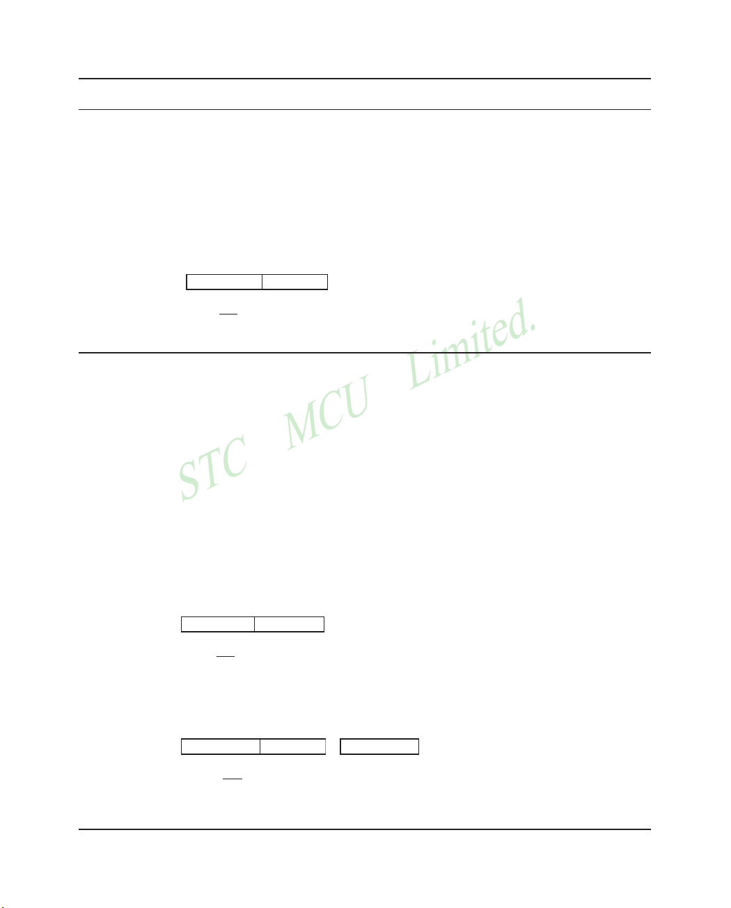
STC MCU Limited.
Mobile:(86)13922809991 Tel:086-755-82948412 Fax:86-755-82905966
STC MCU Limited. website:www.STCMCU.com
82
www.STCMCU.com
CPL A
Function: Complement Accumulator
Description: Each bit of the Accumulator is logically complemented (one’s complement). Bits which
previously contained a one are changed to a zero and vice-versa. No flags are affected.
Example: The Accumulator contains 5CH(01011100B). The instruction,
CPL A
will leave the Accumulator set to 0A3H (101000011B).
Bytes: 1
Cycles: 1
Encoding:
1 1 1 1 0 1 0 0
Operation: CPL
(A)
CPL bit
Function: Complement bit
Description: The bit variable specified is complemented. A bit which had been a one is changed to zero
and vice-versa. No other flags are affected. CLR can operate on the carry or any directly
addressable bit.
Note:When this instruction is used to modify an output pin, the value used as the original
data will be read from the output data latch, not the input pin.
Example: Port 1 has previously been written with 5DH (01011101B). The instruction,
CLR P1.1
CLR P1.2
will leave the port set to 59H (01011001B).
CPL C
Bytes: 1
Cycles: 1
Encoding:
1 0 1 1 0 0 1 1
Operation: CPL
(C)
CPL bit
Bytes: 2
Cycles: 1
Encoding:
1 0 1 1 0 0 1 0 bit address
Operation: CPL
(bit)
Page 83

STC MCU Limited.
Mobile:(86)13922809991 Tel:86-755-82948412 Fax:86-755-82905966
STC MCU Limited.
website:www.STCMCU.com
83
www.STCMCU.com
DA A
Function: Decimal-adjust Accumulator for Addition
Description: DA A adjusts the eight-bit value in the Accumulator resulting from the earlier addition of
two variables (each in packed-BCD format), producing two four-bit digits.Any ADD or
ADDC instruction may have been used to perform the addition.
If Accumulator bits 3-0 are greater than nine (xxxx1010-xxxx1111), or if the AC flag is one,
six is added to the Accumulator producing the proper BCD digit in the low-order nibble.
This internal addition would set the carry flag if a carry-out of the low-order four-bit field
propagated through all high-order bits, but it would not clear the carry flag otherwise.
If the carry flag is now set or if the four high-order bits now exceed nine(1010xxxx111xxxx), these high-order bits are incremented by six, producing the proper BCD digit
in the high-order nibble. Again, this would set the carry flag if there was a carry-out of the
high-order bits, but wouldn’t clear the carry. The carry flag thus indicates if the sum of
the original two BCD variables is greater than 100, allowing multiple precision decimal
addition. OV is not affected.
All of this occurs during the one instruction cycle. Essentially, this instruction performs the
decimal conversion by adding 00H, 06H, 60H, or 66H to the Accumulator, depending on
initial Accumulator and PSW conditions.
Note: DA A cannot simply convert a hexadecimal number in the Accumulator to BCD
notation, nor does DA A apply to decimal subtraction.
Example: The Accumulator holds the value 56H(01010110B) representing the packed BCD digits of
the decimal number 56. Register 3 contains the value 67H (01100111B) representing the
packed BCD digits of the decimal number 67.The carry flag is set. The instruction sequence.
ADDC A,R3
DA A
will first perform a standard twos-complement binary addition, resulting in the value 0BEH
(10111110) in the Accumulator. The carry and auxiliary carry flags will be cleared.
The Decimal Adjust instruction will then alter the Accumulator to the value 24H
(00100100B), indicating the packed BCD digits of the decimal number 24, the low-order
two digits of the decimal sum of 56,67, and the carry-in. The carry flag will be set by the
Decimal Adjust instruction, indicating that a decimal overflow occurred. The true sum 56,
67, and 1 is 124.
BCD variables can be incremented or decremented by adding 01H or 99H. If the Accumulator initially holds 30H (representing the digits of 30 decimal), then the instruction sequence,
ADD A,#99H
DA A
will leave the carry set and 29H in the Accumulator, since 30+99=129. The low-order byte
of the sum can be interpreted to mean 30 – 1 = 29.
Page 84

STC MCU Limited.
Mobile:(86)13922809991 Tel:086-755-82948412 Fax:86-755-82905966
STC MCU Limited. website:www.STCMCU.com
84
www.STCMCU.com
Bytes: 1
Cycles: 1
Encoding:
1 1 0 1 0 1 0 0
Operation: DA
-contents of Accumulator are BCD
IF [[(A
3-0
) > 9] V [(AC) = 1]]
THEN(A
3-0
(A
3-0
) + 6
AND
IF [[(A
7-4
) > 9] V [(C) = 1]]
THEN (A
7-4
(A
7-4
) + 6
DEC byte
Function: Decrement
Description: The variable indicated is decremented by 1. An original value of 00H will underflow to
0FFH.
No flags are affected. Four operand addressing modes are allowed: accumulator, register,
direct, or register-indirect.
Note: When this instruction is used to modify an output port, the value used as the original
port data will be read from the output data latch, not the input pins.
Example: Register 0 contains 7FH (01111111B). Internal RAM locations 7EH and 7FH contain 00H
and 40H, respectively. The instruction sequence,
DEC @R0
DEC R0
DEC @R0
will leave register 0 set to 7EH and internal RAM locations 7EH and 7FH set to 0FFH and
3FH.
DEC A
Bytes: 1
Cycles: 1
Encoding:
0 0 0 1 0 1 0 0
Operation: DEC
(A) -1
DEC Rn
Bytes: 1
Cycles: 1
Encoding:
0 0 0 1 1 r r r
Operation: DEC
(Rn) - 1
Page 85

STC MCU Limited.
Mobile:(86)13922809991 Tel:86-755-82948412 Fax:86-755-82905966
STC MCU Limited.
website:www.STCMCU.com
85
www.STCMCU.com
DEC direct
Bytes: 2
Cycles: 1
Encoding:
0 0 0 1 0 1 0 1 direct address
Operation: DEC
(direct) -1
DEC @Ri
Bytes: 1
Cycles: 1
Encoding:
0 0 0 1 0 1 1 i
Operation: DEC
((Ri)) - 1
DIV AB
Function: Divide
Description: DIV AB divides the unsigned eight-bit integer in the Accumulator by the unsigned eight-bit
integer in register B. The Accumulator receives the integer part of the quotient; register B
receives the integer remainder. The carry and OV flags will be cleared.
Exception: if B had originally contained 00H, the values returned in the Accumulator and
B-register will be undefined and the overflow flag will be set. The carry flag is cleared in any
case.
Example: The Accumulator contains 251(OFBH or 11111011B) and B contains 18(12H or 00010010B).
The instruction,
DIV AB
will leave 13 in the Accumulator (0DH or 00001101B) and the value 17 (11H or 00010010B)
in B, since 251 = (13×18) + 17. Carry and OV will both be cleared.
Bytes: 1
Cycles: 4
Encoding:
1 0 0 0 0 1 0 0
Operation: DIV
(A)
15-8
(B)
7-0
(A)/(B)
Page 86

STC MCU Limited.
Mobile:(86)13922809991 Tel:086-755-82948412 Fax:86-755-82905966
STC MCU Limited. website:www.STCMCU.com
86
www.STCMCU.com
DJNZ <byte>, <rel-addr>
Function: Decrement and Jump if Not Zero
Description: DJNZ decrements the location indicated by 1, and branches to the address indicated by the
second operand if the resulting value is not zero. An original value of 00H will underflow to
0FFH. No flags are afected. The branch destination would be computed by adding the signed
relative-displacement value in the last instruction byte to the PC, after incrementing the PC
to the first byte of the following instruction.
The location decremented may be a register or directly addressed byte.
Note: When this instruction is used to modify an output port, the value used as the original
port data will be read from the output data latch, not the input pins.
Example: Internal RAM locations 40H, 50H, and 60H contain the values 01H, 70H, and 15H,
respectively. The instruction sequence,
DJNZ 40H, LABEL_1
DJNZ 50H, LABEL_2
DJNZ 60H, LABEL_3
will cause a jump to the instruction at label LABEL_2 with the values 00H, 6FH, and 15H in
the three RAM locations. The first jump was not taken because the result was zero.
This instruction provides a simple way of executing a program loop a given number of times,
or for adding a moderate time delay (from 2 to 512 machine cycles) with a single instruction
The instruction sequence,
MOV R2,#8
TOOOLE: CPL P1.7
DJNZ R2, TOOGLE
will toggle P1.7 eight times, causing four output pulses to appear at bit 7 of output Port 1.
Each pulse will last three machine cycles; two for DJNZ and one to alter the pin.
DJNZ Rn,rel
Bytes: 2
Cycles: 2
Encoding:
1 1 0 1 1 r r r rel. address
Operation: DJNZ
(PC) + 2
(Rn) – 1
IF (Rn) > 0 or (Rn) < 0
THEN
(PC)+ rel
DJNZ direct, rel
Bytes: 3
Cycles: 2
Encoding:
1 1 0 1 0 1 0 1 direct address rel. address
Page 87
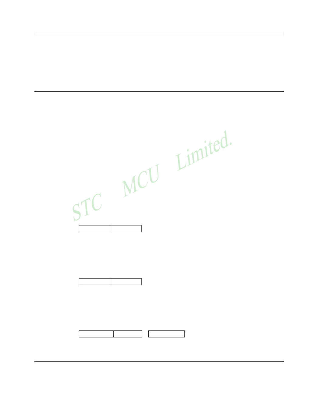
STC MCU Limited.
Mobile:(86)13922809991 Tel:86-755-82948412 Fax:86-755-82905966
STC MCU Limited.
website:www.STCMCU.com
87
www.STCMCU.com
Operation: DJNZ
(PC) + 2
(direct) – 1
IF (direct) > 0 or (direct) < 0
THEN
(PC) + rel
INC <byte>
Function: Increment
Description: INC increments the indicated variable by 1. An original value of 0FFH will overflow to
00H.No flags are affected. Three addressing modes are allowed: register, direct, or registerindirect.
Note: When this instruction is used to modify an output port, the value used as the original
port data will be read from the output data latch, not the input pins.
Example: Register 0 contains 7EH (011111110B). Internal RAM locations 7EH and 7FH contain 0FFH
and 40H, respectively. The instruction sequence,
INC @R0
INC R0
INC @R0
will leave register 0 set to 7FH and internal RAM locations 7EH and 7FH holding
(respectively) 00H and 41H.
INC A
Bytes: 1
Cycles: 1
Encoding:
0 0 0 0 0 1 0 0
Operation: INC
INC Rn
Bytes: 1
Cycles: 1
Encoding:
0 0 0 0 1 r r r
Operation: INC
INC direct
Bytes: 2
Cycles: 1
Encoding:
0 0 0 0 0 1 0 1 direct address
Operation: INC
(direct) + 1
Page 88

STC MCU Limited.
Mobile:(86)13922809991 Tel:086-755-82948412 Fax:86-755-82905966
STC MCU Limited. website:www.STCMCU.com
88
www.STCMCU.com
INC @Ri
Bytes: 1
Cycles: 1
Encoding:
0 0 0 0 0 1 1 i
Operation: INC
((Ri)) + 1
INC DPTR
Function: Increment Data Pointer
Description: Increment the 16-bit data pointer by 1. A 16-bit increment (modulo 216) is performed; an
overflow of the low-order byte of the data pointer (DPL) from 0FFH to 00H will increment
the high-order-byte (DPH). No flags are affected.
This is the only 16-bit register which can be incremented.
Example: Register DPH and DPL contains 12H and 0FEH,respectively. The instruction sequence,
INC DPTR
INC DPTR
INC DPTR
will change DPH and DPL to 13H and 01H.
Bytes: 1
Cycles: 2
Encoding:
1 0 1 0 0 0 1 1
Operation: INC
JB bit, rel
Function: Jump if Bit set
Description: If the indicated bit is a one, jump to the address indicated; otherwise proceed with the next
instruction. The branch destination is computed by adding the signed relative-displacement
in the third instruction byte to the PC, after incrementing the PC to the first byte of the next
instruction. The bit tested is not modified. No flags are affected.
Example: The data present at input port 1 is 11001010B. The Accumulator holds 56 (01010110B). The
instruction sequence,
JB P1.2, LABEL1
JB ACC.2, LABEL2
will cause program execution to branch to the instruction at label LABEL2.
Bytes: 3
Cycles: 2
Encoding:
0 0 1 0 0 0 0 0 bit address rel. address
Operation: JB
(PC)+ 3
IF (bit) = 1
THEN
(PC) + rel
Page 89

STC MCU Limited.
Mobile:(86)13922809991 Tel:86-755-82948412 Fax:86-755-82905966
STC MCU Limited.
website:www.STCMCU.com
89
www.STCMCU.com
JBC bit, rel
Function: Jump if Bit is set and Clear bit
Description: If the indicated bit is one,branch to the address indicated;otherwise proceed with the next
instruction.The bit wili not be cleared if it is already a zero. The branch destination is
computed by adding the signed relative-displacement in the third instruction byte to the PC,
after incrementing the PC to the first byte of the next instruction. No flags are affected.
Note: When this instruction is used to test an output pin, the value used as the original data
will be read from the output data latch, not the input pin.
Example: The Accumulator holds 56H (01010110B). The instruction sequence,
JBC ACC.3, LABEL1
JBC ACC.2, LABEL2
will cause program execution to continue at the instruction identified by the label LABEL2,
with the Accumulator modified to 52H (01010010B).
Bytes: 3
Cycles: 2
Encoding:
0 0 0 1 0 0 0 0 bit address rel. address
Operation: JBC
(PC)+ 3
IF (bit) = 1
THEN
(PC) + rel
JC rel
Function: Jump if Carry is set
Description: If the carry flag is set, branch to the address indicated; otherwise proceed with the next
instruction. The branch destination is computed by adding the signed relative-displacement in
the second instruction byte to the PC, after incrementing the PC twice.No flags are affected.
Example: The carry flag is cleared. The instruction sequence,
JC LABEL1
CPL C
JC LABEL2s
will set the carry and cause program execution to continue at the instruction identified by the
label LABEL2.
Bytes: 2
Cycles: 2
Encoding:
0 1 0 0 0 0 0 0 rel. address
Operation: JC
(PC)+ 2
IF (C) = 1
THEN
(PC) + rel
Page 90

STC MCU Limited.
Mobile:(86)13922809991 Tel:086-755-82948412 Fax:86-755-82905966
STC MCU Limited. website:www.STCMCU.com
90
www.STCMCU.com
JMP @A+DPTR
Function: Jump indirect
Description: Add the eight-bit unsigned contents of the Accumulator with the sixteen-bit data pointer,
and load the resulting sum to the program counter. This will be the address for subsequent
instruction fetches. Sixteen-bit addition is performed (modulo 216): a carry-out from the loworder eight bits propagates through the higher-order bits. Neither the Accumulator nor the
Data Pointer is altered. No flags are affected.
Example: An even number from 0 to 6 is in the Accumulator. The following sequence of instructions
will branch to one of four AJMP instructions in a jump table starting at JMP_TBL:
MOV DPTR, #JMP_TBL
JMP @A+DPTR
JMP-TBL: AJMP LABEL0
AJMP LABEL1
AJMP LABEL2
AJMP LABEL3
If the Accumulator equals 04H when starting this sequence, execution will jump to label
LABEL2. Remember that AJMP is a two-byte instruction, so the jump instructions start at
every other address.
Bytes: 1
Cycles: 2
Encoding:
0 1 1 1 0 0 1 1
Operation: JMP
(A) + (DPTR)
JNB bit, rel
Function: Jump if Bit is not set
Description: If the indicated bit is a zero, branch to the indicated address; otherwise proceed with the next
instruction. The branch destination is computed by adding the signed relative-displacement
in the third instruction byte to the PC, after incrementing the PC to the first byte of the next
instruction. The bit tested is not modified. No flags are affected.
Example: The data present at input port 1 is 11001010B. The Accumulator holds 56H (01010110B).
The instruction sequence,
JNB P1.3, LABEL1
JNB ACC.3, LABEL2
will cause program execution to continue at the instruction at label LABEL2
Bytes: 3
Cycles: 2
Encoding:
0 0 1 1 0 0 0 0 bit address rel. address
Operation: JNB
(PC)+ 3
IF (bit) = 0
(PC) + rel
Page 91

STC MCU Limited.
Mobile:(86)13922809991 Tel:86-755-82948412 Fax:86-755-82905966
STC MCU Limited.
website:www.STCMCU.com
91
www.STCMCU.com
JNC rel
Function: Jump if Carry not set
Description: If the carry flag is a zero, branch to the address indicated; otherwise proceed with the next
instruction. The branch destination is computed by adding the signed relative-displacement
in the second instruction byte to the PC, after incrementing the PC twice to point to the next
instruction. The carry flag is not modified
Example: The carry flag is set. The instruction sequence,
JNC LABEL1
CPL C
JNC LABEL2
will clear the carry and cause program execution to continue at the instruction identified by
the label LABEL2.
Bytes: 2
Cycles: 2
Encoding:
0 1 0 1 0 0 0 0 rel. address
Operation: JNC
(PC)+ 2
IF (C) = 0
(PC) + rel
JNZ rel
Function: Jump if Accumulator Not Zero
Description: If any bit of the Accumulator is a one, branch to the indicated address; otherwise proceed
with the next instruction. The branch destination is computed by adding the signed relativedisplacement in the second instruction byte to the PC, after incrementing the PC twice. The
Accumulator is not modified. No flags are affected.
Example: The Accumulator originally holds 00H. The instruction sequence,
JNZ LABEL1
INC A
JNZ LAEEL2
will set the Accumulator to 01H and continue at label LABEL2.
Bytes: 2
Cycles: 2
Encoding:
0 1 1 1 0 0 0 0 rel. address
Operation: JNZ
(PC)+ 2
(PC) + rel
Page 92

STC MCU Limited.
Mobile:(86)13922809991 Tel:086-755-82948412 Fax:86-755-82905966
STC MCU Limited. website:www.STCMCU.com
92
www.STCMCU.com
JZ rel
Function: Jump if Accumulator Zero
Description: If all bits of the Accumulator are zero, branch to the address indicated; otherwise proceed
with the next instruction. The branch destination is computed by adding the signed relativedisplacement in the second instruction byte to the PC, after incrementing the PC twice. The
Accumulator is not modified. No flags are affected.
Example: The Accumulator originally contains 01H. The instruction sequence,
JZ LABEL1
DEC A
JZ LAEEL2
will change the Accumulator to 00H and cause program execution to continue at the
instruction identified by the label LABEL2.
Bytes: 2
Cycles: 2
Encoding:
0 1 1 0 0 0 0 0 rel. address
Operation: JZ
(PC)+ 2
IF (A) = 0
(PC) + rel
LCALL addr16
Function: Long call
Description: LCALL calls a subroutine loated at the indicated address. The instruction adds three to the
program counter to generate the address of the next instruction and then pushes the 16-bit
result onto the stack (low byte first), incrementing the Stack Pointer by two. The high-order
and low-order bytes of the PC are then loaded, respectively, with the second and third bytes
of the LCALL instruction. Program execution continues with the instruction at this address.
The subroutine may therefore begin anywhere in the full 64K-byte program memory address
space. No flags are affected.
Example: Initially the Stack Pointer equals 07H. The label “SUBRTN” is assigned to program memory
location 1234H. After executing the instruction,
LCALL SUBRTN
at location 0123H, the Stack Pointer will contain 09H, internal RAM locations 08H and 09H
will contain 26H and 01H, and the PC will contain 1234H.
Bytes: 3
Cycles: 2
Encoding:
0 0 0 1 0 0 1 0 addr15-addr8 addr7-addr0
Operation: LCALL
(PC) + 3
(SP) + 1
(PC
7-0
)
(SP) + 1
(PC
15-8
)
addr
15-0
Page 93

STC MCU Limited.
Mobile:(86)13922809991 Tel:86-755-82948412 Fax:86-755-82905966
STC MCU Limited.
website:www.STCMCU.com
93
www.STCMCU.com
LJMP addr16
Function: Long Jump
Description: LJMP causes an unconditional branch to the indicated address, by loading the high-order
and low-order bytes of the PC (respectively) with the second and third instruction bytes. The
destination may therefore be anywhere in the full 64K program memory address space. No
flags are affected.
Example: The label “JMPADR” is assigned to the instruction at program memory location 1234H. The
instruction,
LJMP JMPADR
at location 0123H will load the program counter with 1234H.
Bytes: 3
Cycles: 2
Encoding:
0 0 0 0 0 0 1 0 addr15-addr8 addr7-addr0
Operation: LJMP
addr
15-0
MOV <dest-byte> , <src-byte>
Function: Move byte variable
Description: The byte variable indicated by the second operand is copied into the location specified by the
first operand. The source byte is not affected. No other register or flag is affected.
This is by far the most flexible operation. Fifteen combinations of source and destination
addressing modes are allowed.
Example: Internal RAM location 30H holds 40H. The value of RAM location 40H is 10H. The data
present at input port 1 is 11001010B (0CAH).
MOV R0, #30H ;R0< = 30H
MOV A, @R0 ;A < = 40H
MOV R1, A ;R1 < = 40H
MOV B, @Rl ;B < = 10H
MOV @Rl, Pl ;RAM (40H) < = 0CAH
MOV P2, P1 ;P2 #0CAH
leaves the value 30H in register 0,40H in both the Accumulator and register 1,10H in register
B, and 0CAH(11001010B) both in RAM location 40H and output on port 2.
MOV A,Rn
Bytes: 1
Cycles: 1
Encoding:
1 1 1 0 1 r r r
Operation: MOV
(Rn)
Page 94

STC MCU Limited.
Mobile:(86)13922809991 Tel:086-755-82948412 Fax:86-755-82905966
STC MCU Limited. website:www.STCMCU.com
94
www.STCMCU.com
*MOV A,direct
Bytes: 2
Cycles: 1
Encoding:
1 1 1 0 0 1 0 1 direct address
Operation: MOV
(direct)
*MOV A, ACC is not a valid instruction
MOV A,@Ri
Bytes: 1
Cycles: 1
Encoding:
1 1 1 0 0 1 1 i
Operation: MOV
((Ri))
MOV A,#data
Bytes: 2
Cycles: 1
Encoding:
0 1 1 1 0 1 0 0 immediate data
Operation: MOV
#data
MOV Rn, A
Bytes: 1
Cycles: 1
Encoding:
1 1 1 1 1 r r r
Operation: MOV
(A)
MOV Rn,direct
Bytes: 2
Cycles: 2
Encoding:
1 0 1 0 1 r r r direct addr.
Operation: MOV
(direct)
MOV Rn,#data
Bytes: 2
Cycles: 1
Encoding:
0 1 1 1 1 r r r immediate data
Operation: MOV
#data
Page 95

STC MCU Limited.
Mobile:(86)13922809991 Tel:86-755-82948412 Fax:86-755-82905966
STC MCU Limited.
website:www.STCMCU.com
95
www.STCMCU.com
MOV direct, A
Bytes: 2
Cycles: 1
Encoding:
1 1 1 1 0 1 0 1 direct address
Operation: MOV
(A)
MOV direct, Rn
Bytes: 2
Cycles: 2
Encoding:
1 0 0 0 1 r r r direct address
Operation: MOV
(Rn)
MOV direct, direct
Bytes: 3
Cycles: 2
Encoding:
1 0 0 0 0 1 0 1 dir.addr. (src)
Operation: MOV
(direct)
MOV direct, @Ri
Bytes: 2
Cycles: 2
Encoding:
1 0 0 0 0 1 1 i direct addr.
Operation: MOV
((Ri))
MOV direct,#data
Bytes: 3
Cycles: 2
Encoding:
0 1 1 1 0 1 0 1 direct address
Operation: MOV
#data
MOV @Ri, A
Bytes: 1
Cycles: 1
Encoding:
1 1 1 1 0 1 1 i
Operation: MOV
(A)
Page 96

STC MCU Limited.
Mobile:(86)13922809991 Tel:086-755-82948412 Fax:86-755-82905966
STC MCU Limited. website:www.STCMCU.com
96
www.STCMCU.com
MOV @Ri, direct
Bytes: 2
Cycles: 2
Encoding:
1 0 1 0 0 1 1 i direct addr.
Operation: MOV
(direct)
MOV @Ri, #data
Bytes: 2
Cycles: 1
Encoding:
0 1 1 1 0 1 1 i immediate data
Operation: MOV
#data
MOV <dest-bit> , <src-bit>
Function: Move bit data
Description: The Boolean variable indicated by the second operand is copied into the location specified by
the first operand. One of the operands must be the carry flag; the other may be any directly
addressable bit. No other register or flag is affected.
Example: The carry flag is originally set. The data present at input Port 3 is 11000101B. The data
previously written to output Port 1 is 35H (00110101B).
MOV P1.3, C
MOV C, P3.3
MOV P1.2, C
will leave the carry cleared and change Port 1 to 39H (00111001B).
MOV C,bit
Bytes: 2
Cycles: 1
Encoding:
1 0 1 0 0 0 1 1 bit address
Operation: MOV
(bit)
MOV bit,C
Bytes: 2
Cycles: 2
Encoding:
1 0 0 1 0 0 1 0 bit address
Operation: MOV
(C)
Page 97

STC MCU Limited.
Mobile:(86)13922809991 Tel:86-755-82948412 Fax:86-755-82905966
STC MCU Limited.
website:www.STCMCU.com
97
www.STCMCU.com
MOV DPTR , #data 16
Function: Load Data Pointer with a 16-bit constant
Description: The Data Pointer is loaded with the 16-bit constant indicated.The 16-bit constant is loaded
into the second and third bytes of the instruction. The second byte (DPH) is the high-order
byte, while the third byte (DPL) holds the low-order byte. No flags are affected.
This is the only instruction which moves 16 bits of data at once.
Example: The instruction,
MOV DPTR, #1234H
will load the value 1234H into the Data Pointer: DPH will hold 12H and DPL will hold 34H.
Bytes: 3
Cycles: 2
Encoding:
1 0 0 1 0 0 0 0 immediate data 15-8
Operation: MOV
#data
15-0
15-8
#data
7-0
MOVC A , @A+ <base-reg>
Function: Move Code byte
Description: The MOVC instructions load the Accumulator with a code byte, or constant from program
memory. The address of the byte fetched is the sum of the original unsigned eight-bit.
Accumulator contents and the contents of a sixteen-bit base register, which may be either
the Data Pointer or the PC. In the latter case, the PC is incremented to the address of the
following instruction before being added with the Accumulator; otherwise the base register
is not altered. Sixteen-bit addition is performed so a carry-out from the low-order eight bits
may propagate through higher-order bits. No flags are affected.
Example: A value between 0 and 3 is in the Accumulator. The following instructions will translate the
value in the Accumulator to one of four values defimed by the DB (define byte) directive.
REL-PC: INC A
MOVC A, @A+PC
RET
DB 66H
DB 77H
DB 88H
DB 99H
If the subroutine is called with the Accumulator equal to 01H, it will return with 77H in the
Accumulator. The INC A before the MOVC instruction is needed to “get around” the RET
instruction above the table. If several bytes of code separated the MOVC from the table, the
corresponding number would be added to the Accumulator instead.
MOVC A,@A+DPTR
Bytes: 1
Cycles: 2
Encoding:
1 0 0 1 0 0 1 1
Operation: MOVC
((A)+(DPTR))
Page 98

STC MCU Limited.
Mobile:(86)13922809991 Tel:086-755-82948412 Fax:86-755-82905966
STC MCU Limited. website:www.STCMCU.com
98
www.STCMCU.com
MOVC A,@A+PC
Bytes: 1
Cycles: 2
Encoding:
1 0 0 0 0 0 1 1
Operation: MOVC
((A)+(PC))
MOVX <dest-byte> , <src-byte>
Function: Move External
Description: The MOVX instructions transfer data between the Accumulator and a byte of external data
memory, hence the “X” appended to MOV. There are two types of instructions, differing in
whether they provide an eight-bit or sixteen-bit indirect address to the external data RAM.
In the first type, the contents of R0 or R1 in the current register bank provide an eight-bit
address multiplexed with data on P0. Eight bits are sufficient for external I/O expansion
decoding or for a relatively small RAM array. For somewhat larger arrays, any output port
pins can be used to output higher-order address bits. These pins would be controlled by an
output instruction preceding the MOVX.
In the second type of MOVX instruction, the Data Pointer generates a sixteen-bit address.
P2 outputs the high-order eight address bits (the contents of DPH) while P0 multiplexes the
low-order eight bits (DPL) with data. The P2 Special Function Register retains its previous
contents while the P2 output buffers are emitting the contents of DPH. This form is faster and
more efficient when accessing very large data arrays (up to 64K bytes), since no additional
instructions are needed to set up the output ports.
It is possible in some situations to mix the two MOVX types. A large RAM array with its
high-order address lines driven by P2 can be addressed via the Data Pointer, or with code to
output high-order address bits to P2 followed by a MOVX instruction using R0 or R1.
Example: An external 256 byte RAM using multiplexed address/data lines (e.g., an Intel 8155 RAM/
I/O/Timer) is connected to the 8051 Port 0. Port 3 provides control lines for the external
RAM. Ports 1 and 2 are used for normal I/O. Registers 0 and 1 contain 12H and 34H.
Location 34H of the external RAM holds the value 56H. The instruction sequence,
MOVX A, @R1
MOVX @R0, A
copies the value 56H into both the Accumulator and external RAM location 12H.
MOVX A,@Ri
Bytes: 1
Cycles: 2
Encoding:
1 1 1 0 0 0 1 i
Operation: MOVX
((Ri))
Page 99

STC MCU Limited.
Mobile:(86)13922809991 Tel:86-755-82948412 Fax:86-755-82905966
STC MCU Limited.
website:www.STCMCU.com
99
www.STCMCU.com
MOVX A,@DPTR
Bytes: 1
Cycles: 2
Encoding:
1 1 1 0 0 0 0 0
Operation: MOVX
((DPTR))
MOVX @Ri, A
Bytes: 1
Cycles: 2
Encoding:
1 1 1 1 0 0 1 i
Operation: MOVX
(A)
MOVX @DPTR, A
Bytes: 1
Cycles: 2
Encoding:
1 1 1 1 0 0 0 0
Operation: MOVX
(A)
MUL AB
Function: Multiply
Description: MUL AB multiplies the unsigned eight-bit integers in the Accumulator and register B. The
low-order byte of the sixteen-bit product is left in the Accumulator, and the high-order byte
in B. If the product is greater than 255 (0FFH) the overflow flag is set; otherwise it is cleared.
The carry flag is always cleared
Example: Originally the Accumulator holds the value 80 (50H). Register B holds the value 160
(0A0H). The instruction,
MUL AB
will give the product 12,800 (3200H), so B is changed to 32H (00110010B) and the
Accumulator is cleared. The overflow flag is set, carry is cleared.
Bytes: 1
Cycles: 4
Encoding:
1 0 1 0 0 1 0 0
Operation: MUL
(A)
7-0
(A)×(B)
(B)
15-8
Page 100

STC MCU Limited.
Mobile:(86)13922809991 Tel:086-755-82948412 Fax:86-755-82905966
STC MCU Limited. website:www.STCMCU.com
100
www.STCMCU.com
NOP
Function: No Operation
Description: Execution continues at the following instruction. Other than the PC, no registers or flags are
affected.
Example: It is desired to produce a low-going output pulse on bit 7 of Port 2 lasting exactly 5 cycles. A
simple SETB/CLR sequence would generate a one-cycle pulse, so four additional cycles
must be inserted. This may be done (assuming no interrupts are enabled) with the instruction
sequence.
CLR P2.7
NOP
NOP
NOP
NOP
SETB P2.7
Bytes: 1
Cycles: 1
Encoding:
0 0 0 0 0 0 0 0
Operation: NOP
(PC) (PC)+1
ORL <dest-byte> , <src-byte>
Function: Logical-OR for byte variables
Description: ORL performs the bitwise logical-OR operation between the indicated variables, storing the
results in the destination byte. No flags are affected.
The two operands allow six addressing mode combinations. When the destination is the
Accumulator, the source can use register, direct, register-indirect, or immediate addressing;
when the destination is a direct address, the source can be the Accumulator or immediate
data.
Note: When this instruction is used to modify an output port, the value used as the original
port data will be read from the output data latch, not the input pins.
Example: If the Accumulator holds 0C3H (11000011B) and R0 holds 55H (01010101B) then the
instruction,
ORL A, R0
will leave the Accumulator holding the value 0D7H (11010111B).
When the destination is a directly addressed byte, the instruction can set combinations of bits
in any RAM location or hardware register. The pattern of bits to be set is determined by a
mask byte, which may be either a constant data value in the instruction or a variable
computed in the Accumulator at run-time.The instruction,
ORL P1, #00110010B
will set bits 5,4, and 1of output Port 1.
 Loading...