

Manual
Particle Monitor
LPM-II-plus

1
As a policy of continual improvement, STAUFF reserves the right to alter the specification without prior notice.
201.031 Date of Issue: 06 November 2018
EC Declaration of Conformity
The products included in this Declaration are all variants of the following:
With or without a moisture sensor
Compatible with mineral oil/ synthetic fluids, offshore fluids, phosphate esters (inc. aerospace
versions)
With or without a keypad/ display
With or without USB download
With relay outputs
With Modbus, CAN-bus and 4-20mA outputs
These are denoted by a combination of the following codes, and the serial numbers are preceded with
16:
LPM
II
O M O
D G W E
Product Manufacturer:
Walter Stauffenberg GmbH & Co. KG
Im Ehrenfeld 4
58791 Werdohl
Germany
The products described are in conformity with the following directives:
-2014/30/EU Electromagnetic Conformity
Certification Testing that has been carried out is in accordance with:
- DEF STAN 00-35 Part 3 issue 4 Environmental Test Methods
- BS EN 60068 range of standards covering environmental conditions
- BS EN 60529: 1992 + A2:2013 Degrees of Protection provided by enclosures (IP Code)
- BS EN 62262:2002 Degrees of Protection Provided for Electrical Equipment against External
Mechanical Impacts (IK Code)
- BS EN 60721-3-4: 1995 Part 3: Classification of Groups of Environmental Parameters and their
severities, Section 3.4

2
As a policy of continual improvement, STAUFF reserves the right to alter the specification without prior notice.
201.031 Date of Issue: 06 November 2018
Table of Contents
EC Declaration of Conformity ..................................................................................................................... 1
1 General Warnings and Information for the End User .............................................................................. 5
1.1 General Safety Warnings .................................................................................................................. 5
1.3 Operator Position and Dangerous Areas .......................................................................................... 6
1.4 Dangers and Hazards that cannot be eliminated .............................................................................. 7
1.5 Personal Protective Equipment ......................................................................................................... 7
2 Transportation and Storage ..................................................................................................................... 8
2.1 Transportation and Handling Conditions ........................................................................................... 8
2.2 Storage ............................................................................................................................................. 8
3 Warranty, Limitations and Disclaimers .................................................................................................... 9
4 Product Presentation ............................................................................................................................. 11
4.1 Benefits ........................................................................................................................................... 11
4.2 Product features .............................................................................................................................. 11
4.2.1 Moisture Sensor ....................................................................................................................... 11
4.2.2 Data Logger .............................................................................................................................. 12
5 Technical Specification .......................................................................................................................... 13
5.1 Performance ................................................................................................................................... 13
5.2 Electrical Interface .......................................................................................................................... 13
5.3 Physical Attributes .......................................................................................................................... 14
5.4 Fluid Characteristics ....................................................................................................................... 15
5.5 Environment .................................................................................................................................... 15
5.6 Wetted Parts List ............................................................................................................................. 15
6 Product Installation and General Operation .......................................................................................... 16
6.1 Installation ....................................................................................................................................... 16
6.1.1 Physical Procedure ............................................................................................................. 16
6.1.2 Electrical Interface .................................................................................................................... 17
6.1.3 Hydraulic Connection ............................................................................................................... 23
6.2 General Operation .......................................................................................................................... 26
6.2.1 Physical Checks ....................................................................................................................... 26
6.2.2 Front Panel Operation .............................................................................................................. 26

3
As a policy of continual improvement, STAUFF reserves the right to alter the specification without prior notice.
201.031 Date of Issue: 06 November 2018
6.2.3 LPM removal and Product Maintenance .................................................................................. 29
6.3 LPM Control .................................................................................................................................... 29
6.3.1 Computer Connection .............................................................................................................. 30
6.3.2 PC Software Operation ............................................................................................................ 31
6.3.3 Settings .................................................................................................................................... 32
6.4 Standard Communication Protocols ............................................................................................... 40
6.4.1 Modbus ..................................................................................................................................... 40
6.4.2 CAN-bus ................................................................................................................................... 44
6.4.3 Analogue 4-20mA Modes ......................................................................................................... 47
6.5 Disposal .......................................................................................................................................... 49
7 Troubleshooting / FAQ .......................................................................................................................... 50
7.1 Misuse of Product ........................................................................................................................... 50
7.2 Fault Finding ................................................................................................................................... 50
7.2.1 LED Flashing / Fault Codes ..................................................................................................... 50
7.2.2 Test Status ............................................................................................................................... 51
7.2.3 Other Faults .............................................................................................................................. 51
7.3 Test Duration .................................................................................................................................. 52
8 How to Order ......................................................................................................................................... 53
8.1 Common Features .......................................................................................................................... 53
9 Related Products ................................................................................................................................... 54
9.1 LPM Remote Display Unit ............................................................................................................... 54
9.2 LPMUSBInterface ........................................................................................................................... 54
9.3 LPM-DAV ........................................................................................................................................ 55
10 Service and Recalibration .................................................................................................................... 56
11 Reference ............................................................................................................................................ 57
11.1 Further Modbus Information .......................................................................................................... 57
11.1.1 Modbus Registers .................................................................................................................. 57
11.1.2 Implementing Modbus ............................................................................................................ 62
11.2 Further CAN-bus Information ........................................................................................................ 64
11.2.1 Example Walk through ........................................................................................................... 64
11.2.2 Messages ............................................................................................................................... 69
11.3 Measuring Water in Hydraulic and Lubricating Fluids ................................................................... 72
11.4 ISO4406:1999 Cleanliness Code System ..................................................................................... 73
11.5 NAS1638 Cleanliness Code System (now defunct, replaced by SAE AS4059E Table 1) ............ 74

4
As a policy of continual improvement, STAUFF reserves the right to alter the specification without prior notice.
201.031 Date of Issue: 06 November 2018
11.6 SAE AS4059 REV E Cleanliness Classification for Hydraulic fluids ............................................. 74
11.7 Recommendations ........................................................................................................................ 75
11.8 Hydraulic System Target Cleanliness Levels ................................................................................ 76
11.9 New ISO Medium Test Dust and its effect on ISO Contamination Control Standards .................. 77
11.10 Clean Working Practices ............................................................................................................. 81
5
As a policy of continual improvement, STAUFF reserves the right to alter the specification without prior notice.
201.031 Date of Issue: 06 November 2018
1 General Warnings and Information for the End User
1.1 General Safety Warnings
Do not operate, maintain or carry out any procedure before reading this manual. Any individual operating
the unit shall wear the following Personal Protective Equipment:
Protective eyewear
Safety shoes
Gloves
Overalls (or other suitable protective clothing)
Before carrying out any machine installation procedures and/or before use, one should scrupulously
follow the instructions listed in this manual. Moreover, it is necessary to comply with the current
regulations related to occupational accident prevention and safety in the workplace.
Notices aimed at the prevention of health hazards for personnel operating the machine are highlighted in
this document with signs having the following meaning:
WARNING
It relates to important information concerning the product, its use or part of this
documentation to which special attention must be paid
DANGER
It means that failure to comply with the relevant safety regulations may result in
death, serious injury or serious property damage.
In order to quickly identify the professionals concerned with reading this manual, the following definitions
were used:
OPERATOR
This is any individual whose task is to use the machine for production purposes.
The operator is aware of all the measures taken by the machine manufacturer in
order to eliminate any source of injury risk in the workplace and takes into
account the operational constraints.
PERSONNEL
INVOLVED IN
SLINGING AND
This is any individual whose task is to handle the machine or parts of it.
Personnel involved in slinging and hoisting operations are aware of the issues
regarding the safe transfer of machinery or parts of it and, therefore, uses
CAUTION
It means that failure to comply with the relevant safety regulations may result in
mild injury or property damage.
6
As a policy of continual improvement, STAUFF reserves the right to alter the specification without prior notice.
201.031 Date of Issue: 06 November 2018
HOISTING
OPERATIONS
appropriate lifting equipment, following the instructions provided by the product
manufacturer.
MACHINE
SETTER
This is any individual whose task is to set up the machine for its operation. The
machine setter is aware of the measures taken to eliminate all sources of injury
risks in the workplace and takes into account the operational constraints. The
machine setter takes all the appropriate precautions in order to operate in
utmost safety conditions.
MAINTENANCE
TECHNICIAN
This is any individual whose task is to carry out maintenance activities on the
machine. The maintenance technician is aware of the possible danger situations
that may arise and takes the appropriate precautions in order to eliminate the
risks of accidents in the workplace.
ELECTRICIAN
This is any individual whose task is to carry out maintenance activities on the
electrical wiring of the machine. The electrician is aware of the possible danger
situations that may arise and takes the appropriate precautions in order to
eliminate the risks of accidents in the workplace.
1.3 Operator Position and Dangerous Areas
No operator is required for operating the unit. However, the following areas are to be considered
dangerous: The ones close to the electric motor because of live equipment with potentially hot surfaces.
WARNING
The unit shall be taken out of service and/or dismantled in accordance with the
current regulations in force in the country where the machinery is installed
WARNING
The machinery is not suitable for outdoor use and all the electrical devices
have a protection class starting from IP 55 upwards.
7
As a policy of continual improvement, STAUFF reserves the right to alter the specification without prior notice.
201.031 Date of Issue: 06 November 2018
1.4 Dangers and Hazards that cannot be eliminated
-Electric shock risk on the electric motor; in case of motor malfunction
-Burn risk because of high temperatures
-Accidental oil leaks with consequent risk of slipping
-Hose breakage and resulting lubricant loss
With oil temperatures exceeding 40/45 °C, it is vital to be extremely careful when handling the metal
lances/the hoses and when moving the unit. Avoid direct contact with hot oil and with the filter body.
ALL EQUIPMENT SHOULD BE ALLOWED TO COOL PRIOR TO HANDLING, AFTER IT HAS
BEEN IN USE
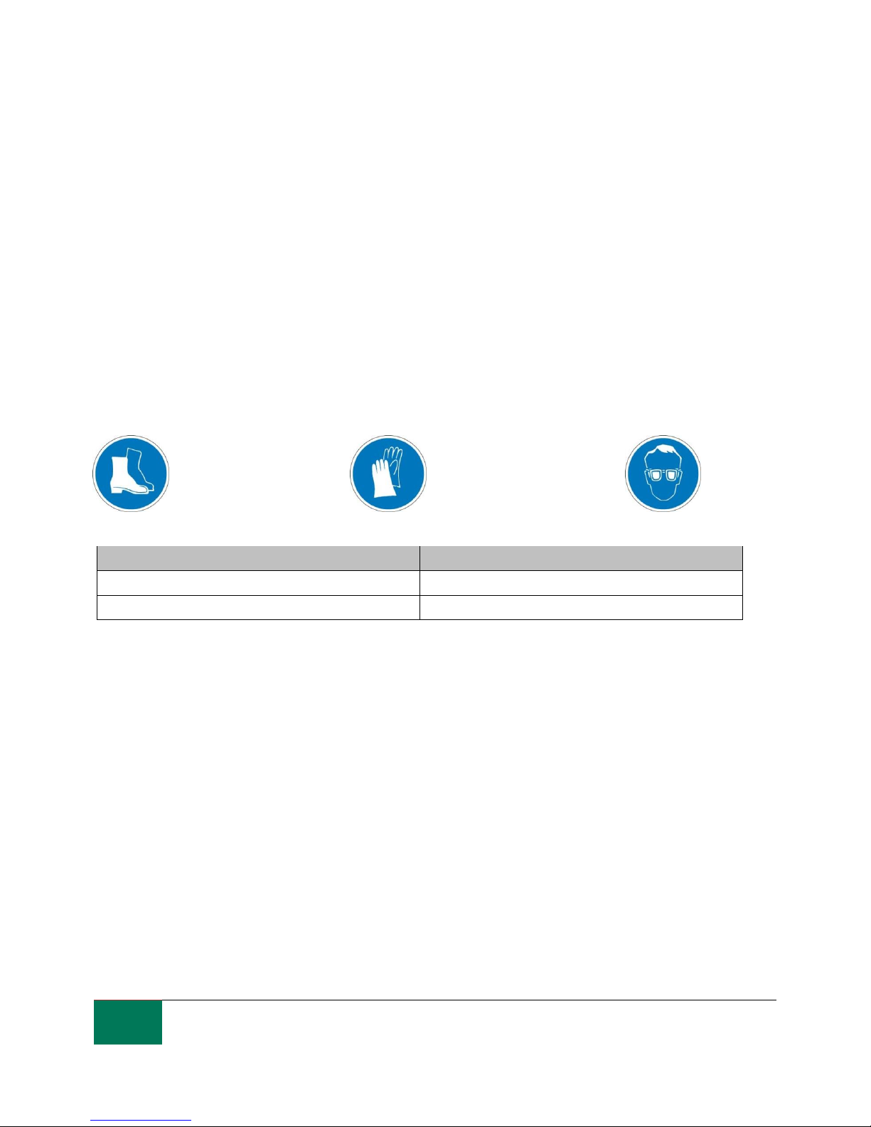
1.5 Personal Protective Equipment
When operating the unit, personnel must be wearing safety shoes, gloves and goggles. In general, the
PPEs to be used according to the activities on the machinery are listed in the following table:
Activity
PPEs
Ordinary operation
Shoes, gloves, goggles, overall
Planned maintenance
Shoes, gloves, goggles, overall

8
As a policy of continual improvement, STAUFF reserves the right to alter the specification without prior notice.
201.031 Date of Issue: 06 November 2018
2 Transportation and Storage
2.1 Transportation and Handling Conditions
The unit is shipped in a cardboard box, encased in polyurethane foam.
The packed weight of the LPM and accessories is 2.5kg.
2.2 Storage
The unit should be stored in a suitable location away from the production area when not in use. The unit
should be stored with the caps provided on the ports. This location should not impede any other
production or personnel.

9
As a policy of continual improvement, STAUFF reserves the right to alter the specification without prior notice.
201.031 Date of Issue: 06 November 2018
3 Warranty, Limitations and Disclaimers
Stauff warrant that the products that it manufactures and sells will be free from defects in material,
workmanship & performance for a period of 12 months from the date of shipment.
Hardware/Firmware
Should the hardware prove defective during the warranty period, Stauff, at its discretion, will either repair
the defective product or replace it with an equivalent product in exchange for the defective unit without
charge for parts, labour, carriage and insurance.
Software
Stauff warrants that software will operate substantially in accordance with its functional specification for 12
months from date of shipment provided that the integrity of the operating environment has not been
compromised through misuse, inappropriate handling, abnormal operating conditions, neglect or damage
(unintentional or otherwise) or the introduction of third party product (software or hardware) that in any way
conflicts with the Stauff product.
Eligibility
This warranty extends to the original purchaser only or to the end-user client of a Stauff authorised affiliate.
How to obtain service?
To obtain service under the terms of this warranty, the customer is required to notify Stauff before the
expiration of the warranty period and to return the item in accordance with Stauff product return policy.
Any product returned for warranty repair must be accompanied by a full fault report specifying the
symptoms and the conditions under which the fault occurs. Should Stauff incur additional cost as a result
of a failure to complete the appropriate paperwork, an administrative charge may be levied.
Exclusions
This warranty shall not apply to any defect, failure or damage caused by improper use or improper or
inadequate care. Stauff shall not be obligated to provide service under this warranty if:
a) Damage has been caused by a failure to make a full and proper inspection of the product (as described
by the documentation enclosed with the product at the time of shipment) on initial receipt of the product
following shipment;
b) Damage has been caused by the attempts of individuals, other than Stauff staff to repair or service the
product;
c) Damage has been caused by the improper use or a connection with incompatible equipment or product
including software applications.

10
As a policy of continual improvement, STAUFF reserves the right to alter the specification without prior notice.
201.031 Date of Issue: 06 November 2018
Charges
Under cover of this warranty, Stauff will pay the carriage and insurance charges for the shipment of
defective product back to site of manufacture and for its return to the client’s original site of despatch
except when:
a) Stauff product return policy has not been followed.
b) Product failure is caused by any of the exclusions described above, when the customer will be liable for
the full cost of the repair (parts and labour) plus all carriage and insurance costs to and from Stauff
premises.
c) The product is damaged in transit and a contributory cause is inadequate packaging. It is the customer’s
responsibility to ensure that the packaging used to return equipment to Stauff is the same, or has
equivalent protective qualities, to that used to ship the product to the customer in the first instance. Any
damage resulting from the use of inadequate packaging will nullify Stauff obligations under this
warranty. Should the customer’s product be damaged in transit following a repair at Stauff site, a full
photographic record of the damage must be obtained (packaging and the product) to support any claim
for recompense. Failure to present this evidence may limit Stauff obligations under this warranty.
THIS WARRANTY IS GIVEN BY STAUFF IN LIEU OF ANY OTHER WARRANTIES, EXPRESS OR
IMPLIED, INCLUDING BUT NOT LIMITED TO ANY IMPLIED WARRANTY OF MERCHANTABILITY,
NON INFRINGEMENT OR FITNESS FOR A PARTICULAR PURPOSE. STAUFF LTD SHALL NOT BE
LIABLE FOR ANY SPECIAL,
INDIRECT, INCIDENTAL OR CONSEQUENTIAL DAMAGES OR LOSSES ( INCLUDING LOSS OF
DATA), WE SPECIFICALLY DISCLAIM ANY AND ALL WARRANTIES TO CUSTOMERS OF THE
CUSTOMER. THE CUSTOMER’S SOLE REMEDY FOR ANY BREACH OF WARRANTY IS THE
REPAIR OR REPLACEMENT, AT STAUFF DISCRETION, OF THE FAILED PRODUCT.
Stauff maintains a policy of product improvement and reserves the right to modify the specifications without
prior notice.

11
As a policy of continual improvement, STAUFF reserves the right to alter the specification without prior notice.
201.031 Date of Issue: 06 November 2018
4 Product Presentation
The LPM measures and quantifies the numbers of solid contaminants in Hydraulic, Lubrication and
Transmission applications. The LPM-M is designed to be an accurate instrument for permanently
installed applications utilising mineral oil as the operating fluid. Other fluid media versions are available
for offshore [N] and aerospace phosphate ester [S] applications.
The unit can operate using any of the international standard formats ISO 4406:1999, NAS 1638, AS
4059E/F and ISO 11218.
The LPM incorporates a machine connector for power and PLC connection, capable of RS485, CANBUS
or 4-20mA signaling. A separate connector is also provided for simultaneous computer remote
monitoring or settings access using RS485 or a USB:RS485 interface.
The integrated data logger records up to 4000 test results internally, for use where a computer cannot be
permanently connected.
Simple switched inputs and alarm outputs are provided as alternative means of controlling the testing
and signaling the results. The “full colour” front panel led provides a basic indication of the cleanliness
level.
The instrument uses the light extinction principle whereby a specially collimated precision LED light
source shines through the fluid and lands on a photodiode. When a particle passes through the beam it
reduces the amount of light received by the diode, and from this change in condition, the size of the
particle can be deduced.
4.1 Benefits
Live real time monitoring
Manual, automatic and remote control flexibility
Moisture and temperature sensing
Multicolour LCD and LED for clear visual indication of any faults and alarms
Instant result download on USB versions
4.2 Product features
4.2.1 Moisture Sensor
LPM-W models measure water content using a capacitive RH (relative humidity) sensor. The result is
expressed as percentage saturation. 100% RH corresponds to the point at which free water exists in the
fluid, i.e. the fluid is no longer able to hold the water in a dissolved solution. This is also normally the
point at which damage occurs in a hydraulic system, so is an ideal measurement scale that is
independent of the fluid characteristics.
The water saturation point (100% RH) is temperature dependent, so the temperature is measured at the
same time. This enables results to be compared meaningfully.
The temperature measured is that of the fluid passing through the unit. Note this may differ from that of
the hydraulic system, depending on flow rate, pipe length and ambient temperature. It is not intended to
be an accurate indication of system temperature, but to provide a reference for the RH measurement.
Nevertheless experience has shown the temperature measured is within a few degrees of that of the
hydraulic system, in most applications.

12
As a policy of continual improvement, STAUFF reserves the right to alter the specification without prior notice.
201.031 Date of Issue: 06 November 2018
4.2.2 Data Logger
The LPM includes a built-in data logger, which adds the facility to log and timestamp test results locally
within an internal memory, even when not connected to a computer.
Test logging is determined by the log settings (see section 6.3.3).
Each log entry is time-stamped and contains the LPM serial number, so that it can be identified
later.
The LPM memory has space for around 4000 log entries. When full, the oldest log entry is
overwritten.
See section 6.3.1 + 6.3.2 for details of how to download the test log via bespoke windows based
software.
4.2.2.1 Data Transfer via USB Stick
The U version of the LPM allows direct download via a USB memory stick. With the LPM powered up,
plug the USB stick into the USB connector at the top of the unit.
The screen / indicator will turn yellow briefly as it writes the test records to the USB stick. When
complete, it will turn green and the stick can be removed. If there is a problem with the data transfer
(stick full or corrupt or not recognised) then the screen / indicator will turn red. If this happens the
operator can remove the stick and try again with an alternative.
The USB stick provided with the unit is pre-formatted for the transfer. Other USB sticks may need to be
re-formatted (FAT32).
PLEASE NOTE: The USB option is not to be used for anything other than a
memory stick for results download. Any subsequent use other than that
intended may cause damage to the device

13
As a policy of continual improvement, STAUFF reserves the right to alter the specification without prior notice.
201.031 Date of Issue: 06 November 2018
5 Technical Specification
5.1 Performance
Technology LED Based Light Extinction Automatic Optical Contamination Monitor
Particle Sizing >4, 6, 14, 21, 25, 38, 50, 70μm
Analysis range ISO 4406: Code 0 to 25
NAS 1638 Class 00 to 12
AS4059 Rev E Table 1 & 2 Sizes A-F: 000
Please Note: (Lower Limits are Test Time dependent)
If system cleanliness is expected to be above 22/21/18 or approx. NAS 12
Calibration Each unit individually calibrated with ISO Medium Test Dust (MTD) based on
ISO 11171, on equipment certified by I.F.T.S. ISO 11943
Moisture & Temperature Measurement % saturation (RH) and fluid temperature (°C) – Mineral Oil /
Diesel version only
Accuracy ±½ ISO code for 4, 6, 14μm
±1 code for 21, 25, 38, 50, 70μm
±3°C
±3%RH
5.2 Electrical Interface
Supply Voltage 9-36V DC
Supply Current 12V 24V 36V
150mA 80mA 60mA K version
70mA 40mA 30mA NON- K version
Power Consumption 2.2W max
Test Time Adjustable 10 - 3600 seconds (factory set to 120s)
Data Storage Approximately 4000 timestamped tests in the integral LPM memory
Keypad & LCD 6 keys, 128x64 pixels, back-lit graphical display
Communication RS485
Options MODBUS
CANBUS
4-20mA
14
As a policy of continual improvement, STAUFF reserves the right to alter the specification without prior notice.
201.031 Date of Issue: 06 November 2018
5.3 Physical Attributes
Dimensions 123mm (H) x 142mm (W) x 65mm (D)
Mounting 2 holes Ø7mm 126mm apart
Weight 1.6kg
Connections M16x2 hydraulic connection
Seal Material M/G Version – Viton (contact Stauff for any fluids that are incompatible with Viton
seals
E Version - Perfluoroelastomer

15
As a policy of continual improvement, STAUFF reserves the right to alter the specification without prior notice.
201.031 Date of Issue: 06 November 2018
5.4 Fluid Characteristics
Fluid compatibility M version - mineral oils, synthetic fluids and diesels
G version – water based/ subsea fluids & M version fluids
E version – Aerospace phosphate esters, Skydrols®
Viscosity ≤ 1000 cSt
Fluid temperature -25°C to +80°C
Operating Flow Rate 20-400ml/min
Maximum Pressure 420barg static (For high frequency pressure pulse applications contact Stauff)
Differential Pressure Typically 0.5bar
5.5 Environment
Ambient working temperature -25°C to 80°C non D version / -25°C to 55°C D version
IP Rating IP66
IK Rating IK04
5.6 Wetted Parts List
M version
G Version
E Version
Copper Alloy C46400
Stainless Steel
Stainless Steel
Stainless Steel
Sapphire (Al2O3)
Sapphire (Al2O3)
Sapphire (Al2O3)
Viton
Perfluoroelastomer
Viton
PTFE
PTFE
PTFE
EPDM
FR4

16
As a policy of continual improvement, STAUFF reserves the right to alter the specification without prior notice.
201.031 Date of Issue: 06 November 2018
6 Product Installation and General Operation
6.1 Installation
Each LPM supplied consists of the following:
LPM
Calibration certificate
USB Stick which includes: Product User Guides, LASPAC-View software, accessory product drivers
and product brochures
Pre-wired 3m cable
Quick Start Guides
Optional Equipment:
Circular connector pre-wired with 3m cable
LPMRDU2.0 Remote display unit
500μm coarse screen filter
LPM-DAV Flow Control Valve
LPMUSBInterface USB adaptor with pre-wired LPM cable
LPMETHInterface RJ-45 adaptor with pre-wired LPM cable
6.1.1 Physical Procedure
Decide on tapping points in hydraulic circuit
Locate the unit mechanically and bolt to desired location using fixing holes provided. The LPM must
be in a vertical orientation, with the oil flowing upwards through it
Wire back to junction box
Check flow in acceptable range. There needs to be a differential pressure of more than
approximately 0.5bar placed across the LPM, such that a flow of fluid is generated within the range
of the unit.
If there is no suitable differential pressure available, then a flow controller will be needed. One
solution is the LPM-DAV pressure compensated flow control valve. This limits the flow to around
200ml/minute for differential pressures up to 400bar. This should be fitted to the drain side of the
LPM (the top fitting).
Fix mechanically
Connect hoses or hard pipe from the system
− There must be no extra restriction placed in the drain hose. Do not have a pipe going to a
restrictor to control flow. Any such restrictor must be mounted directly to the LPM drain fitting.
(A)
− Fluid flow must be from the bottom fitting to the top, following the direction of flow arrow on the
product labelling i.e. the bottom fitting is the inlet and the top fitting is the outlet.
Fit electrical connector, wire back to a junction box.
(A) This is because any length of pipe between the LPM and a downstream restrictor can act as an
accumulator. Any pressure pulsations (for example from a pump) in the feed to the LPM are then
translated into pulsations in flow rate, sometimes leading to flow reversals in time with the
pulsations. If the flow is very low this can sweep the same particle backwards and forwards
through the sensing volume multiple times, confusing the results.

17
As a policy of continual improvement, STAUFF reserves the right to alter the specification without prior notice.
201.031 Date of Issue: 06 November 2018
6.1.2 Electrical Interface
A separate LPM-USBInterface product is available for those wishing to have a simple plug and play
solution providing connection of the LPM to a computer. This section is for those wishing to do their own
wiring to the product.
6.1.2.1 Electrical Connectors
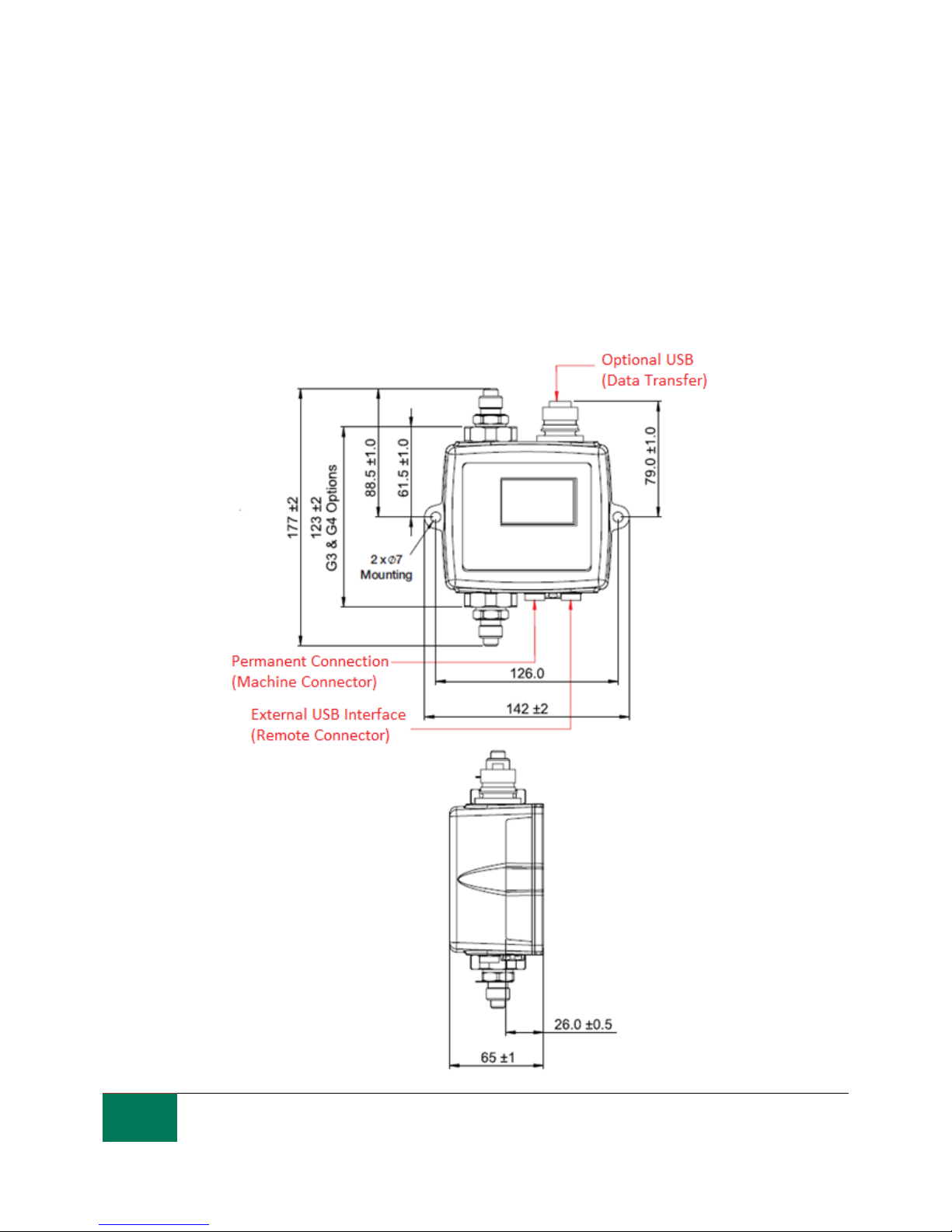
The LPM has two circular connectors located on the lower face of the unit. The USB Interface product
can be connected to either one depending on the installation configuration, see figure 6.1.
Pin
Colour
“Machine” Connector
“Remote” Connector
1
Yellow
RS485+/CANL/4-20mA(A)
RS485+
2
Pink
START INPUT
3 Green
RS485-/CANH/4-20mA(B)
RS485-
4
White
OUTPUT 1
5
Grey
I/O COMMON
6 Brown
OUTPUT 2
7 Blue
DC 0V
DC 0V
8
Red
DC +POWER
DC +POWER
6.1.2.1.1 Remote Connector
The “remote connector” is intended for temporary connection of an external communication device e.g.
LPMUSBInterface so as to allow data download, remote control or diagnostics using the LASPAC-View
software.
This is the circular connector furthest from the hydraulic connection, see figure 6.1.
This carries RS485 data and can also be used to power the unit temporarily in the event of a system
being shut down, thus no longer providing power to the unit.
This connector doesn’t send alarm signals as shown in the wiring diagram 6.7. If you require a USB
Interface to send alarm signals it has to be connected to the machine connector.
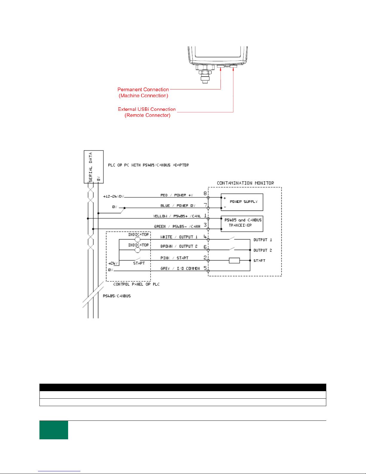
6.1.2.1.2 Machine Connector
The “machine connector” is intended for permanent connection to the PLC / machine that powers the
LPM during normal operation. It has power connections, a start signal input, two relay outputs, and a
data pair that can be set to RS485, CANbus or 4-20mA signaling modes.
This is the circular connector closest to the hydraulic connection, see figure 6.1.
NOTE: If CANBUS or 4-20mA option has been selected, standard communication with an RS485
adapter (e.g. USB Interface) on this port is no longer available.
The right hand port (remote connector) should be used if temporary connection is required.
NOTE: Start signal and relay outputs only apply to this connector.
18
As a policy of continual improvement, STAUFF reserves the right to alter the specification without prior notice.
201.031 Date of Issue: 06 November 2018
Figure 6.1 Connector Orientation
Figure 6.2 Machine Connector External Wiring Example
6.1.2.2 DC Power
DC power is connected to pins 7 and 8 of either circular connector (Red and Blue if using the pre-wired
cable). All the other signals are optional.
Item
Minimum
Maximum
Voltage
9V DC
36V DC
Current
200mA
19
As a policy of continual improvement, STAUFF reserves the right to alter the specification without prior notice.
201.031 Date of Issue: 06 November 2018
6.1.2.3 Machine Connector - Serial Interface
An RS485 or CANbus interface can optionally be connected to pins 1 and 3 (yellow and green). This can
be a PLC running customer software, or a PC with a RS485 adaptor running the supplied LASPAC-View
software. To provide a reference the RS485 0V connection should also be linked to the LPM 0V (as
shown on figure 6.3).
The standard LPM control protocol is Modbus RTU. Modbus is a freely available open standard for
industrial control. Adapters are available to interface to other industrial control busses. The standard
LASPAC-View software from Stauff itself uses Modbus to communicate with the LPM, but it is also
possible for customers to implement their own controllers (section Modbus).
The CANbus protocol can also be used, see separate LPM-CANbus manual.
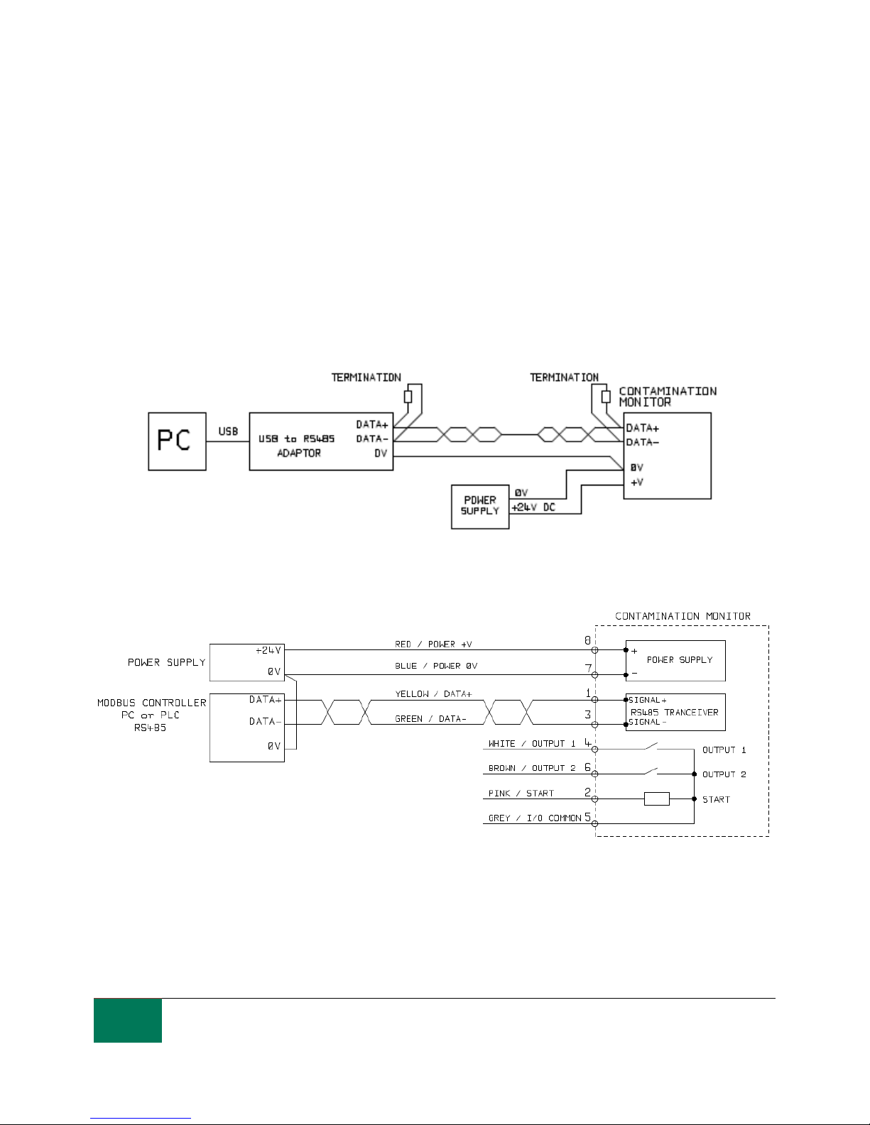
Figure 6.3a PC Control Example
Figure 6.3b Modbus Controller Example
Figure 6.3a shows a single LPM linked to a PC, using a USB-RS485 adaptor. Figure 6.3b shows a
slightly different method. 100 Ohm termination resistors should be fitted as shown for long cables, for
example over 10m. Twisted pair wiring should be used for any length over 2m.
20
As a policy of continual improvement, STAUFF reserves the right to alter the specification without prior notice.
201.031 Date of Issue: 06 November 2018
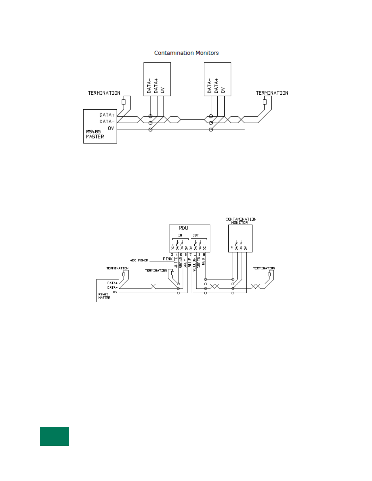
Figure 6.4 Multi-Drop Network Example
Figure 6.4 shows how to connect two or more LPM devices to a multi-drop RS485 network. Any
termination resistors should be fitted to the network cable ends only. Spurs off the main RS485 bus
should be kept as short as possible, e.g. below 2m. Normally the pre-wired 3m cable available for the
LPM would be used, with a junction box to connect to the RS485 trunk. Either individual DC supplies can
be used to power each LPM, or a single supply run through the trunk cable.
Figure 6.5 Remote Display Unit Including PC Controller Example
Figure 6.5 shows how to connect the LPM-RDU Remote Display Unit. The RDU is used when the LPM
location is not convenient for an operator. It can control and monitor a remote LPM, as well as allowing
an external controller to be connected to it (for data download, for example).

21
As a policy of continual improvement, STAUFF reserves the right to alter the specification without prior notice.
201.031 Date of Issue: 06 November 2018
6.1.2.4 Switched Input and Output Signals
The LPM has one switched input and two switched outputs. These can be used instead of, or in addition
to, the RS485 interface for command and control. The RS485 interface is more flexible but requires more
software work if LASPAC-View is not used (e.g. control from a PLC). An alternative is to control the LPM
via these switched I/Os, either from a PLC or using a manual switch and indicators.
Figure 6.6 Switched I/O Signals
In order to reduce wiring the input and outputs all connect together on one side (see Figure 6.6).
However they are optically isolated from the rest of the system so can be used to switch unrelated
signals.
6.1.2.5 Start Signal
The “start signal” is an opto-isolated input that can be used to start a test, it can be used to ensure
testing only occurs when the hydraulic system is running. For example, the start signal could be wired to
go on and off with the main hydraulic pump or with a solenoid valve that allows fluid flow. That way the
log does not fill up with invalid tests that were carried out with no flow.
This could be from a push button or a PLC output. The input accepts AC or DC signals, typically derived
from the DC supply voltage. The exact function of this input is determined by the Test Mode setting
(section tbc).
Item
Minimum
Maximum
Voltage
9V DC
36V DC
Impedance
10k Ohms
When the START signal transitions from OFF to ON, the unit will start a new test or restart any
test in progress.
At the end of the test, the state of the START signal is checked
If the START signal is still on at the end of a test, another test is started. So that testing continues
while the START signal is held on.
The switching off of the start signal will operate as a STOP command. That is, it will abort any
test in progress. It will continue to show and report the previous result.
This new operation mode applies whether or not continuous testing is enabled.

22
As a policy of continual improvement, STAUFF reserves the right to alter the specification without prior notice.
201.031 Date of Issue: 06 November 2018
So for example if “continuous testing" and "stop testing when clean" are both enabled, and if the
start signal is being held on throughout testing, then EITHER the start signal vanishing OR a
clean result can terminate testing.
This is not the same thing as the "start signal delimited test" option ("start signal defines test
duration" in user settings when enabled). This is for using the start signal to control the duration
of each *single* test, only.
Other ways to test are:
From the LPM front panel START button, if fitted (D Keyboard option)
Via LASPAC-View or PLC Modbus command
Periodic automatic testing according to a programmed test mode
6.1.2.6 Alarm Outputs
These are opto-isolated switches that can be used to signal external indicators, PLC inputs or other
equipment (e.g. pump on/off control).
The exact function of these outputs is determined by the Alarm Mode setting (section 6.3.3.9).
The outputs are “voltage free” contacts that can switch AC or DC signals up to 36V nominal (60V
absolute maximum peak voltage).
Item
Minimum
Maximum
Voltage
36V DC
Current
0.5A
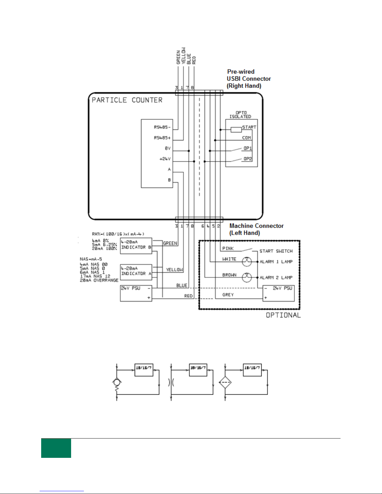
6.1.2.7 4-20mA Connection
See Figure 6.7 for a schematic.
The two 4-20mA outputs are sourced from the main supply voltage DC+. These may be connected to the
4-20mA inputs of a process indicator or a PLC. The 0V connection is then also normally connected to
the PLC 0V.
The 4-20mA outputs can be converted to 0-5V outputs by connecting a 250 ohm resistor between each
output and 0V. Similarly they can be converted to 0-10V outputs by connecting 500 ohm resistors.
For details of how the test results are represented by the 4-20mA signals, see section 6.4.3.
23
As a policy of continual improvement, STAUFF reserves the right to alter the specification without prior notice.
201.031 Date of Issue: 06 November 2018
Figure 6.7 4-20mA Example
6.1.3 Hydraulic Connection
1 High or Low Pressure Parallel Connection
Figure 6.8 LPM working pressure generated by hydraulic component
24
As a policy of continual improvement, STAUFF reserves the right to alter the specification without prior notice.
201.031 Date of Issue: 06 November 2018
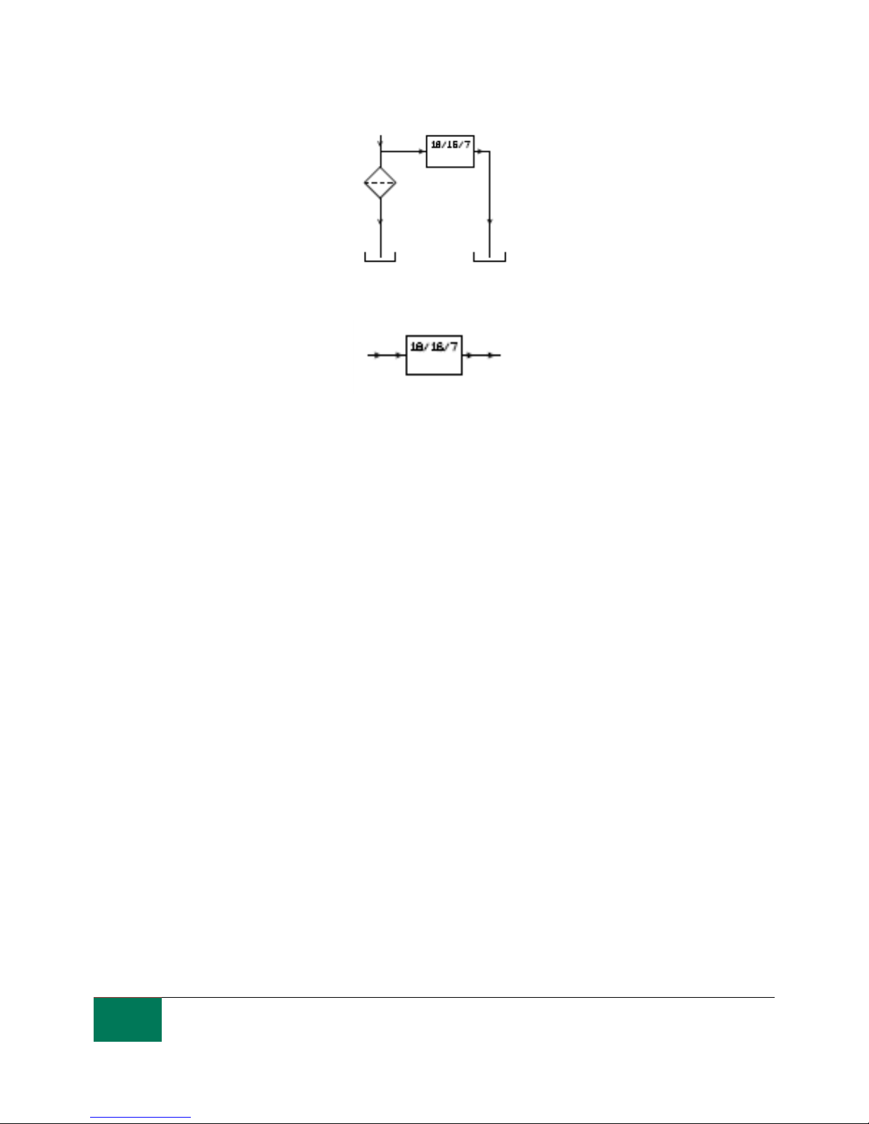
2 Low Pressure, Off-Line Operation
Figure 6.9 LPM working pressure generated by hydraulic component
3 Very Low Flow Systems
Figure 6.10 Entire system flow rate is within the range of the LPM
6.1.3.1 Flow Rate
For the majority of systems, a differential pressure of a few Bar will generate an in-range flow for an LPM
connected using two 1.5 meter lengths of microbore pressure hose. The required differential pressure
can be obtained by taking advantage of an existing pressure drop within the system. Alternatively one
can be created by inserting a check valve. The LPM can then be connected across this differential
pressure source.
6.1.3.1.1 Detailed Calculations
In general the flow rate of fluid through the LPM needs to be kept within the range of the unit (see
hydraulic specification 3.2). The LPM measures the flow during operation, so this can be used to check
that the flow is correct.
A flow that is out of range will be indicated by a fault code (see section 7.2).
Note: Results taken with out-of-range flows are not logged.
The flow is entirely generated by the differential pressure between the ends of the pipes used to connect
the LPM. The pressure needed to generate an in-range flow can be estimated by assuming a target flow,
and determining the resulting pressure drop across the LPM and connection piping. Use Figure 6.10 on
page 24 to lookup the LPM pressure drop, and manufacturers’ data to lookup the piping pressure drop at
the desired flow. The sum of these two pressures is the pressure needed.
The user connects the LPM between two points in the hydraulic circuit that have this pressure difference.
In order to use the graph:
Determine the working viscosity of the fluid, e.g. 30 cSt
Decide on a desired flow rate. 200ml/minute is normally used since this is in the middle of the
LPM flow range. But 100ml/minute is also suitable and uses less oil
Use the figure 6.11 to look up the pressure drop, across the LPM ports, at this flow rate and
viscosity. E.g. at 30cSt and 200ml/minute, this is 0.4 Bar. The maximum and minimum allowed
differential pressures can also be determined using the 400ml/min and 20ml/min lines,
respectively.

25
As a policy of continual improvement, STAUFF reserves the right to alter the specification without prior notice.
201.031 Date of Issue: 06 November 2018
Determine the additional pressure drop caused by the piping used to connect the LPM. This may
be negligible for 1/4 inch piping and over, but is very important for microbore hoses. This
information can be found in the manufacturers catalogues. In the case of microbore hoses, at 30
cSt these have a pressure drop of around 10 Bar per meter per lpm of flow. So a 2m total hose
length would add a pressure drop of 2 × 10 × 0.2 = 4 Bar. (So in this case the pressure-flow
relationship is mainly dependent on hose resistance).
Add the LPM pressure drop to that of the hoses, e.g. 4 + 0.4 = 4.4 Bar
When the required pressure drop has been found:
See the figures at the start of this section for examples of where the LPM could be connected
If there is a pair of connections in the hydraulic circuit that operates with a differential pressure
near to that calculated, then the LPM can be connected there
Alternatively, create the pressure drop by modifying the hydraulic system. For example, insert a
check-valve in the circuit with a 4 bar spring. The "component’’ could also be a filter, a restrictor
or even a piece of piping if it has a suitable pressure drop across it.
If none of these options is feasible, then an active flow controller will likely be needed, see
6.1.2.3.
Otherwise connect the LPM across the points identified; taking care to maintain an upward flow
of oil through the unit (this reduces trapped air).
Of course in a real system the pressure and viscosity will vary with temperature and operating
conditions. But since the working flow range of the LPM is very wide, this should not be a problem
provided it remains within range. On the graph the area between upper and lower lines represents the
usable operating region for the LPM, with the middle line being ideal. The differential pressure and the
viscosity can vary from the ideal, provided the system stays within the upper and lower lines. This
ensures the flow stays within the working range of 20 - 400 ml/min. It can be seen that the unit will
accommodate a 20:1 variation in either viscosity or differential pressure during operation.
Figure 6.11 Differential Pressure vs Fluid Viscosity, for various flow rates

26
As a policy of continual improvement, STAUFF reserves the right to alter the specification without prior notice.
201.031 Date of Issue: 06 November 2018
6.1.3.2 Manual Flow Control
Another possibility is to fit a simple manual flow control (flow restrictor) to the outlet of the LPM.
This should only be done where the available pressure is less than twice the maximum value
calculated. This is because the small orifice size needed to control the flow from a pressure larger
than this has a risk of blockage.
The flow controller must be fitted to the outlet only. If fitted to the inlet it will have a filtering effect.
The flow controller must be fitted directly to the LPM outlet port.
6.1.3.3 Active Flow Control
This is only needed for operation at high differential pressures, where a too-high flow would otherwise be
generated.
A pressure compensated flow control valve is fitted to the LPM drain outlet. A suitable valve is the LPMDAV (see 2.1.2), but other ones can be used too. This has the effect of a “flow limiter”, maintaining a
constant flow rate even with a varying inlet pressure (provided this pressure stays above a minimum
working value). Below this pressure the valve is wide open so has little effect, i.e. the flow will be less
than the 200ml/min controlled value. This “minimum working value” will be typically 5-10 bar but will vary
with viscosity. For these lower pressures a flow control valve is not needed and other methods are better
used to control flow as previously described.
Figure 6.12 LPM flow actively regulated
6.2 General Operation
6.2.1 Physical Checks
Oil leaks on and around the unit
Fatigue in hoses and pipework that might then leak when under system pressure
6.2.2 Front Panel Operation
6.2.2.1 Status LED
All LPM versions have a multi-colour indicator on the front panel, which is used to indicate the status or
alarm state. LPM-D versions also have a screen that changes colour. The alarm thresholds can be set
from LASPAC-View via the serial interface.

27
As a policy of continual improvement, STAUFF reserves the right to alter the specification without prior notice.
201.031 Date of Issue: 06 November 2018
Figure 6.13 Front panel of D version (left) and Non-D version (right) LPM2.0
Colour
Shows
Green
Indicates that the test result has passed, i.e. none of the alarm
thresholds were exceeded
Yellow
Indicates that the lower cleanliness was exceeded, but not the upper
one
Red
Indicates that the upper cleanliness was exceeded
Blue
Indicates that the upper water content limit was exceeded
Red/ Blue
Alternating
Indicates both cleanliness and water content upper limits exceeded
Violet
Indicates that the upper temperature limit was exceeded
Red Flashing White
Various fault codes can be indicated by the LED turning red and then
flashing white a number of times (Section 7.2.1)
Please note: If the codes seem confusing, note that a given colour will only ever be seen if the
corresponding limit has been specifically set by the user. So for example if a maximum temperature limit
has not been set, the violet indication will never be seen. If all that is wanted is a "green or red’’ light, that
can be arranged by simply setting only the cleanliness threshold maximum limit.
If the upper temperature alarm is set, this takes priority over the Contamination and Water alarms. In the
event of an over temperature condition, the LED will turn violet only, whether or not there is also a
contamination or water alarm condition. The rationale is that an over-temperature condition could be
immediately catastrophic for the hydraulic system.
6.2.2.2 Front Panel Operation
6.2.2.2.1 Result Display
LPM-D models have a 6 button keypad and a small graphical LCD. This allows the display of the test
result (current cleanliness level, with water content and temperature if applicable).
The graphical format allows a full display of all codes of the standards supported.

28
As a policy of continual improvement, STAUFF reserves the right to alter the specification without prior notice.
201.031 Date of Issue: 06 November 2018
The unit powers up in ”Display Mode”. This displays the test result in the selected format. The table
below shows those available.
The screenshots in the right column are the “detailed” version of the display additionally showing the
particle counts and flow rate. The particle sizes and count representation are automatically matched to
the selected format.
Format
Simple View
Detailed View
ISO4406:1999
NAS1638
AS4059E Table 1
AS4059E Table 2
ISO11218
There is also a “History” screen which shows the last 10 results.
The operator can switch between these screens using the ▲ and ▼ keys.
Figure 6.14 History Screen
The progress of a test is denoted by the horizontal line; it grows from left to right as the test progresses.
When it reaches the right hand side a new result is generated.

29
As a policy of continual improvement, STAUFF reserves the right to alter the specification without prior notice.
201.031 Date of Issue: 06 November 2018
6.2.2.2.2 Diagnostics Display
Press ◄ or ► to show the diagnostics displays (used when diagnosing problems) shown in figure 6.15.
Then switch between the diagnostics screens using the ▲ and ▼ buttons.
Completion shows a number from 0 to 1000, indicating the test progress.
FLOW ml/min provides an approximate indication of flow rate, updated after each test.
NOTE: This is not a calibrated flow meter and is for indicative purposes only.
This can be helpful when installing the unit or checking operation, to ensure that the flow rate is within
the limits of the unit. The other items are mainly of use to assist in support when reporting problems.
The STATUS line shows the current state of the unit. Any errors such as LOW FLOW will also appear
here (corresponding to the front panel LED fault codes).
The second screen shows diagnostics relating to Modbus serial communications traffic. External Comms
Errors are those between a connected PC and the LPM. Internal Comms Errors are internal to the unit,
showing communications between the LPM keyboard/display circuit board and the sensor itself.
The third screen shows diagnostics related to CAN bus communications. For more details refer to the
separate LPM CAN bus manual.
General Modbus CAN Bus
Figure 6.15 Diagnostics Screens
6.2.3 LPM removal and Product Maintenance
When removing the LPM from the system ensure the system pressure is shut off from the LPM.
Blockages
If a suspected blockage occurs then flush system fluid in the reverse direction of the LPM.
If this doesn’t solve the problem then try using Iso-Propyl Alcohol or Petroleum Ether, flushing in
the standard and reverse flow direction.
If this doesn’t solve the issue then send to Stauff for investigation.
6.3 LPM Control
The LPM can be controlled using the remote control facility included in the LASPAC-View software
package, installed on a computer. Alternatively customers can use their own computer software.
Since the LPM includes a built-in data logging memory, operators can make use of the remote control
facility in one of two ways:
− Direct Online Operation
The LPM is permanently connected to a computer while tests are carried out. The operator can set
parameters, type a label and initiate the test. They can then monitor the progress of each test. Each test
result is displayed and downloaded into the test database as it is completed.
− Disconnected Operation

30
As a policy of continual improvement, STAUFF reserves the right to alter the specification without prior notice.
201.031 Date of Issue: 06 November 2018
Here the LPM operates as a standalone item, performing tests on a schedule or under external
command from a control system. If a permanent record of the results is needed, an operator can connect
a computer and use LASPAC-View to download the accumulated test data. The LPM can hold up to
4000 tests in the memory.
6.3.1 Computer Connection
The connection is made using an RS485 adaptor connected to the computer or control device.
The LPMUSBInterface is included as a pre-wired solution for USB (all modern laptops and PCs). Make
the connection, start LASPAC-View running and then apply power to the LPM.
Figure 6.16
To access the Remote Device facility in LASPAC View, press the Remote Control button (Figure 6.17)
on the toolbar. The Connect dialogue will then appear (Figure 6.18).
Figure 6.17
Figure 6.18
The first time that this is done, the correct communications port (COM port) on the computer has to be
selected, as detailed below.

31
As a policy of continual improvement, STAUFF reserves the right to alter the specification without prior notice.
201.031 Date of Issue: 06 November 2018
− The program scans the computer for available ports, and puts them in a list to choose from - this list is
in the box above the Connect button. Press the arrow on the right hand side of this box and choose the
connection on your computer.
− All working communication ports of the computer are available for selection. Select the one used to
connect the LPM, and then press OK. If you are unsure which port is correct, the device name should be
next to the COM port number. When communication has been established successfully, the remote
control dialogue will appear. After a successful connection, the COM port will be remembered for next
time and will appear preselected in the dialogue. If no COM ports appear, please refer to the fault finding
section the manual (7.2).
6.3.2 PC Software Operation
The Remote Control dialogue allows an operator to manually control the LPM from a laptop, using the
LASPAC-View software. It can also be used to download test results that have accumulated during
autonomous (disconnected) operation.
Figure 6.19
To perform a test, first optionally edit the Test Reference and press Apply to register the new value. This
is a descriptive label which can be used to identify or group the test later (along with the test number and
test time/date). An example would be a machine number or customer name. The Test Reference can be
up to 15 characters in length.
When connected the LPM status should show "Ready". The operator can then press the Start button to
begin the test. The progress bar shows how much of the test has been completed.
The test can be abandoned at any time by pressing the Stop button. If the Start button is pressed during
a test, then the current test is abandoned and a new one started. When the test has finished, the Result
area will display the contamination level in the set format and water content and temperature (if
applicable).
After a test the Test Number is automatically incremented and the status of the test is displayed. If the
status is Ready then the operator can press the Start button again to begin a new test.
It is also possible to configure the LPM to automatically begin another test, after an optional delay. In this
case the status will be Testing or Waiting.
The LPM incorporates a data logger, so previous test results can be downloaded into the test database
using the Download New and Download All buttons. The difference between these is that Download New

32
As a policy of continual improvement, STAUFF reserves the right to alter the specification without prior notice.
201.031 Date of Issue: 06 November 2018
only transfers results that have never been downloaded before. Download All transfers all results that
are stored in the LPM. Erase Log deletes the test results from the memory of the LPM, see figure 6.19.
When the user has finished operating the LPM the dialogue can be dismissed using the close control
(the "X" at the top right corner of the dialogue) or by pressing the Esc key. Pressing the Settings... button
brings up the Remote Device Settings dialogue.
6.3.3 Settings
The LPM can be reconfigured using the Remote Device Settings dialogue. This is normally done as part
of the installation or commissioning process.
After making any changes, pressing the OK button will update the LPM with the new settings. Or press
Cancel to leave the settings as they were.
Figure 6.20
NOTE: The LPM has been designed to be a very flexible product, so has a wide range of settings and
operating modes. However the shipped defaults are suitable for most applications and many users can
skip this section. Actual operation is straightforward even when advanced settings are used during initial
configuration.
NOTE: Some items may be missing depending on the options fitted to the LPM.

33
As a policy of continual improvement, STAUFF reserves the right to alter the specification without prior notice.
201.031 Date of Issue: 06 November 2018
6.3.3.1 General
Some general information about the connected LPM unit is available. The Identification shows the LPM
serial number and software version. The serial number, together with the test timestamp, uniquely
identifies the test record. These two parameters are the ones used to avoid duplication of test records.
Current Time shows the time set on the LPM. It is important that this is correct since this is used to
timestamp the tests. Pressing the Set button automatically synchronizes the LPM time to that on the
computer.
The calibration area displays the date last Calibrated and the next Calibration Due date.
6.3.3.2 Test Number
The Test Number can be used to help identify a test within a sequence. However it is automatically reset
when the LPM is powered up, so instead relying on the timestamp (date and time of test) and test
reference is preferred.
Figure 6.21
NOTE: if the LPM is power cycled at any point then the test numbering sequence automatically resets
and begins again.
6.3.3.3 Test Duration
The length of the test is controlled by the Test Duration, see figure 6.21 for location.
The factory set value of 2 minutes is suitable for most applications, but the user is free to set a different
value. Shorter times will make the LPM more responsive to short-term fluctuations in contamination
level. It will also result in less consistent results for the large particle sizes and clean systems, due to
statistical fluctuations in the number of particles counted.
Longer tests will allow more “stable” results in very clean systems and for the larger particle sizes, since
there will be a larger total number of particles counted during the test. This means that any fluctuations
have less of an effect on the test result.
6.3.3.4 Result Display
Use the selector to choose the preferred display Format (ISO, NAS etc.). This selection is not just
cosmetic since it also determines how the cleanliness alarm targets are to be interpreted, if these are
used. See figure 6.21 for the location, it is defined as the format.
6.3.3.5 Simulated Test
This setting can be used when there is no flow available but communications need to be tested. This is
the box ticked in figure 6.22

34
As a policy of continual improvement, STAUFF reserves the right to alter the specification without prior notice.
201.031 Date of Issue: 06 November 2018
Figure 6.22
6.3.3.6 Low Flow Alarm Disabled (Clean Systems)
It is worth reinforcing that the primary function of the product is to produce a measurement of
cleanliness, and not act as a flow meter. If the unit produces a contamination measurement, then
the flow rate is sufficient enough for it to do so.
The LPM needs particles to pass through the flow cell to calculate flow, the dirtier the system is,
the more statistically accurate the flow output becomes.
Conversely, when placed on a very clean system the unit can have difficulty in working out the
flow due to the very low number of particles passing through the flow cell.
To overcome this, the test has to fulfil certain conditions to create a valid result.
It the low flow alarm has been disabled there must be a minimum of 20 particles >4micron seen
during the test for the flow reading to be shown and the test result to be valid.
If there are less than 20 particles >4micron during the test then the LPM will alarm/fault code
even if the low flow alarm has been disabled.
Note: If the low flow alarm has been disabled, it is preferred that the LPM is installed in such a
way that if the system is shutdown (zero flow) the LPM is also shut down so as not to measure
stagnant fluid and provide erroneous readings.
It may be necessary that the low flow indicator is turned off if filtration is below 10um (ISO
14/12/10 (NAS Class 4)), see figure 6.22 for location.
6.3.3.7 Continuous Testing
Figure 6.23

35
As a policy of continual improvement, STAUFF reserves the right to alter the specification without prior notice.
201.031 Date of Issue: 06 November 2018
In the Continuous Testing area are settings which control how the LPM decides when to perform and log
a test. Selecting Test Continuously makes the LPM automatically repeat the test, according to the
specified Test Interval.
a) Setting an interval longer than the test duration; results in the test being repeated upon each
expiry of that interval. For example, setting a Test Duration of 1 minute and a Test Interval of 10
minutes, results in a 1 minute test performed every 10 minutes.
NOTE: Test time is part of interval time
b) Setting the interval to a value less than the Test Duration (for example zero); results in a new test
being started immediately after a test finishes.
Log Continuous controls whether tests are logged during continuous testing. This is to avoid the test log
being cluttered by potentially large numbers of unwanted test results. If Log Continuous is not selected,
then only the "final" test in a sequence is logged (see Alarm Modes section and "Stop Testing When
Clean" below).4
If continuous logging is used, then the Log Interval can be set to control the proportion of tests that are
actually logged. For example the LPM could be set to test every 10 minutes, but only log a result hourly.
The log interval, test interval and test duration are distinct parameters that work together to control the
test and data logging. So that, a test duration of 2 minutes, a test interval of 10 minutes, and a log
interval of 1 hour could be individually set. This would result in 2 minute long tests, repeated every 10
minutes, with a test logged hourly.
NOTE: the log interval must land on a test interval or an error will occur, for example the test interval
cannot be 2 minutes and the log interval 3 minutes.
Stop Testing When Clean- This is a feature intended for cleaning rigs or "filter trolley" type applications.
The LPM continues testing until the fluid is "clean", at which point an alarm is signaled and testing stops.
Ignore Initial Tests- on start up the number selected here is the number of tests that are ignored before
results are logged. This is designed for systems that are particular dirty or turbulent on startup and it
allows the system to stabilize.
Confirm Target Level before Stopping- this helps to ensure that a test sequence is not terminated too
soon, when there are still a few large particles in the system. When selected, the number in the box is
how many successive "clean" results are needed before testing halts.
4
This feature is intended for a "Filter Trolley" type application where system runs a pump until the oil is
sufficiently clean. Typically only the final "clean" result requires logging.
6.3.3.8 Changing Communication Protocols
Figure 6.24

36
As a policy of continual improvement, STAUFF reserves the right to alter the specification without prior notice.
201.031 Date of Issue: 06 November 2018
Selecting the communication button allows you to change how the LPM communicates. See figure 6.25
for the options.
Figure 6.25
Selecting a machine interface fixes the output for the machine connector, for example selecting CANbus
means that you can no longer use the machine connector to communicate in Modbus (the default). If you
wish to change back or to a version of 4-20mA then you have to connect to the LPM via the Remote
Connector.
See section 6.4 for information on how to communicate with the LPM in the different protocols.
6.3.3.9 Alarms
The LPM has two switched "alarm" outputs that can be used to signal external equipment in various
ways, according to the test results and the alarm settings. There is also a multi- colour front panel light
which indicates how the result compares to the set alarm thresholds.
The alarm settings are comprehensive and flexible, allowing the LPM to be us ed in many different
scenarios.
6.3.3.9.1 Alarm Levels
The various alarm thresholds are set in the Contamination Code Target / Alarm Levels area of the
dialogue.
Alarms can be set on combinations of cleanliness codes, water content and temperature. The available
codes, and their interpretation, vary according to the set test Format. For example it is possible to set a
threshold of "NAS 11" or "ISO 18/16/15" or "AS4059E 8B-F", etc.
In general there are upper and lower limits that can be set for the cleanliness level, also for water content
and temperature if applicable. An alarm, if enabled, will become active if any of the associated
(upper/lower) limits are exceeded. However if a field is left empty (blank) this is interpreted as a "don’t
care" setting.
In the example Figure 6.21 the Upper Alarm is exceeded if the 4μm count is greater than ISO code 23,
or the 6μm greater than ISO code 22, or the 14μm count greater than code 18, or the water content is
greater than 80% RH, or the temperature is greater than 65°C. The lower alarm is never triggered since
all the settings are empty.

37
As a policy of continual improvement, STAUFF reserves the right to alter the specification without prior notice.
201.031 Date of Issue: 06 November 2018
Figure 6.24
ISO4406:1999 Alarm Levels
ISO4406:1999 represents cleanliness using codes for the number of particles greater than 4, 6 and
14µm. These codes can be used as limits for the alarms by selecting the ISO4406:1999 test Format and
then entering values as required. As an extension to ISO4406:1999 it is also possible to specify codes
for the other measured sizes too. If this is not needed then the entries can be left blank.
NAS1638 Alarm Levels
Figure 6.25
NAS1638 can be used by selecting this as the test Format. The headings and boxes for the available
settings change appropriately. NAS1638 represents the overall cleanliness level as a single code, this
being the highest of the individual codes generated for each defined particle size. Hence we have the
option of setting a limit on this overall contamination class (the Basic Class), or we can set individual
limits on any combination of the classes for the defined particle size ranges.
AS4059E Table 2 Alarm Levels
Figure 6.26
AS4059E Table 2 uses letters instead of numbers to indicate the particle size range, so the settings are
labelled appropriately. The standard specifies ways to represent a cleanliness level using only a subset

38
As a policy of continual improvement, STAUFF reserves the right to alter the specification without prior notice.
201.031 Date of Issue: 06 November 2018
of the available particle sizes, for example B-F. The user can achieve this by only entering settings for
the sizes desired, leaving the others empty. So a limit of AS4059 7B-F could be represented simply by
entering a value of 7 for B, C, D, E and F.
AS4059E Table 1 / ISO11218 Alarm Levels
Figure 6.27
These two standards are similar except for terminology and reporting format. The actual numeric sizes
and class thresholds are the same.
6.3.3.9.2 Alarm Mode
Figure 6.28
The Alarm Mode sets the precise function of the two switched alarm outputs of the LPM.
This allows the LPM to be used in a variety of situations. Note that the conditions under which the
outputs are turned on are also displayed above the Alarm Mode selector, for each setting.
NOTE: These outputs are distinct from the front panel LED, and that the set alarm mode does not affect
the LED. The set alarm mode determines the function of the two switched outputs only. This setting and
this entire section can be ignored if these outputs are unused, i.e. the user has not connected them to
anything.
New modes are occasionally added after a customer request, this means that modes may not all be
implemented unless using the latest firmware revision.
Alarm Mode 0: Warning-Alarm
Output 1
Output 2
Turns on When
>Lower
>Upper
Intended Function
Warning
Alarm

39
As a policy of continual improvement, STAUFF reserves the right to alter the specification without prior notice.
201.031 Date of Issue: 06 November 2018
This allows the LPM to switch external warning lights or alarms. Output 1 is the “Warning” output,
switching on if any of the Lower limits are exceeded. Output 2 is the "Alarm’’ output, behaving similarly
for the upper limit.
Alarm Mode 1: Clean-Dirty
Output 1
Output 2
Turns on When
≤Lower
Upper
Intended Function
Clean
Dirty
This could be used in a cleaning system that attempts to maintain a cleanliness level by switching a
pump on and off.
Output 1 is the “Clean” output, coming on when the result is less than or equal to the lower (“Clean”)
limit. This could be used to stop a cleaning pump.
Output 2 is the “Dirty” output, coming on when the result is greater than the upper (“Dirty”) limit. This
could be used to start the cleaning pump.
Alarm Mode 2: Green-Amber-Red
Output 1
Output 2
Turns on When
<Upper
>Lower
Intended Function
Green
Red
This mode encodes the result in such a way that the internal alarm relays can be used to drive an
external remote 3-colour LED indicator. This is a special type of LED containing both red and green
emitters, which could be mounted in a control panel. This external LED will then turn green / amber / red
according to the test result – in a similar way to the built-in one. Output 1 (“Green”) is turned on when the
result is less that the upper limit. Output 2 (“Red”) is turned on when the result is greater than the lower
limit. If the result is in between, both outputs are turned on and the LED colour will be amber (i.e. a
mixture of red and green light).
Alarm Mode 3: Particles-Water
Output 1
Output 2
Turns on When
Cleanliness>Upper
Water>Upper
Turns off When
Cleanliness ≤lower
Water ≤lower
Intended Function
Cleanliness Alarm
Water Alarm
This is used when separate alarm outputs are needed for particles (cleanliness) and water content.
This mode is able to use both upper and lower limits such that the outputs have “hysteresis”. If only the
upper or lower limit is required, then both upper and lower limits should be set to the same value.
Alarm Mode 4: Continue-Clean
Output 1
Output 2
Turns on When
>Lower
≤Lower
Intended Function
Continue Testing
Stop Testing / Clean
This is used for a "cleaning" application where a signal is needed to stop testing (for example to stop a
pump or signal an external controller).
Alarm Mode 5: Tested Not-Clean
Output 1
Output 2
Turns on When
Test Complete
>Lower
Intended Function
Test Complete Signal
“Not Clean” Signal

40
As a policy of continual improvement, STAUFF reserves the right to alter the specification without prior notice.
201.031 Date of Issue: 06 November 2018
This is used when controlling tests from a PLC using switched outputs. The PLC gives a start signal,
then monitors the “Test Complete” output. If the test has failed it can detect this with the ”not clean”
signal.
“Continuous testing”’ should not be selected for this mode.
Alarm Mode 6: Testing Not-Clean
Output 1
Output 2
Turns on When
Testing
>Lower
Intended Function
Test in progress Signal
“Not Clean” Signal
This is similar to mode 5 above. The difference is that output 1 is active during the test and turns off at
test end.
“Continuous testing”’ should not be selected for this mode.
Alarm Mode 7… Customer Requested Modes
Other alarm modes will be defined as and when customers request them.
6.4 Standard Communication Protocols
6.4.1 Modbus
The LPM can be controlled via commands on its serial (RS485) interface, using the Modbus RTU
protocol. It is possible to control every aspect and setting of the LPM, as is done by the Stauff LASPACView control software. All results and counts are available in all supported formats. We suggest using
LASPAC-View to initially configure the LPM and check it is performing correctly, and then the customerwritten software only has to read the test results. This could be used to integrate the LPM measurements
with a general machine control, vehicle control or factory monitoring system.
Customers wishing to implement their own Modbus controller software will need to refer to the rest of this
section with further details in section 11.1 and 11.2.
The simplest arrangement is to configure the LPM to test continuously, with a set interval between tests.
For example; a Test Duration of 2 minutes and a Test Interval of 10 minutes.
The Start Testing Automatically selection can be used so that the unit does not require a start signal.
Then, the most recent test results can be read from the appropriate Modbus Registers.
Register
Function
56
4μm Result Code
57
6μm Result Code
58
14μm Result Code
6.4.1.1 Set Up
Protocol Type
RTU (not ASCII)
Data Bits
8
Stop Bits
1
Parity
Required, Even or none
Baud
Auto-sensing 1200-115200
Signaling
RS485
Node Address
4 (or user set)
Figure 6.29 Settings

41
As a policy of continual improvement, STAUFF reserves the right to alter the specification without prior notice.
201.031 Date of Issue: 06 November 2018
6.4.1.1.1 Communications Check
You should be able to read the product ID code from register 0 (from Modbus node address 204). The
product ID code is the value 54237 (decimal) or 0xD3DD (hexadecimal).
6.4.1.1.2 Result Format
The LPM can present results in several different industry formats (ISO, NAS etc.) The format required
can be most easily set using LASPAC-View; however it is also possible to set it via Modbus. To do this,
write the required value 0-4 from table 6A to the TEST FORMAT register 19. The factory set value is 0
(ISO 4406:1999).
The selected format does not affect the particle count values, but does completely change the
interpretation of the result codes and set limits, if used.
Note: If the format is changed, then any set alarm limits must be changed too since these will refer to the
old format. E.g. a limit of “NAS 11” cannot be directly expressed using the ISO4406 standard.
Value
Format
Main Class
Example
Individual Codes
Example
0
ISO 4406:1999
21/20/17
1
NAS 1638
NAS 12
(12 11 11 7 6)
2
AS4059E Table 2
12A-F
12A/12B/11C/11D/7E/6F
3
AS4059 Table 1
Class 12
12 11 11 7 6
4
ISO 11218 Draft
ISO (12)
12 11 11 7 6
Table 6A TEST FORMAT Register 19
6.4.1.2 Result Codes
The most recent measurements are presented as numeric codes (i.e. numbers) according to the
selected TEST FORMAT. These codes can be read from registers 56-63, as per Table 6B.
Register
ISO 4406
Code
AS4059E Table 2
Class
NAS1638/ AS4059E Table 1/
ISO 11218 (Draft) Codes/
Classes
56
≥4µ
Basic
Basic
57
≥6µ
-
-
58
≥14µ
A
5-15
59
≥21µ
B
15-25
60
≥25µ
C
25-50
61
≥38µ
D
50-100
62
≥50µ
E
100+
63
≥70µ
F
Table 6B RESULT CODES Registers 56-63

42
As a policy of continual improvement, STAUFF reserves the right to alter the specification without prior notice.
201.031 Date of Issue: 06 November 2018
6.4.1.2.1 Null Values
For all formats, the special value -32768 (0x8000 hex) is used to represent a “null” or “no result”
condition. This enables “No Result” to be distinguished from a 0/0/0 ISO code, for example. “No Result”
could be due to an error condition, or to a measurement not having been commanded yet. This
convention is also used for other parameters such as temperature and water content measurements,
where applicable.
NOTE: User written programs should take note, to avoid displays like -32768/-32768/-32768 appearing
on their front panels.
6.4.1.2.2 ISO4406
ISO 4406 defines a set of code values to represent ranges of counts of particles greater than the
nominated sizes of ≥4, ≥6 and ≥14μm(c). The LPM can display codes from 0 to 24. The three-part code
is available in the first 3 RESULT CODES.
We additionally make available equivalent codes for the other sizes from 21 to 70μm(c), as per Table 6B.
6.4.1.2.3 NAS 1638/ AS4059E-1/ ISO11218
These assign code numbers for the particle counts in each size range shown in the table. The “basic”
class is then the highest of these individual codes. The basic class is in the first register, with the
individual classes made available in the registers shown.
For these standards there is a complication in that they all define an additional class “00”. This is an
extra “cleaner than class 0” class. We distinguish this from 0 using the numeric value -1. Negative
numbers are represented in a Modbus register using the “twos complement” notation. If the user
program interprets this as a positive number it will appear as 65535 (0xFFFF hex).
Classes range from 00(-1) to 12.
6.4.1.2.4 AS4059E-2
AS4059E Table 2 also has some similarities to NAS1638. In terms of the representation in Modbus
registers, the main differences are an extra 4-6μm(c) size range and the addition of an extra “000” class.
This is represented using the number -2. If the user program interprets this as a positive number it will
appear as 65534 (0xFFFE hex).
6.4.1.2.5 Temperature and Water Content Measurements
These are contained in the TEMPERATURE register 33 and the RH (relative humidity) register 34.
These are scaled by a factor of 100, so that values of 12.34°C and 56.78% RH would be represented by
values of 1234 and 5678 respectively. The temperature can go negative, in which case the usual “twos
complement” representation is used. Most controllers should have a facility for reading “signed integers”
encoded in this way (these will appear as large positive numbers if interpreted instead as positive
numbers, for example 65535).
The special value -32768 (0x8000 hex) is again used to indicate ``No result’’, as per the contamination
result codes. This could be due to a sensor failure or to the unit still in the process of powering up.

43
As a policy of continual improvement, STAUFF reserves the right to alter the specification without prior notice.
201.031 Date of Issue: 06 November 2018
6.4.1.3 Performing Tests
6.4.1.3.1 Commanding Test Start
If the LPM is monitoring a single machine, it will normally be configured to test continuously and
automatically, so that the contamination measurement can be read out at any time as described above.
However some applications need a defined test start and test end, for example end-of-line production
testing, where each result relates to a separate item being tested.
These applications can simply use a push button (or relay) wired to the LPM start signal, or the front
panel push button, or can be commanded programmatically via Modbus.
To start or restart a test, write the value 1 to the command register 21. The test duration can be set using
LASPAC-View before installation, or alternatively write the required test time (in seconds) to the TEST
DURATION register 18.
6.4.1.3.2 Test Status
A test status code is available in register 30. This contains a number indicating the current state of the
LPM, according to section 7.2.2, table 7A. This allows a system to remotely monitor the LPM operation, if
desired, allowing more specific diagnostics.
NOTE: the fault conditions are also indicated on the front panel LED, while “No Result” in the case of a
fault is indicated using special result values as previously described.
6.4.1.3.3 Test Completion
The TEST COMPLETION is indicated by register 36. This contains a number between 0 and 1000
indicating the test progress (this is also used by LASPAC-View to drive the test progress bar).
6.4.1.4 Particle Counts
Some quantities are (or may become) too large to fit into a single 16-bit register. For example the 4μm
particle count could easily be more than 65535. These items are represented using two consecutive
registers; the combination makes up a 32-bit integer. For example, the value of such a 32 bit unsigned
integer stored in the two registers 40 and 41 may be calculated using the formula:
𝑣𝑎𝑙𝑢𝑒 = (65536 × (𝑟𝑒𝑔𝑖𝑠𝑡𝑒𝑟 40)) + (𝑟𝑒𝑔𝑖𝑠𝑡𝑒𝑟 41)
The particle counts are stored in registers 40-55, as shown in Table 6D. There are 8 register pairs; each
pair encodes one count channel as a 32 bit integer, using two consecutive Modbus registers as
explained above. The Counts are per 100ml.
Particle sizes are expressed below according to ISO4406:1999, i.e. equivalent projected area diameter.
The sizes have been chosen so that all supported coding standards (NAS, ISO...) can be derived from
them. The counts are all cumulative.
Differential counts can be derived by subtraction. E.g., the NAS 5-15μm count could be calculated by
subtracting the ISO 6μm(c) count from the 14μm(c) count.

44
As a policy of continual improvement, STAUFF reserves the right to alter the specification without prior notice.
201.031 Date of Issue: 06 November 2018
Number
Function
Comment
40-41
≥4µm (c)
42-43
≥6µm (c)
≥5µm (NAS)
44-45
≥14µm (c)
≥15µm (NAS)
46-47
≥21µm (c)
≥25µm (NAS)
48-49
≥25µm (c)
50-51
≥38µm (c)
≥50µm (NAS)
52-53
≥50µm (c)
54-55
≥70µm (c)
≥100µm (NAS)
Table 6D Particle Count Registers
6.4.1.5 Alarms
6.4.1.5.1 Alarm Mode
The LPM includes two relay outputs that can optionally be used for signaling the state of the unit. These
are normally used in “stand-alone” applications where the Modbus interface is not used (since a Modbus
controller / PLC already has all the exact results available in digital form and can work with these
directly.)
There are a number of preset “modes” that determine the exact function of the relays. Refer to the alarm
mode section for more details (6.3.3.9.2).
These modes are normally set at installation time using our PC software package LASPAC-View. But it
is also possible to use Modbus to set the operating mode of these relays, by writing the corresponding
integer to the alarm mode register 26.
6.4.1.5.2 Alarm Limits
Settable Upper and Lower limits for particulate contamination are provided.
These are two groups of 8 registers representing the “Upper Limit” and “Lower Limit” for particulate
contamination. These are 64-71 and 72-79 respectively.
These are expressed in terms of the result codes using the same format as in 6.4.1.2. An additional
special value of 0x8000 (hexadecimal representation) is used to signify a “don’t care” setting for that limit
code.
6.4.2 CAN-bus
The LPM supports the major CAN-bus basic message format standards CAN 2.0A (11 bit identifiers) and
CAN2.0B (29 bit identifiers).
J1939 and CanOpen are higher level protocols built on these basic standards. J1939 uses CAN2.0A,
and CanOpen uses CAN2.0B. The LPM does not implement either of these protocols. Instead it defines
a few CAN-bus messages to communicate data. However the message identifiers have been chosen so
as to allow operation with both J1939 and CanOpen. Generally it should be possible to use the LPM with
either, as well as other CAN-bus systems.
6.4.2.1 Installation
Perform a general installation and check of the LPM as detailed in section 6 earlier.
Perform a one-off general configuration check of the LPM using a PC running LASPAC-View e.g.
set it to test continuously and automatically start testing on power up. This procedure is described
earlier in section 6. You will need a suitable RS485 interface, such as the LPM-USB Interface.

45
As a policy of continual improvement, STAUFF reserves the right to alter the specification without prior notice.
201.031 Date of Issue: 06 November 2018
Use the software to configure any CAN-bus specific parameters required by your CAN-bus
network, for example configure a CAN-bus message ID and baud rate
Figure 6.29
Connect the LPM to your CAN-bus network and provide a 24VDC power supply, as per figure
6.29.
The LPM automatically emits the test result message after each set test interval.
Configure your CAN-bus controller to listen for the messages configured above.
The LPM requires a DC power supply and the two CAN-bus signals CANL and CANH, as shown
in Figure 1. The numbers shown are the pin numbers of the circular connector that plugs into the
LPM.
CAN-bus requires the network to be terminated at each end. This must be done externally to the
LPM.
The CAN-bus signals CANL and CANH are referred to the system 0V supply. These should stay
within the common mode range allowed by the ISO-11898-4 CAN-bus standard relative to the
LPM 0V connection. This range is -2V to +7V. This can be normally be ensured by connecting
together the LPM 0V and the 0V of the CAN-bus controller. The “CAN 0V” wire shown indicates
this link. (Not needed if both CAN-bus controller and LPM are connected to a vehicle chassis or
otherwise “Earthed”.)
There are other wires available for switched alarm and start signals (optional). These are
documented separately in section 6.1.2.
6.4.2.2 Configuration
6.4.2.2.1 Use PC Software for Configuration
The free LASPAC-View software package is needed in order to initially configure the LPM. Once
configured, the unit can be left connected to the CAN-bus network.
The LPM was designed to be as flexible as possible. There are large number of options for setting
operating modes, test result formats, alarm settings, downloading stored data etc.

46
As a policy of continual improvement, STAUFF reserves the right to alter the specification without prior notice.
201.031 Date of Issue: 06 November 2018
The easiest approach is to use LASPAC-View to configure the test parameters and result format. Then
the customer application only has to read the results.
The CAN-bus parameters are configured from the Communication Settings dialogue, accessed from the
LPM Settings dialogue (see section 6.3.3).
Figure 6.30 Communication Settings Dialogue
The LPM can use either CAN 2.0A “basic” format with 11 bit identifiers, or CAN2.0B “extended frame”
format with 29 bit identifiers.
6.4.2.2.2 CAN2.0B and J1939
The default 29 bit format is designed to be compatible with the J1939 standard. It should also be
possible to use the LPM with any system that permits arbitrary raw CAN-bus 2.0B identifiers to be
received.
The dialogue shows the default CAN-bus settings. The LPM transmits all data using a range of message
identifiers starting at that selected. If the “Use Defaults” button is pressed, the program constructs an
identifier suitable for J1939 (i.e. this will use PGNs within the region allocated to proprietary applications,
starting at 0x00FFB53F).
At the end of each test, the LPM will generate a “test result codes” message using the selected CAN-bus
identifier.
On a J1939 network the test result will appear as PGN 0x00ff00. Users not using J1939 can simply listen
for messages with the identifier shown in the dialogue, e.g. 0x18FFB53F.
6.4.2.2.3 CAN2.0A and CanOpen
The 11 bit format is designed to be compatible with the CanOpen standard. It can also be used with any
system that allows raw CAN-bus 2.0A identifiers to be received.
In order to use 11 bit identifiers (CAN 2.0A) set a value below 0x7ff for the “Base Address”.
For a CanOpen network, use a base address of 0x182 for example. This will result in message IDs
corresponding to the CanOpen ``pre-defined connection set’’.

47
As a policy of continual improvement, STAUFF reserves the right to alter the specification without prior notice.
201.031 Date of Issue: 06 November 2018
6.4.2.3 Operations
6.4.2.3.1 CAN-bus Settings
CAN-bus physical layer
ISO-11898-2
Protocol type
CAN2.0B (29 bit identifiers)
CAN2.0A (11 bit identifiers)
Baud
User Set
1M/800k/500k/250k/125k/100k/50k/20k/10k
Identifier Range
User Set
6.4.2.3.2 Operation
Typically the installer will have configured the LPM to automatically start continuous testing. At the end of
each set test interval (e.g. 2 minutes) the LPM will emit a CAN “Result Codes” message using the set
CAN identifier (e.g. 0x18FFB53F using hexadecimal notation). So a typical CAN message might be:
Byte
Identifier
1 2 3 4 5 6 7
8
0x18FFB53F
12 8 2
Details of the CAN-bus messages supported are in 11.2
See appendix 11.2 for more an example walk through and messages.
6.4.3 Analogue 4-20mA Modes
The LPM provides two analog 4-20mA current loop outputs, A and B. In order to provide the possibility of
transmitting more than two parameters, several different modes can be chosen to suit the application.
6.4.3.1 Fixed – NAS1638 and RH
The LPM result format must be set to NAS1638. The outputs then simply indicate the NAS1638
contamination class and the RH level as follows:
Output A
Contamination Code
=mA-5
4mA NAS 00
5mA NAS 0
6mA NAS 1
…
17mA NAS 12
20mA OVERRANGE
Output B
RH%
=(mA-4)*100/16
4mA 0% RH
5mA 6.25% RH
20mA 100% RH
6.4.3.2 Time Multiplexed Schemes
These output the result parameters on a single output (A) in a timed sequence. This mode would be used
to read the result parameters in to a PLC. The PLC would need to be programmed to read each parameter
at the correct time.
These modes are still under development; please contact Stauff for details.

48
As a policy of continual improvement, STAUFF reserves the right to alter the specification without prior notice.
201.031 Date of Issue: 06 November 2018
We output a current <5mA (4.0mA) for 1 second to indicate start of "frame", this is denoted by <SYNC>
in the following examples. The PLC needs to continuously check for this condition so that it can start
the timer sequence for acquiring the results.
Parameters are output in a sequence, one parameter per second until the end of the list.
We use an "out of range" current of >20mA (24mA) to indicate parameter not available.
The sequence is then repeated
RH Coding
The RH value is encoded according to the formula:
mA = 6 + (RH% / 10)
or
RH% = (mA – 6) * 10
So 0% RH =6mA, 100% RH =16mA (max legal measurement value), unavailable = 24mA
Temperature Coding
The temperature in degrees C is encoded according to the formula:
mA = 10 + (°C / 10)
or
°C = (mA – 10) * 10
NAS1638, AS4059E1, ISO11218
Parameters are output in the sequence:
<SYNC> <CLASS> <CLASS 5-15um> <CLASS 15-25um> <CLASS 25-50> <CLASS 50-100> <CLASS
100+> <RH> <TEMP> <...>
These contamination classes are encoded as:
Class = mA -7
For example: Class 00 = 6mA, Class 0 = 7mA, Class 1 = 8mA, ... Class 12 = 19mA, Off scale = 20mA
ISO4406
Parameters are output in the sequence:
<SYNC> <ISO4> <ISO6> <ISO14> <ISO21> <ISO25> <ISO38> <ISO50> <ISO70> <RH> <TEMP>
<...>
ISO4406 codes are encoded as:
𝑚𝐴 = 6 + 𝐼𝑆𝑂 / 2
or
𝐼𝑆𝑂 = 2 × (𝑚𝐴 − 6)
So 6mA = ISO 0, 20mA = ISO28

49
As a policy of continual improvement, STAUFF reserves the right to alter the specification without prior notice.
201.031 Date of Issue: 06 November 2018
AS4059E2
Parameters are output in the sequence:
<SYNC> <BASIC> <A> <B> <C> <D> <E> <F> <RH> <TEMP> <...>
AS4059E2 contamination codes are encoded as:
𝑚𝐴 = 6 + ((𝑐𝑜𝑑𝑒 + 2) / 2)
or
𝑐𝑜𝑑𝑒 = 2 × (𝑚𝐴 − 6) − 2 = 2 × 𝑚𝐴 – 14
So that 6mA = -2 = 000, 6.5mA = -1 = 00, 7.0mA = 0, 7.5mA = 1, 13mA = 12 =max valid reading, 20 mA
= over range
6.4.3.3 Time Multiplexed Scheme 2
This outputs the parameters as currents, using values designed for viewing directly on a programmable
process meter. There is no "sync" value but the final parameter stays on for 2 seconds instead of 1. To
avoid confusion the RH channel does not output temperature (just static RH value). The other channel
outputs just the overall contamination code value except for ISO4406 where it cycles between 3 ISO
codes.
6.5 Disposal
− All LPM products are sent in a cardboard box with foam inside and these should be recycled
accordingly.
− Fluids used with the LPM should be fully drained and disposed of according to EU waste framework
directive and ISO44001 Environmental Management.

50
As a policy of continual improvement, STAUFF reserves the right to alter the specification without prior notice.
201.031 Date of Issue: 06 November 2018
7 Troubleshooting / FAQ
7.1 Misuse of Product
− The product should be connected to a power supply within the rating of the product and not wired
directly to the mains.
− This product should be connected to a hydraulic line; this must not exceed the upper pressure limit of
the product
− Connection hoses should never be allowed to lie along the floor when the LPM is installed and in use.
− The operator should follow all standard operating procedures previously set at the operating location
as well as the procedures required by the manufacturer.
− The LPM is not suitable for use in an explosive environment or an ATEX zone, for this refer to the
LPMAZ2.
− Over tightening of test points/ hoses can damage threads causing the unit to fail.
− The product is designed with no moving components. Should it be used outside of its fluid viscosity
specification the unit will flag a flow error and invalidate that test result.
7.2 Fault Finding
7.2.1 LED Flashing / Fault Codes
The LPM front panel led indicates a fault by a number of white flashes, with a red background. The
number of flashes indicates the fault code, the screen version will also display the fault code and
function:
1. Optical - An optical fault could indicate LED failure or blockage of the optical path. Try flushing
with Petroleum Ether, or return to Stauff.
2. Low Flow - The LPM estimates the flow by measuring the transition time of the particles. The
Low Flow warning indicates that the flow rate is below the minimum recommended level
(A)
. Note
that the alarm should be disabled in the settings when used on clean systems, such as
flushing/cleaning rigs, where the particle count could reach 14/12/10 or lower.
3. High Flow - The flow rate is above the maximum recommended level. This will degrade the
accuracy of the particle counts.
4. Logging - Fault with data logging memory.
5. Water Sensor - Fault with the water sensor.
(A) The unit will still work but may be more susceptible to errors caused by pressure fluctuations.
This warning can also come on when there are no particles whatsoever detected, i.e. the fluid is
totally "clean’’. In this case the correct result e.g. 0/0/0 is still generated.

51
As a policy of continual improvement, STAUFF reserves the right to alter the specification without prior notice.
201.031 Date of Issue: 06 November 2018
7.2.2 Test Status
The status is shown on the LPM screen. This contains a number indicating the current state of the LPM,
according to the table below. This allows a system to remotely monitor the LPM operation, if desired,
allowing more specific diagnostics
(B)
.
Value
Function
Comment
0
NOT READY
Unit is powering up or there is some problem
1
READY
Ready to start a test
(C)
2
TESTING
Test in progress
3
WAITING
Waiting between tests
(D)
128
FAULT OPTICAL
LED failure/ sensor blocked/ filled with air
129
FAULT FLOW LOW
Flow too low for reliable test
(E)
130
FAULT FLOW HIGH
Flow too high for reliable test
131
FAULT LOGGING
Fault with data logging
132
FAULT WATER SENSOR
Water sensor failure
Table 7A
(B) However the fault conditions are also indicated on the front panel LED, while ``No Result’’ in the
case of a fault is indicated using special result values as previously described.
(C) User has not set tests to occur automatically.
(D) User has set a non-zero test interval.
(E) Or fluid is totally clean (no particle counts). Flow alarm can be turned off by user if this is a
problem, for example cleaning rigs.
7.2.3 Other Faults
Unexpected results obtained from sample
Check that the microbore pressure hose has been fully connected at both the system and LPM
ends.
NOTE: removing either hose from the LPM is not indicative of flow through the LPM as the hose
end is now at atmosphere. The pressure drop across the LPM should be verified, see section
6.1.2.1.
Confirm that the flow through the LPM is within the range of the unit.
High water / aeration levels
Remote Device dialogue not responding to buttons being pressed
Check that correct COM port has been selected in the Remote Device dialogue.
Check USB driver has been installed.
Disconnect power supply to LPM and then reconnect it.
If the LPM has been subjected to excessive contamination and a blockage is suspected, a flush with a
suitable solvent may clear the blockage.
The standard LPM is fitted with Viton seals, so Petroleum Ether or Iso Propyl Alcohol may be used for
this purpose, in conjunction with the Stauff Bottle Sampling Unit. See flushing guidelines on supplied
product USB.
DO NOT USE ACETONE

52
As a policy of continual improvement, STAUFF reserves the right to alter the specification without prior notice.
201.031 Date of Issue: 06 November 2018
7.3 Test Duration
The set Test Duration is the amount of time for which particle counts are accumulated, before the test
result is updated. The default of 120 seconds is likely to be suitable for most applications. However it is
possible to set other values.
A shorter time enables the unit to respond more quickly to variations in cleanliness. This may be desired
in order to reduce the product test time in a production line situation.
A longer test time enables the unit to average out variations in cleanliness and produce a more stable
result. This is especially true for the larger particle sizes. In clean systems there are very few of these, so
a large amount of fluid needs to be sampled in order to count a statistically significant number.
Another factor is the flow rate. This can be traded off with cycle time, since a higher flow allows the same
amount of fluid to be sampled in a shorter time.
"Very Clean" Systems – Longer test times / higher flows are needed.
"Normal" or "Dirty" Systems – Shorter test times or lower flows are acceptable.
Figure 7.1 Test time needed for reliable indication by ISO code

53
As a policy of continual improvement, STAUFF reserves the right to alter the specification without prior notice.
201.031 Date of Issue: 06 November 2018
8 How to Order
8.1 Common Features
- All versions can be controlled by a PC, PLC or the LPM-RDU Remote Display Unit.
- Time- stamped data-logging for around 4000 tests
- An integral status LED to indicate fault conditions
- RS485/CANBUS/4-20mA communications
- Measurement in multiple international standard formats
- All units include 3m pre-wired control cable and LASPAC-View test analysis software. For more details
see the product brochure and the Specification.
- All units include settable upper and lower limits for the test results, with two programmable "Alarm’’
relay outputs
-The full colour front panel LED indicator also reflects the test results, indicating if any set limits have
been exceeded. See section 6.2.2.

54
As a policy of continual improvement, STAUFF reserves the right to alter the specification without prior notice.
201.031 Date of Issue: 06 November 2018
9 Related Products
9.1 LPM Remote Display Unit
The optional LPM Remote Display Unit is a separate accessory product allowing control of an LPM that
is typically inaccessible via the keypad, display and USB download.
The sensor itself is mounted remotely in another unit (normally a non-screened version). This allows the
operator full control of the LPM.
The LPM Remote Display Unit connects”in between” the incoming supply/serial connections, and the
LPM sensor. It is “transparent” to the serial communications. This means that a PLC or LASPAC-View
can operate in the usual way to control the LPM, change settings or download results, without having to
unplug the RDU.
Similar components are used for the RDU as for the normal LPM-DU option, so the same instructions
apply for operation. See chapter 6.2.2.2 for more details.
The RDU wiring details are shown in figure 6.4.
Please note that the RDU cable provided must be plugged into the right hand (remote) connector of the
LPM for it to work.
Please note that the RDU only records tests whilst powered up. If tests are run without the RDU
connected then they will have to be downloaded directly from the LPM.
The RDU can be powered via the LPM or the LPM can be powered via the RDU, depending on the
user’s requirements.
The LPM Remote Display Unit is fully backward compatible with the first revision LPM products.
9.2 LPMUSBInterface
The USB Interface is a plug and play solution for easily connecting a computer to the LPM.
It includes a USB:RS485 interface with a terminal block pre-wired with the LPM cable. An extra terminal
block is provided for any customer wiring to external devices.
An external DC adapter supplied can be used to power the complete system, or if the computer is
always connected during use, power can be taken directly from the USB cable.
Note: Computer should have mains power applied at all times.
Detailed installation and usage instructions are provided in the separate product user guide.

55
As a policy of continual improvement, STAUFF reserves the right to alter the specification without prior notice.
201.031 Date of Issue: 06 November 2018
9.3 LPM-DAV
A pressure compensated flow control valve suitable for the LPM. This may be needed if the application
produces an oil flow that varies outside the upper flow range of the unit.

56
As a policy of continual improvement, STAUFF reserves the right to alter the specification without prior notice.
201.031 Date of Issue: 06 November 2018
10 Service and Recalibration
Warranty The LPM is guaranteed for 12 months from date of receipt. See section 3 for
further details.
Recalibration The LPM is recommended to be recalibrated every 12 months. Return to
Stauff for recalibration.
As a policy of continual improvement, Stauff reserves the right to alter the specification without prior
notice.

57
As a policy of continual improvement, STAUFF reserves the right to alter the specification without prior notice.
201.031 Date of Issue: 06 November 2018
11 Reference
11.1 Further Modbus Information
The LPM is a Modbus Slave. That is, it responds only to commands sent to it by the Modbus controller
(the Modbus Master). The controller can be a program running on a PC, or a PLC.
Modbus requests are sent to the configured LPM node address. If there is only one LPM on network
segment, then the “Permanent Address” of 204 can be used. If there is more than one, then unique node
addresses must be configured for each.
NOTE: This is not part of the Modbus specification (and in fact violates it). The LPM will always respond
on node address 204, in addition to the other set value. This was done so that LASPAC-View can
connect directly without configuration or scanning of the network.
The Master periodically sends a Modbus command “frame” to the LPM node address. The LPM
acknowledges each request with a response frame.
11.1.1 Modbus Registers
The Modbus protocol defines many types of information interchange commands (“function codes”).
However in order to simplify implementation the LPM only uses one type - the Modbus “Register”.
Conceptually the LPM appears as a collection of Modbus Registers. Each register is numbered - the
LPM has 125 registers.
Each register holds a number representing some quantity. For example, register number 2 holds a
number indicating the LPM software revision.
11.1.1.1 Register Numbering
Addresses shown here are those appearing “on the wire”. Unfortunately some Modbus controllers may
translate these addresses to different ones. For example for some controllers the user will need to use
“addresses” starting at 40000 instead of 0.
The LPM uses the registers from 0-124 (this allows all registers to fit in a single Modbus frame).
Registers can be divided into classes as follows:
Status Registers – these are “read only” registers that indicate test results and LPM status. They can
be read freely at any time (although test results are only valid after a successful test).
Setting Registers – these are read-write registers used to hold the LPM settings. Take care not to
inadvertently write to any of these registers since the LPM settings will be altered!
Calibration Registers – Some registers, not documented here, are protected settings that can only be
altered during factory calibration.
Number
Function
Units
Representation
0
Product ID
Unsigned integer
1
Protocol ID
Unsigned integer
2
Firmware Version
X100
Unsigned integer
3
Hardware options
Bitmap
4-5
Machine Serial Number
32 bit unsigned integer
6
Modbus Address
Integer
7
Ignore Initial N
Unsigned integer
8-9
Test Number
32 bit integer
10-17
Test Reference
Array of 16 packed characters
18
Test Duration
Unsigned integer

58
As a policy of continual improvement, STAUFF reserves the right to alter the specification without prior notice.
201.031 Date of Issue: 06 November 2018
19
Test Format
20
Test Mode
21
Command
Unsigned integer
22-23
Test Interval
S
Unsigned 32 bit integer
24-25
Date/Time
Date
Unsigned 32 bit integer
26
Alarm Mode
Unsigned integer
27
Reserved
28
Faults
29
Reserved
30
Status
Unsigned integer
31
Status Flags
32
LED Level
Unsigned integer
33
Temperature
°C x100
34
RH
% x100
35
Peak Pulse
Unsigned integer
36
Test Completion
Unsigned integer
37
Flow Indication
Unsigned integer
38-39
Reserved
40-55
Particle Counts
Array of 8 32 bit integers
56-63
Result Codes
Array of 8 signed integers
64-71
Contamination Limit Upper
Array of 8 signed integers
72-79
Contamination Limit Lower
Array of 8 signed integers
80
Limit Water Upper
% x100
signed integer
81
Limit Water Lower
% x100
signed integer
82
Limit Temperature Upper
°C x100
signed integer
83
Limit Temperature Lower
°C x100
signed integer
84-85
Log Interval
Seconds
Unsigned 32 bit integer
86-87
Last Download
Date
Unsigned 32 bit integer
88
Language
Unsigned integer
89-116
Reserved
117-118
Calibration Due
Date
Unsigned 32 bit integer
119-120
Calibration Last
Date
Unsigned 32 bit integer
121
Reserved
122
Calibration LED Level Last
123
Calibration LED Level Initial
124
Reserved
Table 11A Modbus Register Map
11.1.1.2 Representations
Modbus Registers - All quantities are represented using Modbus registers. Modbus registers are 16 bit
(0-65535 decimal or 0-0xFFFF in hexadecimal notation).
Unsigned Integers - These are simply single Modbus registers. Each can take values from 0 to 65535.
They may be simple numeric quantities such as “test time in seconds”. They can also be enumerations
such as “result format” where “0” means ISO4406, “1” means NAS1638 etc.
Signed Integers - These are used for quantities that may become negative, such as °C. They are also
used for result codes using formats similar to NAS1638, where we have to represent the NAS “00” class
as -1, and “000” as -2.

59
As a policy of continual improvement, STAUFF reserves the right to alter the specification without prior notice.
201.031 Date of Issue: 06 November 2018
Signed integers are represented in single Modbus registers using the “twos complement” standard, as
usual in computing. If a user-written program incorrectly interprets a signed integer as unsigned, then
positive numbers will still be interpreted correctly. However, small negative numbers will appear as large
positive ones. In particular, -1 appears as 65535 and -2 as 65534. These might be seen when
interpreting the NAS codes mentioned above.
Take care when writing software dealing with NAS codes or Temperature measurements.
32 Bit Unsigned Integers - Some quantities are (or may become) too large to fit into a single 16-bit
register. For example the Test Number could eventually increment to more than 65535. These items are
represented using two consecutive registers; the combination makes up a 32-bit integer. For example,
the value of such a 32 bit unsigned integer stored in registers 8-9 may be calculated using the formula:
𝑣𝑎𝑙𝑢𝑒 = (65536 × (𝑟𝑒𝑔𝑖𝑠𝑡𝑒𝑟 8)) + (𝑟𝑒𝑔𝑖𝑠𝑡𝑒𝑟 9)
Bitmaps - Bitmaps are again single 16-bit Modbus registers, but they have a special interpretation. Each
“bit” in the register has a separate function. The most important example is the “status flags” register
(31). Each register bit encodes a separate function, for example “result valid”, “new result”, “over
temperature alarm” etc. In this document bits are numbered starting with bit 0 = least significant bit.
A user programming environment such as a PLC programming system or a high level computer
language will normally have functions that allow easy access of individual bit values in a register.
Arrays - An Array is simply a sequence of objects packed in consecutive registers. For example the
“result codes” are in an array of 8 registers. Code [0] is in register 56, code[1] is in register 57 etc.
In the case of an array of 32-bit integers, each element itself takes up 2 registers, so there are twice as
many registers used as elements in the array. In the case of the particle counts array, there are 8 particle
sizes counted so these are stored in 8 × 2 = 16 registers.
Packed Characters - These are used to encode the user-settable “test reference” string, used to label
each test. Characters are packed two per Modbus register. This will probably not be used in a userwritten Modbus program, but in principle the test reference could be set to a different value for each test.
The test reference string consists of 16 characters packed into an array of 8 consecutive registers.
Date/Time - A “Date” represents a calendar date and time as a 32 bit unsigned integer (it is the number
of seconds since Jan 1 1970). User programs will not generally have to deal with this, but in principle
they could e.g. read or set the real time clock from registers 24-25. It can be useful during development
to be able to read the clock and see a continuously incrementing value of seconds.

60
As a policy of continual improvement, STAUFF reserves the right to alter the specification without prior notice.
201.031 Date of Issue: 06 November 2018
11.1.1.3 Register Functions
11.1.1.3.1 Test Mode
Factory set value: 0
This is the “test mode”, each bit represents an option corresponding to a tick box on the LPM settings
screen (see our LASPAC-View software and in the LPM manual).
Each bit of the register encodes one tick box.
The factory set mode is 0 for all bits, so all the tick boxes are turned off. You may want to turn on bit 8
(disable low flow alarm when clean) if you have a very clean system.
Here are the bit definitions:
Bit
Function
Comment
0
CYCLE_COTINUOUS
Continuous Testing
1
START_TEST_AUTOMATICALLY
Start Testing Automatically
2
CONTINUOUS_STOP_WHEN_CLEAN
Stop Testing When Clean
3
CONTINUOUS_LOG_EVERY_TEST
Continuous Mode: Log Every Test
4
CONTINUOUS_CONFIRM_TARGET
Repeat final test to confirm target level achieved
5
RESERVED
6
RESERVED
7 SIMULATE
Produces simulated test results
8
LOW_FLOW_CLEAN_DISABLED
Prevents spurious low flow alarms on clean
systems
Table 11B Test Mode Register Bit Definitions
There is some general information about what these options do in section 6.3.3.
11.1.1.3.2 Command Register
This is register 21. It is special in that writing a number to this register does not store the number, but
instead commands the LPM to perform a function according to the number written. The main command
is “START”, but the others are documented here for completeness and avoidance.
Bit
Function
Comment
1
START TEST
Start or Restart a test
2
RECALCULATE
3 FORCE OUTPUT 1 ON
4
FORCE OUTPUT 1 OFF
5
FORCE OUTPUT 2 ON
6 FORCE OUTPUT 2 OFF
7 TEST MODE ON
Flashes LED and exercises outputs
8
TEST MODE OFF
9 STOP
Abort a test in progress
10
LOG ERASE
Caution!
11
LOG SEEK END
12
LOG SEEK PREVIOUS
Table 11C Command Register
11.1.1.3.3 Status Register
This is read-only register 30. It contains a number (an enumeration) indicating the status of the LPM.
See table 7A

61
As a policy of continual improvement, STAUFF reserves the right to alter the specification without prior notice.
201.031 Date of Issue: 06 November 2018
11.1.1.4 Bitmap Functions
11.1.1.4.1 Status Flags Bitmap
This is read-only register 31. It represents the states of various items in a bitmap format.
- Bits 0-2 are so that external equipment (for example LASPAC-View or a PLC/MMI) can display, update
and log results intelligently.
- Bits 3 and 4 can be used to monitor the test progress.
- Bits 5-10 are used to generate alarms. Depending on the selected alarm mode, they operate the alarm
relay output(s). But they can also be monitored directly by a PLC/MMI program and used to drive
indicators, for example.
- Bit 11 is used internally to detect that the LPM is being controlled by Modbus (from a PLC or by
LASPAC-View).
- Finally bits 12-14 reflect the state of the LPM “start signal” input and alarm output relays.
Bit
Function
Comment
0
RESULT_VALID
Current result is valid
1
RESULT_NEW
A new result is available
2
RESULT_LOG
Current result should be
logged
3
TESTING
Test in progress
4
COMPLETE
Test is complete
5
ALM_HI_COUNT
High particle count alarm
6
ALM_HI_H20
High water content alarm
7
ALM_HI_TEMP
High temperature alarm
8
ALM_LO_COUNT
Low particle count alarm
9
ALM_LO_H20
Low water content alarm
10
ALM_LO_TEMP
Low temperature alarm
11
REMOTE_CONTROL
Unit is under remote control
12
IO_IP
Start signal input
13
IO_OP1
Alarm output 1
14
IO_OP2
Alarm output 2
15
UNUSED
Not currently used
Table 11D Status Flags

62
As a policy of continual improvement, STAUFF reserves the right to alter the specification without prior notice.
201.031 Date of Issue: 06 November 2018
11.1.1.4.2 Fault Flags Bitmap
This is read-only register 28 (firmware 0.43 or higher required). It represents detected device or
installation faults in a bitmap format. The faults are also available as result codes in the status register;
however those are transient and may only appear briefly before a new test is started.
The fault bits here remain until the end of the next test (where they may be cleared if the fault has gone).
Bit
Function
Comment
0
OPTICAL FAULT
See table 7A
1
LOW FLOW
See table 7A
2
HIGH FLOW
See table 7A
3
DATA LOGGING
See table 7A
4
WATER SENSOR
See table 7A
Table 11E Fault Flags
11.1.2 Implementing Modbus
This section is for advanced users who wish to do their own programming to implement the Modbus
controller. It is not needed if the users control system already has direct support for being a Modbus
master. The following describes a minimal system capable of periodically reading data from the LPM; it
is not intended as a general purpose Modbus implementation.
For a background to this section the implementer can review the Modbus source documents:
http://www.modbus.org/docs/Modbus_over_serial_line_V1.pdf
http://www.modbus.org/docs/Modbus_Application_Protocol_V1_1b.pdf
In order to collect data from the LPM, the users control system needs to be able to send a Modbus
command frame and receive a response frame via the RS485 signals.
A frame consists of a sequence of bytes, transmitted back-to-back over the RS485 interface.
A command frame can be generated corresponding to a Modbus ”read registers” command. Using
hexadecimal notation, the sequence required to return all registers would be a sequence of 8 bytes:
<0xCC> <0x04> <0x00> <0x00> <0x00> <0x7D> <0x20> <0x36>
This sequence is decoded by the LPM as:
<0xCC> = <slave address>
<0x04> = <function code:read registers>
<0x00> <0x00> = <start register high> <start register low> (2 bytes)
<0x00> <0x7D> = <number of registers high> <number of registers low> (2 bytes)
<0x20> <0x36> = <checksum high> <checksum low> (2 bytes)
The LPM will then return a 255 byte long response frame containing the requested register contents.
This 255 byte response frame looks like:
<0xCC> <0x04> <0xfa> <250 bytes of data> <2 bytes of checksum>

63
As a policy of continual improvement, STAUFF reserves the right to alter the specification without prior notice.
201.031 Date of Issue: 06 November 2018
The <250 bytes of data> contains the contents of the 125 registers requested. Each 16 bit register is
encoded in two sequential bytes, in high-low (“big-endian”) order.
The simplest method is then to read the required registers directly out of the data area of this response
frame. For example, the LPM product ID code appears in Modbus register 0. This would therefore
appear in the first two bytes of the data area above, or at the 4th and 5th bytes counting from the start of
the frame. In a programming language like “C” the product ID could be extracted from an array
containing the frame using a statement like:
unsigned product_id = 256*buf[3+0] + buf[3+1];
Users of PLCs or other programming languages will hopefully be able to translate using the information
provided here.
The LPM product ID is 0xD3DD (hexadecimal) or 54237 (decimal). This fact can be used as a check
when attempting the above implementation.
Finally we come to extracting the test result. Referring to the LPM Modbus register map, the test result
codes appear in registers 56-63. In the case of NAS1638, the overall NAS code is in register 56. So a
program can extract the overall NAS code from the result frame using logic equivalent to the “C”
language expression:
unsigned NAS = 256*buf[3 + 56*2 + 0] + buf[3 + 56*2 + 1]
This is a statement in the “C” programming language that reads the 116th and 117th bytes of the
response frame, and forms a 16 bit number from these two 8 bit bytes. This reads modbus register 56,
the NAS code.
Similar expressions can be used to read the other registers according to the data required.
For PLC users the details will be dependent on their own programming environment and facilities. But
hopefully the above can be used as a guide for their own implementation.

64
As a policy of continual improvement, STAUFF reserves the right to alter the specification without prior notice.
201.031 Date of Issue: 06 November 2018
11.2 Further CAN-bus Information
11.2.1 Example Walk through
Real applications will generally have an existing CAN network, but in this chapter we show how the LPM
can be connected to a PC using a USB:CAN adaptor.
The adaptor used in this example is the “PCAN-USB”, available from Peak System Technik GmbH or a
distributor.
We also need to make up a special cable to connect this to the LPM.
Figure 11.1 PCAN-USB CAN-bus to USB Adaptor
11.2.1.1 Equipment Required
LPM with CAN-bus capability
PCAN-USB USB:CAN Adaptor
LPM-USBInterface for initial LPM setup
PC with USB ports running Windows
Special made-up CAN-bus cable detailed below
12 or 24 Volt DC power supply

65
As a policy of continual improvement, STAUFF reserves the right to alter the specification without prior notice.
201.031 Date of Issue: 06 November 2018
Figure 11.2 Connecting the LPM to the PCAN-USB Adaptor
The “TERMINATOR’” resistor shown simulates the combined effect of the bus termination resistors
normally used on either end of a CAN-bus network. It’s value is not critical, anything from 50-150 ohms
will work.
11.2.1.2 Initial Configuration
Initially we connect using the LPM-USBInterface so that the LPM can be comfortably configured
using LASPAC-View. Detailed information is provided earlier in the user guides but the general
procedure is:
Install LASPAC-View
Plug in the LPM-USBInterface
The “Hardware Found” wizard will appear. If you have an Internet connection you can let
Windows Update install the driver, otherwise point the wizard to the drivers provided.
Plug the LPM into the LPM-USBInterface
Start LASPAC-View
Select Tools/Remote Control to connect to the LPM.

66
As a policy of continual improvement, STAUFF reserves the right to alter the specification without prior notice.
201.031 Date of Issue: 06 November 2018
11.2.1.2.1 Suggested General Settings
Figure 11.3 General Settings
Press the Settings button to open the Settings dialogue. The important settings for this walk-through are:
Test Duration; 10 seconds
Test Continuously: On, interval 0.
Start Testing Automatically: On
Stop Testing When Clean: Off
Simulate Test: On
NOTE: Simulate Test will cause fictitious test results to be generated in order to test communications
and demonstrate the unit. Do not forget to turn this off before deploying in a real application!
11.2.1.2.2 Suggested Communication Settings
Press the “Communications...” button to open the Communications dialogue. See figure 6.30
Select the Interface, Node Number and Baud Rate as shown, then press “Use Defaults” to assign the
“base address”. This will define the start of the block of CAN message identifiers used by the software
(using a value compatible with the J1939 standard).

67
As a policy of continual improvement, STAUFF reserves the right to alter the specification without prior notice.
201.031 Date of Issue: 06 November 2018
Press the OK button on the “Communications Settings” and “Remote Device Settings” dialogues.
Leave the Remote Control dialogue open.
Now check that the LPM is now set to automatically perform tests:
Unplug the LPM circular connector
Plug it back in
You should see the connection re-established on the Remote Control dialogue within a few seconds.
A test should have been automatically started
The tests should repeat every 10 seconds
You should see a test result that starts high and decreases with each further test.
Close the Remote Control dialogue and quit the program. Unplug the LPM at the circular connector.
11.2.1.3 PCAN-USB Software
The PCAN-USB adaptor comes with a software CD. This includes a simple CAN-bus diagnostic utility
called “PCAN-View USB”. This should be installed from the CD.
Connect the LPM to the computer using the special made-up cable and the PCAN-USB. Power-up the
LPM by turning on the power supply.
Upon connecting the PCAN-USB and starting PCAN-View, the Connect dialogue is presented.
Figure 11.4 PCAN-View Connect Dialogue
Select a baud rate to match that being used on the LPM, for example 250k. Select the “Extended”
message filter (so that 29 bit identifiers are used). Press OK to go to the main PCAN-View screen.

68
As a policy of continual improvement, STAUFF reserves the right to alter the specification without prior notice.
201.031 Date of Issue: 06 November 2018
11.2.1.3.1 Simulated Tests
Plug the LPM into its circular connector. It should power up and start performing a test.
If everything is working, after about 20 seconds you should see CAN messages similar to that shown
below.
This shows the 2nd result received. The first 3 bytes 0x17, 0x15, 0x13 show the 3 ISO codes
(the display is in hexadecimal (base16) so the actual code is 23/21/19).
Figure 11.5 PCAN-View Main Screen
Figure 11.6 Reception of a Test Result Codes Message

69
As a policy of continual improvement, STAUFF reserves the right to alter the specification without prior notice.
201.031 Date of Issue: 06 November 2018
11.2.2 Messages
11.2.2.1 CAN2.0B and J1939
The LPM CAN-bus implementation is designed to be interoperable with J1939 networks. This is done by
restricting CAN-bus message IDs to those within the proprietary ranges allocated by J1939. Advanced
J1939 features have been avoided, so that customers not using J1939 will also be able to communicate
using “generic” CAN-bus frames. For non-J1939 users the only requirement is that their network should
support CAN2.0 (29 bit identifiers).
Broadcast messages use the J1939 PDU2 format. These are transmitted periodically to communicate
the LPM status and the latest test results.
Peer-to-peer messages use the J1939 PDU1 format. These are used to control the LPM. These are
generally optional; customers may opt to leave the LPM automatically testing and broadcasting results.
Node Address (PDU1)
0x3F (J1939 “Oil Sensor”)
Command & Configuration Message
PGN
0xEF3F
Broadcast Messages PGNs
0xFFB5 – 0xFFB9
Default Broadcast Interval
1s
Data Page
0
Priority
6
PDU Format/ PDU specific
Derived from PGN
Byte Endianness
All data is on little-endian byte order
Table 11F CAN-bus Parameters for J1939 Interoperation
11.2.2.2 Non-J1939 CAN2.0B Users
Taken together these imply a generic CAN “base address” of 0x18FFB53F.
Command and control messages can then be sent to CAN address 0x18EF3F00.
11.2.2.3 CAN2.0A and CanOpen
On CanOpen networks the results need to be transmitted as “process data objects” (PDOs) from the
“predefined connection set”. In order to do this, ensure that the set base address is equal to (0x180 +
node number). For example, 0x182 to make the LPM node address 2.
11.2.2.4 CAN-bus Message List
The message ID numbers shown are examples only and are dependent on the set base address.
For CAN2.0A/CanOpen we have an example base address of 0x182. So you see “2” as the last digit of
the entire message IDs. CanOpen interprets this as the device node number.
For CAN2.0B/J1939 we have an example base address of 0x18FFB53F. The equivalent node number is
“3F” so you see this appear in all the message IDs.
For other node numbers change the set base address value as required. CanOpen has node numbers
from 0x01 to 0x7f. J1939 has node numbers from 0x01 to 0xff.
Parameter Name
CAN2.0A ID
CanOpen PDO
CAN2.0B ID
J1939 PGN
Result Codes
0x182
Transmit PDO 1
0x18FFB53F
0xFFB5
Status
0x282
Transmit PDO 2
0x18FFB63F
0xFFB6
Water Sensor
0x382
Transmit PDO 3
0x18FFB73F
0xFFB7
Commands
0x202
Receive PDO 1
0x18EF3F00
PDU1
Table 11G CAN-bus Messages

70
As a policy of continual improvement, STAUFF reserves the right to alter the specification without prior notice.
201.031 Date of Issue: 06 November 2018
11.2.2.4.1 Message: Result Codes
This message is transmitted after each test.
The test result is expressed as a set of codes in the selected Test Format (ISO4406, NAS1638 etc.).
The test result message is always 8 bytes long, with the result codes packed as follows:
Format:
Byte
ISO 4406
Code
AS4059E Table 2
Class
NAS1638/ AS4059E Table 1/
ISO 11218 (Draft) Codes/
Classes
1
≥4µ
Basic
Basic
2
≥6µ
-
- 3 ≥14µ
A
5-15 µm
4
≥21µ
B
15-25 µm
5
≥25µ
C
25-50 µm
6
≥38µ
D
50-100 µm
7
≥50µ
E
>100 µm
8
≥70µ
F
NOTE: The “basic” class is the highest of the individual size classes.
ISO4406 only defines codes for the first 3 sizes 4, 6 and 14µm. we extend the concept to cover
the other sizes. This allows limits to be set on the number of large particles, even when using the
ISO 4406 coding system.
11.2.2.4.1.1 Special Values
The result codes use a few “special” values in order to represent codes that are not simple numbers.
The NAS1638 standard defines classes “00” and “000”, these are classes “cleaner” than class 0. We
represent these using signed integers of value -1 and -2 respectively (these will appear as 255 and 254 if
read as unsigned integers).
11.2.2.4.2 Message: Status
The message is transmitted every 1 second so that it can be used as a “heartbeat”.
However if no test has been performed yet, the LPM will wait until it sees other CAN-bus activity before
sending anything.
Byte
Bit
Length
Type
Item
1-4
1
32
Unsigned
Test Number
5
1 8 Unsigned
Status Code
6
1 8 Unsigned
Completion
7-8
1
16
Bitmask
Status Flags
Test Number The current Test Number is an auto-incremented integer or can also be set as part of the
Test Start command. This is used to distinguish tests / circuits.
Status Code This is a number used to indicate the current state of the LPM, or a fa ult code in the case
of a problem being detected. The codes are listed in Table III. This allows a system to
remotely monitor the LPM operation, if desired, allowing more specific diagnostics.
Completion A number between 0 and 100 indicating the progress of the test. This will increase from 0
to 100 during the set test time. It can be used to drive a progress indicator.

71
As a policy of continual improvement, STAUFF reserves the right to alter the specification without prior notice.
201.031 Date of Issue: 06 November 2018
Status Flags - This is a group of flags indicating test status.
11.2.2.4.2.1 Status Flags Bitmask
This is identical to table 11D (page 62).
Bits 0-2 are so that external equipment (for example LASPAC-View or a PLC/MMI) can display, update
and log results intelligently
Bits 3 and 4 can be used to monitor the test progress.
Bits 5-10 are used to generate alarms. Depending on the selected alarm mode, they operate the alarm
relay output(s). But they can also be monitored directly by a PLC/MMI program and used to drive
indicators, for example.
Bit 11 is used internally to detect that the LPM is being controlled by Modbus (from a PLC or by
LASPAC-View).
Finally bits 12-14 reflect the state of the LPM “start signal” input and alarm output relays.
11.2.2.4.3 Message: Water Sensor
Byte
Bit
Length
Type
Item
1
1 8 Unsigned
RH%
2
1 8 Signed
Temperature degrees C
11.2.2.4.4 Message: Commands
Various commands can be sent to the LPM via CAN-bus.
For J1939 networks Peer-to-Peer (PDU1) Messages are used.
For CanOpen networks Receive Process Data Objects are used.
Byte
Bit
Length
Type
Item
1
1 8 Unsigned
Command Byte (0x00)
2
1 8 enum
(0, 1, 2, …)
3-6
1
32
Unsigned
Parameter
enum
Function
Parameter
1
Start Test
None
9
Stop Test
13(0xd)
Start Test
Fixed Test Number
14
Format ISO4406
Set ISO4406 result format
15
Format NAS1638
Set NAS1638 result format
16
Format AS4059_E2
Set AS4059E Table 2 result
format
17
Format AS4059_E1
Set AS4059E Table 1 result
format
18
Format ISO11218
Set ISO11218 result format

72
As a policy of continual improvement, STAUFF reserves the right to alter the specification without prior notice.
201.031 Date of Issue: 06 November 2018
11.3 Measuring Water in Hydraulic and Lubricating Fluids
From North Notts Fluid Power Centre
In mineral oils and non-aqueous fire resistant fluids water is undesirable. Mineral oil usually has a water
content of 50-300 ppm which it can support without adverse consequences.
Once the water content exceeds about 500ppm the oil starts to appear hazy. Above this level there is a
danger of free water accumulating in the system in areas of low flow. This can lead to corrosion and
accelerated wear. Similarly, fire resistant fluids have a natural water content which may be different to
mineral oils.
Saturation Levels
Since the effects of free (also emulsified) water are more harmful
than those of dissolved water, water levels should remain well
below the saturation point.
However, even water in solution can cause damage and therefore
every reasonable effort should be made to keep saturation levels as
low as possible. There is no such thing as too little water. As a
guideline, we recommend maintaining saturation levels below 50%
in all equipment.
Examples: Hydraulic Oil @ 30°C = 200ppm=100% Saturation
Hydraulic Oil @ 65°C = 500ppm=100% Saturation

73
As a policy of continual improvement, STAUFF reserves the right to alter the specification without prior notice.
201.031 Date of Issue: 06 November 2018
11.4 ISO4406:1999 Cleanliness Code System
Number or Particles per ml
Scal
e
No.
More
than
Up to and
including
2.5M
-
>28
1.3M
2.5M
28
640K
1.3M
27
320K
640K
26
160K
320K
25
80k
160K
24
40k
80k
23
20k
40k
22
10k
20k
21
5000
10k
20
2500
5000
19
1300
2500
18
640
1300
17
320
640
16
160
320
15
80
160
14
40
80
13
20
40
12
10
20
11
5
10
10
2.5
5
9
1.3
2.5
8
0.64
1.3
7
0.32
0.64
6
0.16
0.32
5
0.08
0.16
4
0.04
0.08
3
0.02
0.04
2
0.01
0.02
1
0.0
0.01
0
Figure 11.2
Figure 11.3
The International Standards Organization standard ISO 4406:1999 is the preferred method of quoting
the number of solid contaminant particles in a sample.
The code is constructed from the combination of three scale numbers selected from Figure 11.1.
The first scale number represents the number of particles in a milliliter sample of the fluid that are larger
than 4μm(c).
The second number represents the number of particles larger than 6μm(c).
The third represents the number of particles that are larger than 14μm(c).
Microscope counting examines the particles differently to APCs and the code is given with two scale
numbers only. These are at 5μm and 15μm equivalent to the 6μm(c) and 14μm(c) of the APCs (Figure
11.2)

74
As a policy of continual improvement, STAUFF reserves the right to alter the specification without prior notice.
201.031 Date of Issue: 06 November 2018
11.5 NAS1638 Cleanliness Code System (now defunct, replaced by SAE AS4059E
Table 1)
The NAS system was originally developed in 1964 to define contamination classes for the contamination
contained within aircraft components. The application of this standard was extended to industrial
hydraulic systems simply because nothing else existed at the time. The coding system defines the
maximum numbers permitted of 100ml volume at various size intervals (differential counts) rather than
using cumulative counts as in ISO 4406:1999. Although there is no guidance given in the standard on
how to quote the levels, most industrial users quote a single code which is the highest recorded in all
sizes and this convention is used on the LPM software.
00 0 1 2 3 4 5 6 7 8 9
10
11
12
5-15
125
250
500
1000 2000 4000 8000 16000
32000
64000
12800
0
25600
0
51200
0
1024000
15-25
22
44
89
178
356
712
1425 2850
5700
11400
22800
45600
91200
182400
25-50
4 8 16
32
63
126
253
506
1012
2025
4050
8100
16200
32400
50-100
1 2 3 6 11
22
45
90
180
360
720
1440
2880
5760
Over 100
0 0 1 1 2 4 8
16
32
64
128
256
512
1024
Table 11.1 Contamination Level Classes according to NAS1638 (January 1964)
The contamination classes are defined by a number (from 00 to 12) which indicates the maximum
number of particles per 100 ml, counted on a differential basis, in a given size bracket.
11.6 SAE AS4059 REV E Cleanliness Classification for Hydraulic fluids
This SAE Aerospace Standard (AS) defines cleanliness levels for particulate contamination of hydraulic
fluids and includes methods of reporting data relating to the contamination levels. Tables 11.2 and 11.3
below provide the Maximum Contamination Limits (Particles/100ml) of differential and cumulative particle
counts respectively for counts obtained by an automatic particle counter, e.g. LPM.
Size Range
μm(c):
6-14
14-21
21-38
38-70
>70
Class
00
125
22 4 1
0 0 250
44 8 2
0
1
500
89
16 3 1
2
1000
178
32 6 1 3 2000
356
63
11
2 4 4000
712
126
22
4 5 8000
1425
253
45
8
6
16000
2850
506
90
16
7
32000
5700
1012
180
32 8 64000
11400
2025
360
64 9 128000
22800
4050
720
128
10
256000
45600
8100
1440
256
11
512000
91200
16200
2880
512
12
1024000
182400
32400
5760
1024
Table 11.2 AS4059E Table 1 Cleanliness Classes for Differential Particle Counts

75
As a policy of continual improvement, STAUFF reserves the right to alter the specification without prior notice.
201.031 Date of Issue: 06 November 2018
Size Range
μm(c):
>4
>6
>14
>21
>38
>70
Size Code
A B C D E
F
Class
000
195
76
14 3 1
0
00
390
152
27 5 1
0
0
780
304
54
10 2 0
1
1560
609
109
20 4 1 2 3120
1217
217
39 7 1 3 6250
2432
432
76
13
2 4 1500
4864
864
152
26
4
5
25000
9731
1731
306
53 8 6
50000
19462
3462
612
106
16 7 100000
38924
6924
1224
212
32 8 200000
77849
13849
2449
424
64 9 400000
155698
27698
4898
848
128
10
800000
311396
55396
9796
1696
256
11
1600000
622792
110792
19592
3392
512
12
3200000
1245584
221584
39184
6784
1024
Table 11.3 AS4059E Table2 Cleanliness Classes for Cumulative Particle Counts
11.7 Recommendations
Unit
Type
ISO 4406:1999 Code
Pump
Piston (slow speed, in-line)
Piston (high speed, variable)
Gear
Vane
22/20/16
17/15/13
19/17/15
18/16/14
Motor
Axial Piston
Radial Piston
Gear
Vane
18/16/13
19/17/13
20/18/15
19/17/14
Valve
Directional (solenoid)
Pressure Control (modulating)
Flow Control
Check Valve
Cartridge Valve
Proportional
Servo-valve
20/18/15
19/17/14
19/17/14
20/18/15
20/18/15
18/16/13
16/14/11
Actuator
20/18/15
Most component manufacturers know the proportionate effect that increased dirt level has on the
performance of their components and issue maximum permissible contamination levels. They state that
operating components on fluids which are cleaner than those stated will increase life. However, the
diversity of hydraulic systems in terms of pressure, duty cycles, environments, lubrication required,
contaminant types, etc., makes it almost impossible to predict the components service life over and
above that which can be reasonably expected. Furthermore, without the benefits of significant research
material and the existence of standard contaminant sensitivity tests, manufacturers who publish
recommendations that are cleaner than competitors may be viewed as having a more sensitive product.

76
As a policy of continual improvement, STAUFF reserves the right to alter the specification without prior notice.
201.031 Date of Issue: 06 November 2018
Hence there may be a possible source of conflicting information when comparing cleanliness levels
recommended from different sources.
The table gives a selection of maximum contamination levels that are typically issued by component
manufacturers. These relate to the use of the correct viscosity mineral fluid. An even cleaner level may
be needed if the operation is severe, such as high frequency fluctuations in loading, high temperature or
high failure risk.
11.8 Hydraulic System Target Cleanliness Levels
Where a hydraulic system user has been able to check cleanliness levels over a considerable period, the
acceptability, or otherwise, of those levels can be verified.
Thus if no failures have occurred, the average level measured may well be one which could be made a
bench mark. However, such a level may have to be modified if the conditions change, or if specific
contaminant-sensitive components are added to the system. The demand for greater reliability may also
necessitate an improved cleanliness level.
The level of acceptability depends on three features:
- The contamination sensitivity of the components
- The operational conditions of the system
- The required reliability and life expectancy
Contamination Codes
ISO4409:1999
Corresponding
Codes NAS1638
Recommended
Filtration
Degree
Typical Applications
4μm(c)
6μm(c)
14μm(c)
βx200
14
12
9 3 3
High precision and
laboratory servo-
systems
17
15
11 6 3-6
Robotic and servo
systems
18
16
13 7 10-12
Very sensitive – high
reliability systems
20
18
14 9 12-15
Sensitive – reliable
systems
21
19
16
10
15-25
General equipment of
limited reliability
23
21
18
12
25-40
Low pressure
equipment not in
continuous service

77
As a policy of continual improvement, STAUFF reserves the right to alter the specification without prior notice.
201.031 Date of Issue: 06 November 2018
11.9 New ISO Medium Test Dust and its effect on ISO Contamination Control
Standards
When General Motors gave advance warning to the International Standards Organization (ISO) that it
was intending to stop the production of AC Fine Test Dust (ACFTD), work commenced immediately on
finding an improved replacement dust. ACFTD was used extensively within the fluid power and
automotive industries for calibrating Automatic Particle Counters (APCs) and for the testing of
components.
APCs are used for testing oil filters, and also for contaminant sensitivity testing of hydraulic components.
For 25 years, APCs have been the main stay in the measurement of solid particles in hydraulic fluids.
The growth in demand for measuring fluid cleanliness in a variety of industrial processes, including fluid
power, has resulted in APCs moving from the laboratory environment out into the factory. In fact, they
are now a critical part of many production processes. It is therefore essential that the data they provide is
both accurate and consistent.
Calibration
ACFTD has been used as an artificial contaminant since the 1960s and its original particle size
distribution was determined using an optical microscope. This particle size distribution subsequently
formed the basis of ISO 4402, the method for calibrating APCs. Due to the limitations of that method of
measurement, the particle size distribution was questioned below about 5μm. It was also not traceable to
any national standard of measurement - a critical requirement for today’s quality management systems.
There was also an absence of formal controls over the distribution of the test dust, and batch-to-batch
variability was much greater than is acceptable nowadays.
ISO therefore defined the requirements for the replacement for ACFTD and asked the National Institute
of Standards and Technology (NIST) in the USA to produce a standard, traceable reference material.
The new dust’s particle size distribution has been accurately determined with the aid of modern scanning
electron microscope and image analysis techniques.
ISO Medium Test Dust Benefits
The new ISO Medium Test Dust (ISO MTD) consists of similar materials to the old ACFTD, but to
minimize particle counting errors, it is of a slightly coarser grade because ACFTD included too many
particles smaller than 5μm which gave problems during testing.
ISO MTD is produced to a standard distribution and stringent quality control procedures, thereby
ensuring excellent batch-to-batch repeatability. These procedures, combined with a revised ISO APC
calibration method give:
- A traceable and controlled reference test dust with greatly reduced variation in particle size distribution.
This gives the trace-ability required by ISO 9000, QS9000 and similar quality management systems.
- A procedure for determining the performance of APCs so that minimum acceptable levels can be set by
the user.
- Improved calibration techniques and procedures.
- More accurate calibration.
- Improved levels of particle count reproducibility with different equipment.
- More accurate and consistent filter test results.
Effect on Industry
The introduction of ISO MTD has necessitated changes to certain ISO standards.
The standards affected include:

78
As a policy of continual improvement, STAUFF reserves the right to alter the specification without prior notice.
201.031 Date of Issue: 06 November 2018
ISO 4402:1991 Hydraulic fluid power
Calibration of liquid automatic particle counters.
ISO 4406:1987 Hydraulic fluid power
Code for defining the level of contamination by solid particles
ISO 4572:1981 Hydraulic fluid power – Filters
Multi-pass method for evaluating filtration performance of a filter element
In order that users are not confused by the changes to these standards, particularly by reference to them
in technical literature, ISO is updating 4402 to ISO 11171, and 4572 to ISO 16889.
Two standards which concern our industry are the ISO 4406 coding system and the new ISO 16889
Multi-pass test. As APCs will henceforth count particles more accurately, there will now be a change in
the way sizes are labelled.
In the new ISO 4406:1999, new calibration sizes are used to give the same cleanliness codes as the
‘old’ calibration sizes of 5 and 15μm. In this way, there will be no necessity to change any system
cleanliness specifications. It is proposed that the cleanliness codes (for APCs) will be formed from three
particle counts at 4, 6 and 14μm, with 6 and 14μm corresponding very closely to the previous 5 and
15μm measurements.
This will ensure consistency in data reporting.
As the counts derived by microscope counting methods are not affected, the particle sizes used for
microscopy will remain unchanged (i.e. at 5 and 15μm).
To clarify matters still further, ISO standards written around the new test dust will utilize a new identifier,
“(c)”. Hence μm sizes according to the new ISO 11171 will be expresses as “μm(c)” and Beta ratios
according to ISO 16889 will be expressed as “Bx(c)”, e.g.”B5(c)”.
However, it must be stressed that the only real effect users will experience will be the improved accuracy
in particle counts - there will be no change in the performance of filters, nor in the ISO cleanliness levels
that they will achieve.
The following charts show the correlation between the old ACFTD and the new ISO MTD.
The LPM is calibrated with ISO Medium Test Dust (to ISO 11171). The correlation between particle sizes
and the ACFTD (old standard) to the ISO MTD (new standard) is as follows:
ACFTD <1 5 15 25 30 50 75 100
ISO MTD 4 6 14 21 25 38 50 70
Correlation
The table shows the correlation between Particle Sizes Obtained using ACFTD (ISO 4402:1991) and
NIST (ISO 11171) Calibration Methods
This table is only a guideline.
The exact relationship between ACFTD sizes and the NIST sizes may vary from instrument to instrument
depending on the characteristics of the particle counter and original ACFTD calibration.
Particle Size Obtained Using

79
As a policy of continual improvement, STAUFF reserves the right to alter the specification without prior notice.
201.031 Date of Issue: 06 November 2018
ACFTD (ISO
4402:1991) µm
ISO/ NIST
MTD (ISO
11171) µm (c)
1
4.2 2 4.6 3 5.1 4 5.8 5 6.4 6 7.1 7 7.7 8 8.4
9
9.1
10
9.8
11
10.6
12
11.3
13
12.1
14
12.9
15
13.6
16
14.4
17
15.2
18
15.9
19
16.7
20
17.5
21
18.2
22
19.0
23
19.7
24
20.5
25
21.2
26
22.0
27
22.7
28
23.5
29
24.2
30
24.9
31
25.7
32
26.4
33
27.1
34
27.9
35
28.5
36
29.2
37
29.9
38
30.5
39
31.1
40
31.7

80
As a policy of continual improvement, STAUFF reserves the right to alter the specification without prior notice.
201.031 Date of Issue: 06 November 2018
Other Standards
Although the ISO 4406:1999 standard is being used extensively within the hydraulics industry other
standards are occasionally required and a comparison may be requested.
The following table gives a very general comparison but often no direct comparison is possible due to
the different classes and sizes involved.
ISO4409:1999
DEF.STD 05/42
Table A Table
B
NAS 1638
ISO 11218
SAE 749
13/11/8
2
14/12/9
3
0
15/13/10
4
1
16/14/9
400F
16/14/11
5
2
17/15/9
400
17/15/10
800F
17/15/12
6
3
18/16/10
800
18/16/11
1300F
18/16/13
7
4
19/17/11
1300
2000F
19/17/14
8
5
20/18/12
2000
20/18/13
4400F
20/18/15
9
6
21/19/13
4400
6300F
21/19/16
10
22/20/13
6300
22/20/17
11
23/21/14
15000
23/21/18
12
24/22/15
21000
25/23/17
100000

81
As a policy of continual improvement, STAUFF reserves the right to alter the specification without prior notice.
201.031 Date of Issue: 06 November 2018
11.10 Clean Working Practices
The majority of hydraulic systems require cleanliness which controls below around a 40 micron threshold
(beyond the limit of human eyesight). When analysing particles down to levels of 4 μm, 6 μm & 14 μm
you are talking about objects of a cellular/bacterial size. This creates various challenges, and is starting
to drive better and cleaner working practices in industry. Our products are at the forefront of this
challenge, and will help you to manage the quality and productivity of your systems.
Do’s
- Do use filter breathers on tank tops
- Do use tank designs, which are self-draining (sloped or conical).
- Do use tanks which can be sealed off from the surrounding environment.
- Do exercise care and use funnels when filling tanks with fluid.
- Do utilize stainless steel and methods such as electro-polishing in the design of system components
upstream of your first filter set.
- Do perform off-line analysis in a controlled environment such as a laboratory which should contain
fewer airborne contaminants that where the sample was taken from.
- Do use suitable, glass bottles (ideally certified clean) to take samples, along with a hand pump to
reduce contamination ingress.
- Do filter your system thoroughly before using it in your production process.
- Do perform a statistically large enough sample of particle analysis results (25) to arrive at a base
cleanliness level for your system.
- Do make sure that filters are correctly sized for your applications and cleanliness you are trying to
achieve.
Don’ts
- Don’t eat, drink or smoke around critical systems/processes.
- Don’t leave tools, objects, clothing or other materials etc. on surfaces or tanks of critical systems.
- Don’t use open tanks on critical systems.
- Don’t take samples or perform on-line analysis from the top of a reservoir/tank.
- Don’t design/use tanks which contain crevices (internal corners etc.).
- Don’t assume that if a sample looks clean, that it is. You won’t be able to see the contaminants.
- Don’t perform off-line analysis in an “un-controlled” environment. E.g. workshop
- Don’t rely on a single test for a capable representation of your system.
- Don’t start using your system/process until it has gone through a commissioning period whereby
contamination levels are relatively stable.
- Don’t mix fluids into the same system. They can emulsify and eliminate any chance of a reliable particle
count.
- Don’t use unsuitable containers to take a fluid sample.
[End of Manual]

GERMANY
Walter Stauffenberg GmbH & Co. KG
Im Ehrenfeld 4 § 58791 Werdohl
Tel.: +49 23 92 916 0
Fax: +49 23 92 916 103
sales@stauff.com
Globally available through wholly-owned
branches and distributors in all industrial
countries. Full contact details at:
www.stauff.com/contact
 Loading...