

Page 1
KNOCK-OUTS
To accommodate fans or wire pass through, there are (2) 120mm-diameter
cut hole patterns in both the top and bottom plates of the rack. To remove,
simply use a hammer to knock the plates out and remove. Do not remove
more than one knockout from each plate.
* If running wires through holes is needed when stacking two racks
together, remove the same knockout from both the top and bottom plates.
OPTIONAL FEET (Included with Rack Hardware)
Also included are 4 hard plastic, stationary feet. If casters are not desired,
simply unscrew casters and use stationary feet instead.
CAUTION - feet may damage flooring if rack is moved when loaded
with equipment.
ACCESSORY INSTALLATION
• Determine the layout of your components, their space requirements
and where you will place vents or blanks.
• Unbox your first shelf, starting with the one you will place at the bottom
of the rack. The heaviest components should be placed as low as possible.
• Unfold shelf side panels and mount in desired rack location using four
Strong™ rack screws. Accessory mounting screws are not included with
shelves, vents or blanks (only with racks).
• Install component onto shelf.
• Unbox and install the next shelf, vent or blank following the above steps.
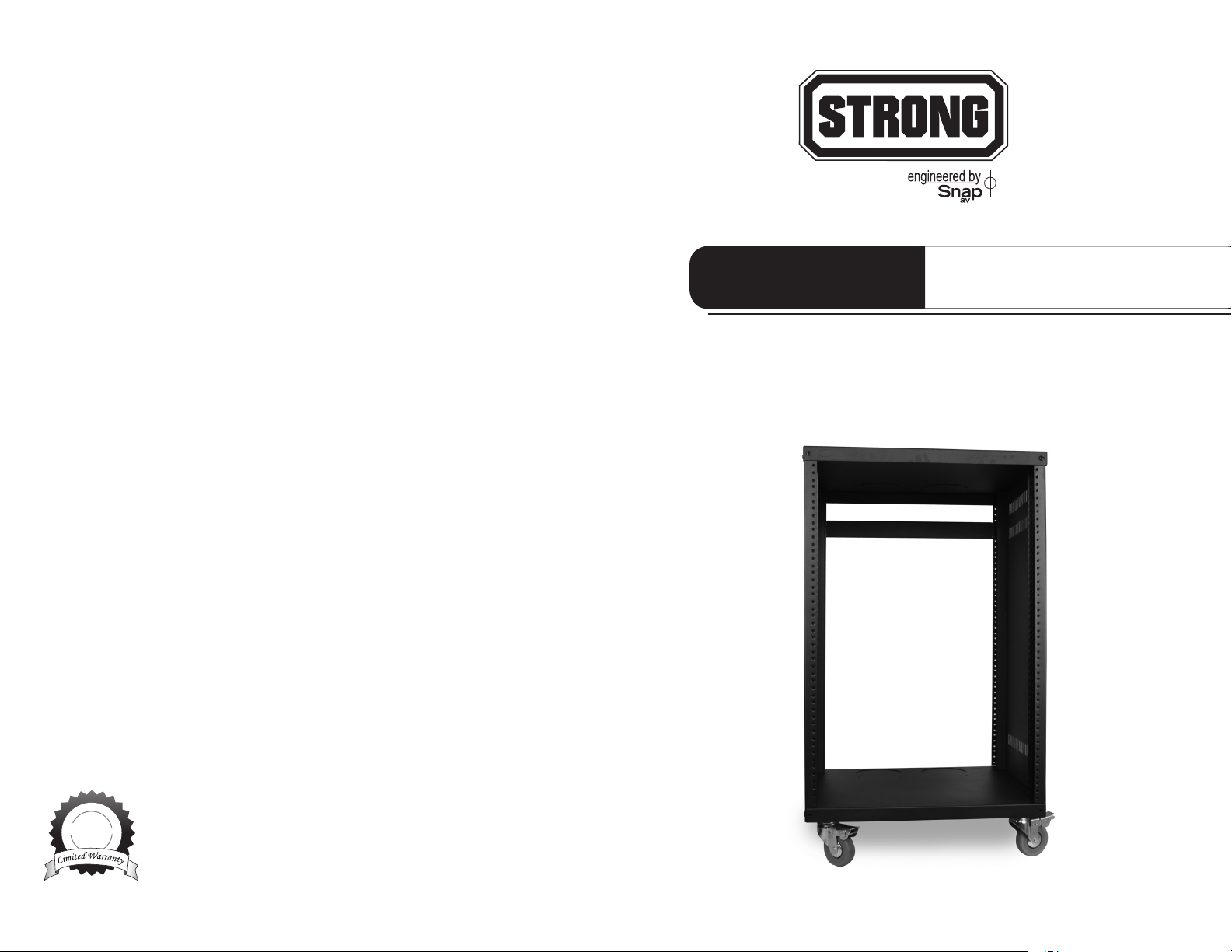
ASSEMBLY MANUAL
CONTRACTOR SERIES RACKS
SR-CS-RACK-12U SR-CS-RACK-16U SR-CS-RACK-21U
A vent should be placed above components that generate excessive heat,
such as surround receivers, amplifiers, satellite receivers, DVR’s, cable boxes
and media servers.
NEED RACK SCREWS?
Screws are not included with our rack accessories, but extra screws are
available (SR-SCREWS-200JAR). One no-roll jar includes 200 black 10/32
screws featuring #2 Phillips heads and captive nylon washers.
Lifetime Limited Warranty
All Strong™ products have a Lifetime Limited Warranty. This warranty includes
Lifetime
parts and labor repairs on all components found to be defective in material or
workmanship under normal conditions of use. This warranty shall not apply
to products which have been abused, modied or disassembled. Products to
be repaired under this warranty must be returned to SnapAV or a designated service
center with prior notication and an assigned return authorization number (RA).
For Techincal Support : 1.866.838.5052
120309-1419
Page 2
Strong™ CONTRACTOR SERIES RACKS
Strong™ equipment racks are solid steel and feature fully enclosed
steel side panels. They are available in three sizes: 12-space, 16-space
and 21-space. The racks are set upon 4 heavy-duty, 3-inch (75 mm) rubber
casters with locking fronts. Each equipment rack includes a 1U blank panel
for support on the back side of rack. The unique front and back pillar
construction allows the racks to be assembled to accept either Metric
or English Standard thread sizes. The inside of each pillar has a removable
sticker which points to the corresponding thread pattern - Metric (to use
M6 rack screws) or English Standard (to use 10/32 rack screws).
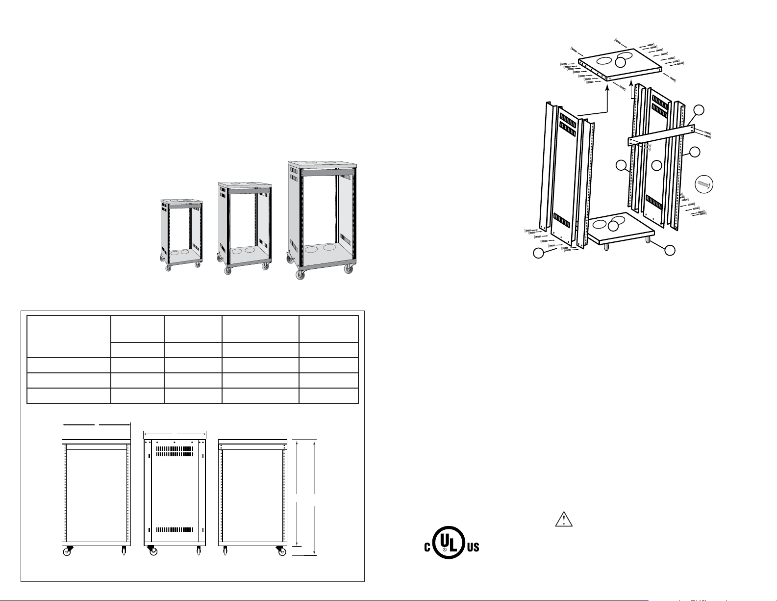
RACK SIZE OPTIONS
Equipment racks are
available in three sizes:
• 12 space
• 16 space
• 21 space.
PARTS INCLUDED
1. Top Plate
2. Side Plate
3. Front Pillar
4. Back Pillar
5. Base Plate
6. Casters (4)
7. Rack Assembly Screws
8. 1U Blank Plate
1
8
4
3
5
7
2
6
MODEL
SR-CS-RACK-12U
DEPTH RACKING
HEIGHT
SR-CS-RACK-16U
W/ CASTERS
HEIGHT
SR-CS-RACK-21U
WIDTH
“A” “B” “C” “D”
SR-CS-RACK-12U 18.11” 23.62” 27.55” 19.96”
SR-CS-RACK-16U 18.11” 30.70” 34.65” 19.96”
SR-CS-RACK-21U 18.11” 39.37” 43.31” 19.96”
D
FRONT VIEW SIDE VIEW
A
C
B
w/CASTERS
REAR VIEW
RACK ASSEMBLY
Lock the casters before starting assembly.
• First ensure that the four pillars are arranged with threaded screw
holes facing outwards.
Note: Sticker on inside of each pillar points to the location
of Metric and English Standard thread pattern.
With the base plate (part #5) flat on the ground, use three of the
supplied rack assembly screws (part #7) to attach each side plate (
part #2) so that the inner flange is flat against the base plate.
• On either side of each side plate, screw in the bottom of the pillars
using two rack assembly screws (part #7) per pillar (parts #3 and #4)
with the inner flange sitting flat against the base. One side of the
threaded screw holes in each pillar should be facing outwards,
either Metric or English Standard.
• Place the top plate (part #1) over the sides of the rack so that the four
pillars and side plates fit inside the top plate and attach using eighteen
supplied rack assembly screws. For extra stability, install 1U Blank Plate
(part #8) to upper most position on back side of the rack.
CAUTION:
This rack is intended for use only with shelf models
SR-SHELF-2U,-3U,-4U, and -5U with a maximum combined
load of 600 pounds. Use with heavier than the maximum
load indicated may result in instability causing possible injury.
 Loading...