

Page 1

3. Insert the metal bushings into the top and bottom
of the lower pole (see illustration 3a) and attach
the back plate to the lower pole using the supplied
Hex Bolt, Washers and Nut (See illustration 3b)
with 17mm socket. NOTE: Backplate tilt adjusting
levers are oriented on the top.
4. Attach the Mount Arms to your Display using
the bolts provided with your display or the
appropriate hardware from hardware kits 1-5.
Use a lock washer (C, F, I, or L) and M6 Washer (O)
if needed. Spacers (M,N) should only be used
for displays with curved backs or recessed
3b
mounting holes.
5. Using help of another person, hook the
display with the mounting arms attached
onto the lower portion of the mount.
IMPORTANT: Using a Philips head
Screwdriver, tighten the security screws
on the bottom of the arms to make sure
the display is
not accidentally
5
A, B, D, E, G, H, J, or K
knocked from
the mount.
3a
C, E, I, or L
F
SM-CM-T-L
Universal Ceiling Mount
4
M or N
O
Security Screws
6. To set the tilt, have one person hold the display
rmly while another loosens the tilt adjustment
levers (see illustration 6). Move the display to the
desired tilt angle and retighten the adjustment
ratchet levers. Cables may be routed through the
drop down pole of the mount.
Lifetime Limited Warranty
Lifetime
Strong™ Mounts have a Lifetime Limited Warranty. This warranty includes parts and labor repairs on all components
found to be defective in material or workmanship under normal conditions of use. This warranty shall not apply to products which have been abused, modied or disassembled. Products to be repaired under this warranty must be returned
to SnapAV or a designated service center with prior notication and an assigned return authorization number (RA).
For Technical Support call 1.866.838.5052
Tilt Adjustment
Knobs
6
090819
Page 2
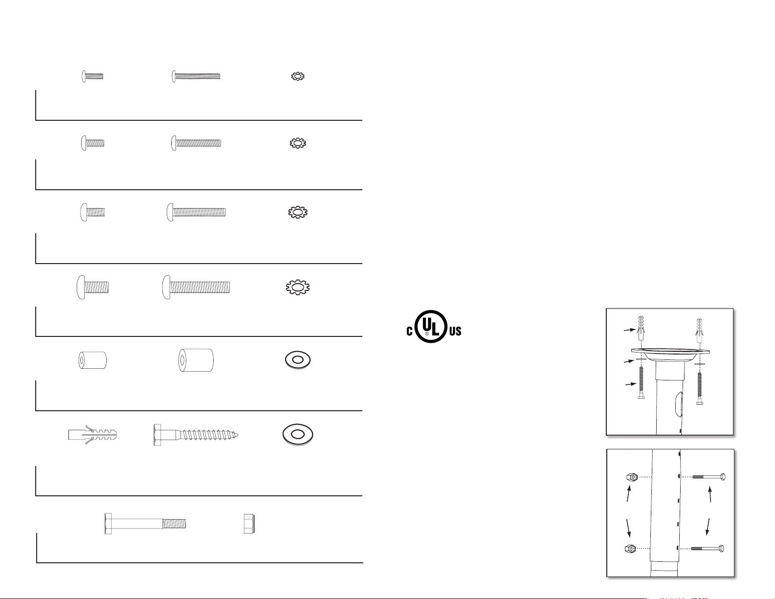
HARDWARE KIT
WARNINGS
• These instructions must be read and understood prior to attempting
installation. Professional installation or assistance is recommended.
Pkg 1
(A) M4x12 Bolt (x4) (B) M4x30 Bolt (x4) (C) M4 Lock Washer (x4)
Pkg 2
(D) M5x12 Bolt (x4) (E) M5x30 Bolt (x4) (F) M5 Lock Washer (x4)
Pkg 3
(G) M6x12 Bolt (x4) (H) M6x35 Bolt (x4) (I) M6 Lock Washer (x4)
Pkg 4
(K) M8x40 Bolt (x4)(J) M8x16 Bolt (x4) (L) M8 Lock Washer (x4)
Pkg 5
(M) Small Spacer (x4) (N) Large Spacer (x4) (O) M6 Washer (x4)
Pkg 6
(P) Concrete
Anchor (x4)
(Q) M10x80
(Q) M8x63
Lag Bolt (x4)
(R) Lag Bolt
Washer (x4)
• This mount is intended for use only with a maximum weight of 165 lbs
(75 kg). Use with weights heavier than this may result in instability
causing possible injury.
• The mounting surface must be capable of supporting the combined weight
of the mount and the display.
• Safety gear and proper tools must be used. Failure to do so can result in
property damage and/or injury.
• A minimum of two people are required for this installation. Do not attempt
to install this mount alone under any circumstance.
• Follow all instructions and recommendations regarding adequate ventilation
and suitable locations for mounting your display. Consult the owner‘s manual
for your display for more information
TOOLS REQUIRED:
Ratchet; 13mm, 14mm, 17mm sockets; Philips Head Screwdriver; Power Drill;
& 3/16 drill bit.
CAUTION: This wall mount
is intended for use only
with the maximum weight
of 165 lbs
P
R
INSTALLATION INSTRUCTIONS
Q
1. Pre-Drill holes for Lag Bolts in ceiling
using 3/16 drill bit. Attach the upper
portion of the mount to the ceiling
using (4) four Lag Bolts (Q) and (4)
Lag Bolt Washers (R). Use the
Concrete Anchors only if you are
installing the mount to a
Concrete Ceiling.
1
Pkg 7
(S) Hex Bolt (x2) (T) Nylock Nut (x2)
2. Insert the lower portion of the mount into
the upper tube and adjust to the desired
height. Secure the poles together using
(2) Hex bolts (S) and (2) Nylock nuts (T)
supplied. (2) Bolts and Nuts must be
used at all times.
T
S
2
 Loading...