

Page 1
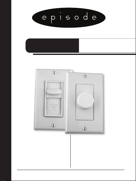
OWNER’S MANUAL >>VOLUME CONTROL
EVC-100R, EVC-100S
INTRODUCTION & PRE CONSTRUCTION
2
WIRING/SETTING THE IMPEDANCE
3
EXAMPLE/INSTALLATION & WIRING
4/5/6
DIAGRAM
7
SPECIFICATIONS
8
Page 2

CONGRATULATIONS ON SELECTING AN EPISODE™ VOLUME CONTROL.
Episode is one of the most highly-regarded brands of electronics
and speakers available today. We appreciate your business and
we stand committed to providing our customers with the highest
degree of quality and service in the industry.
The Episode EVC-100R and EVC-100S are 12-step stereo volume
controls that feature selectable impedance-match settings of 1X,
2X, 4X, and 8X. This allows you to connect multiple speakers to
an amplier without overloading the amplier.
PRE-CONSTRUCTION
Both the EVC-100R and the EVC-100S t easily into the majority
of 18 cubic inch single-gang boxes and rings available today. If
local building code allows, use of a ring provides for the easiest
installation as the full depth of the wall is accessible. Some building
codes allow low voltage devices such as volume controls to be
enclosed in the same electrical boxes as 110 volt devices. Episode
does not recommend this type of installation as interference may
be introduced to the audio signal. For the same reason, take care
not to install volume controls next to high wattage light dimmers.
2
Page 3

WIRING
The EVC-100R and the EVC-100S can accommodate 14 to 22gauge speaker wire. The longer your run, the thicker the wire should
be. All in-wall and in-ceiling wire installations are subject to local
code re ratings. Never use lamp or zip cord for an installation where
the wire will be in a wall or ceiling. Always use multi-strand copper
speaker wire for your installations. UV protected wire should be
used for outdoor installations.
• Check your local building and re rating codes for low voltage device
installation & wiring requirements before you begin your installation.
• In existing construction installations, check for obstructions
such as any pipes, conduit or wiring before cutting into drywall.
SETTING THE IMPEDANCE SWITCH
A single switch on the EVC-100R and the EVC-100S changes the
impedance setting of the volume control. Three factors determine
the correct setting:
1) The minimum impedance rating of the amplier being used.
2) The number of speakers being connected to the amplier channel.
3) The impedance of the speakers being connected to the amplifier channel.
Carefully determine the system impedance. Once that is done, the switch
settings for the volume control are easy to make.
Two simple equations will determine the system impedance:
1) Impedance Rating of Speakers divided by the number of speakers
connected to channel = System Impedance
Is/N=It
2) Ampliers Minimum Impedance Rating / by System Impedance
= Impedance Match Switch Setting
Im/It=X.
3
Page 4

EXAMPLE
If the amplier’s minimum impedance rating = 8 ohms and you wish
to connect four 8 ohm speakers to a single amplier channel:
8 ohm speakers / by 4 speakers = 2 ohm system impedance
8 ohm amplier / by 2 ohm system impedance = 4X switch setting
Most speakers are rated at 4, 6 or 8 ohms. If connecting speakers
of different impedances to an amplier, an average impedance
must be determined; 6-ohm speakers should be entered into
the equation as 4-ohm speakers. All volume controls connected
to the amplier should always have the same impedance match
setting. Never go below an amplier’s minimum impedance rating
as this can cause damage to the amplier. Both the EVC-100R and
EVC-100S have minimum impedance ratings of 4 ohms. If
connecting more than one speaker to the EVC-100R or EVC-100S,
make sure not to exceed this minimum.
INSTALLATION AND WIRING
The removable connectors allow for easy termination of speaker
wire to the volume controls.
1. Strip back 1/4” of insulation from each wire that is to be
connected to the volume control. Twist the exposed conductors
tightly so that there are no stray strands.
2. To make connecting wires to the volume control quick and easy, your
Episode volume controls use connectors that allow wire connection
without the need for additional tools such as screwdrivers. Simply
ip the levers on each connector up before inserting the
appropriate wire. Insert the wires then snap the levers down.
4
Page 5

The spring-loaded mechanism will hold the wires in place.
3. Connect the wires going to each speaker to the connector labeled
SPEAKERS. Make sure to maintain proper polarity.
4. Check that the amplier or receiver being used is turned off and
then connect the wire coming from the amplier to the connector
labeled AMPLIFIER.
5. Once all conductors are inserted in to the connectors, visually
inspect each of your connections to ensure that there are no
stray strands that might short and that there is not an excessive
amount of exposed wire outside of the connector. Also be
sure that the connector is tightened down on bare wire and not
insulation. Install the connectors back on to the volume control
circuit board. Please be sure that the connectors are in the
correct place on the volume control.
REVERSING THE AMPLIFIER & SPEAKER CONNECTORS
WILL LIKELY CAUSE DAMAGE TO THE AMPLIFIER, VOLUME
CONTROL AND THE SPEAKERS AND IS NOT COVERED
UNDER WARRANTY.
6. An optional step is to change the color of the trim plate on
the face of the volume control. This is done easily by pressing
on the two tabs (only one tab for slider volume control) of the
plate on one end of the volume control and pushing towards
the knob shaft or slider lever. Rotate out the plate and replace
with the color of your choice.Your volume control is supplied
with white parts installed and almond parts included for an easy
and fast change. These are available for both the knob and
slider style volume controls. When the plate change is complete,
push the knob into place. When installing the slider plate, be
sure to align the slider knob with the slider mechanism.
5
Page 6

7. Install the volume control in the box or ring using the two longer
screws provided. Be careful not to force the volume control into
the ring or box as this will cause the connectors to become
loose or may result in wires being forced out of the connectors.
8. Place Decora plate over volume control. Insert and tighten short
color-matched screws until the cover is tight and ush with the wall.
DO NOT CONNECT THE WIRES FROM THE AMPLIFIER TO THE
VOLUME CONTROL UNTIL YOU HAVE CHECKED THE FOLLOWING:
• Measure the resistance between the + and – of each pair of
wires that is to be connected to the amplier’s speakers outputs
using an Ohm Meter. Under no circumstances should this value
be below 3.5 Ohms. A reading of less than 3.5 Ohms may mean
that the wiring input and output connectors on the volume
control have been reversed. An open reading likely indicates a
polarity reversal.
• Conrm that the amplier is powered down before connecting
any volume control wires to it.
6
Page 7

Impedance
switch
To amplier
L+ L- R- R+
EVC-100R
EVC-100S
L+ L- R- R+
To speakers
L+ L- R- R+
8X
4X
2X
1X
L+ L- R- R+
To amplier
Impedance
switch
To speakers
7
Page 8

SPECIFICATIONS
Power Rating 100 Watts continuous or 200 Watts Peak Music Power per channel
Frequency Response 20 - 20KHz, +/- 0.5 dB into 8 ohms
Total Harmonic Distortion <1%
Impedance Settings 1x, 2x, 4x, 8x
Speaker Load Impedances 4, 6, or 8 ohms
Dynamic Range 54 db
Lifetime Limited Warranty
All Episode Volume Controls have a Lifetime Limited Warranty. This warranty includes
parts and labor repairs on all components found to be defective in material or workmanship under normal conditions of use. This warranty shall not apply to products which
have been abused, modied or disassembled. Products to be repaired under this warranty must be returned to the SnapAV or a designated service center with prior notication and an assigned return authorization number (RA).
Episode
10405-A Granite Street
Charlotte, NC 28273
1-866-424-4489
Tech Support:
1-866-424-4489
email: techsupport@snapav.com
www.snapav.com
©2007 Snap AV • Charlotte, NC
 Loading...