

Page 1
OWNER’S MANUAL
Episode® Commercial 250 Series
6 ½" In Ceiling Speaker
WELCOME TO EPISODE
Thank you for purchasing a great product from one
of the best sounding speaker lines available today,
Episode®. We appreciate your purchase and are
committed to providing the highest quality products
possible.
The Episode® Commercial Series In-Ceiling models
are a superb choice for almost every type of
commercial speaker installation. They have been
designed to meet the needs of commercial audio
installation specialists everywhere.
The ECS-250-IC-6 is an ideal solution for 70v systems where a more aesthetically pleasing “residential” speaker
look is required, or whenever ceiling space limits the installation of a larger backcan loudspeaker model. It can be
installed in either drywall or into an acoustic ceiling tile system.
®
IMPORTANT INSTRUCTIONS AND CONSIDERATIONS FOR INSTALLATION
• Read and follow all instructions.
• Before beginning installation, carefully plan locations accounting for potential electrical, plumbing or
other obstacles.
• Contact a suitable contractor if you are unsure of how to best install.
GENERAL GUIDELINES
• Keep speakers approximately 2 feet away from corners and other surfaces that might interfere with or
reect sound, such as tall furniture.
• For rooms less than 300 square feet, two speakers should sufce. The further apart they are, the better the
sound will be. Keep the distance at a maximum of 8-10 feet to avoid a “hole” in the middle.
• For rooms larger than 300 square feet, use 3 or more speakers. Stagger them across the space for ideal
sound dispersion.
PG.1
Page 2
INSTALLATION PREPARATION
New Construction
Episode® speaker installations can be simplied by using Episode® new construction brackets (sold
separately). These are installed prior to drywall, and allow for precise placement to ease the nal installation of
the speaker.
EXISTING CONSTRUCTION
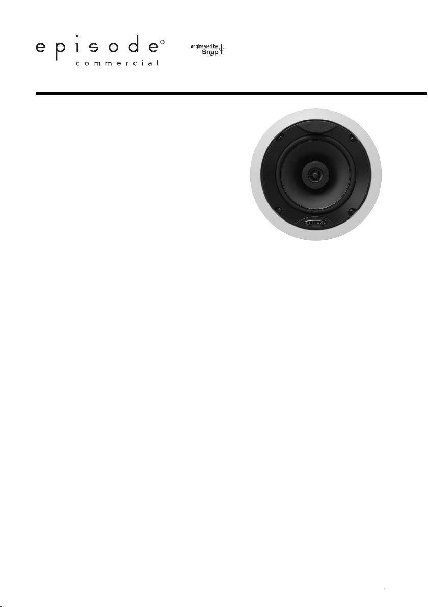
1. Choose a location for each speaker that is free of obstructions created by joists, HVAC ductwork, electrical
wire runs, plumbing or anything else that might not allow for the depth of the speaker or create interference
or noise.
2. Once you have determined your locations, mark the hole to cut out for the speaker using the supplied
template. Don’t forget to allow for the size of the speaker bezel if you are choosing to install the speaker
near a side wall or other item that could become an obstacle.
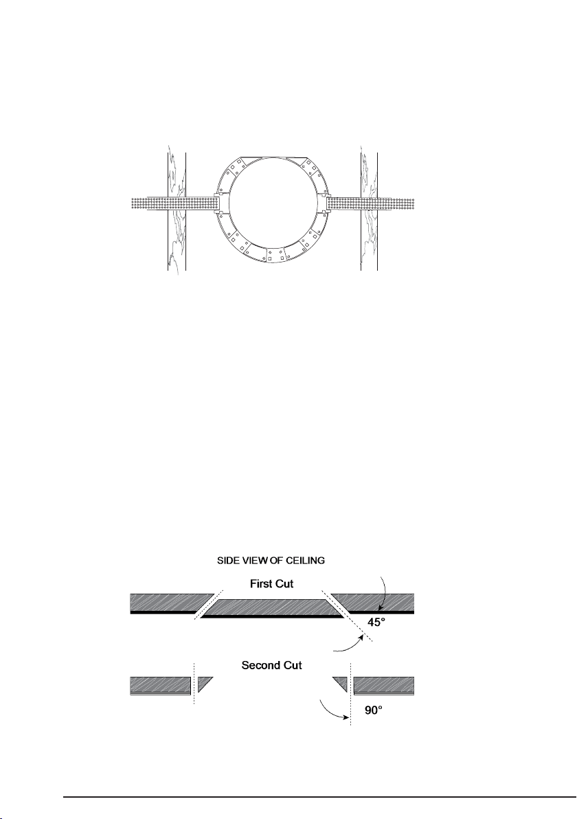
3. If you are unsure of potential obstacles, carefully cut your holes using an angle to the inside of the
cutout area as illustrated. This will allow you to ‘plug’ the hole easily if needed. If the area is clear and a
good location for the speaker, cut the edges of the opening at 90 degrees to accommodate the speaker
diameter.
PG.2
Page 3

CONNECTING AND MOUNTING
1. Using wire nuts, connect the common (GND) from the amplier to the Black lead on the transformer.
2. Using wire nuts, connect the Positive lead to the Colored lead appropriate for the desired
wattage as listed below.
Black
Red
Yellow
Green
Blue
Common (GND)
.5 Watts
1 Watt
2 Watts
4 Watts
Black Common (GND)
Red .5 Watts
Yellow 1 Watt
Green 2 Watts
Blue 4 Watts
1. Insert the speaker into the ceiling and tighten each of the four screws for the speakers ‘dog’ legs
enough to clamp the speaker against the ceiling.
2. Insert the speaker grille by pressing gently around the edges. The grille is designed for a tight
t but will still install easily. Do not force or bend the grille as this could affect the nal t and
appearance.
SPECIFICATIONS
Color 70 Volt
WOOFER: 6½” TREATED PAPER CONE, NOMEX SPIDER & HIGH TEMP
TWEETER: 1/2” FABRIC DOMES, NEODYMIUM MOTOR,
POWER HANDLING: 50 WATTS RMS, 125 WATT PEAK
FREQUENCY RESPONSE(-6DB): 58HZ - 20KHZ
SENSITIVITY -2.83 V / 1 METER: 87 DB
CROSSOVER FREQUENCY: 4.3 KHZ
WEIGHT: 2.1 LBS. EACH
GRILL TYPE: POWDER COATED PERFORATED GRILL
CUTOUT DIMENSIONS: 7.7" DIAMETER
MOUNTING DEPTH: 2.25"
FINISHED DIMENSIONS: 8.1/2" DIAMETER, 3 3/8" D
VOICE COIL
FERROFLUID COOLED
© 2012 Episode
PG.3
Page 4

PAINTING
It is highly recommended that the speakers be painted prior to installation. If it is necessary to paint them
while installed, the provided paint mask should be used in place of the grille to protect the speaker. The grille
may be painted as well with great care taken not to clog the ne holes with paint. Only paint grilles when
they have been removed from the speakers.
TROUBLESHOOTING
Troubleshooting
Episode® Speakers are designed to function trouble-free. Most problems that occur are due to simple issues.
If you have trouble, please check the list of simple xes below. If the problem persists, contact Episode
Customer Service at 1.866.838.5052
No Sound
• Verify that there is audio coming from the source selected. Select another source if necessary.
• Ensure that the audio source is turned on and connected properly.
WARRANTY
Limited Lifetime Warranty
Episode in-wall, in-ceiling and bookshelf Speakers have a Lifetime Limited Warranty. This warranty
includes parts and labor repairs on all components found to be defective in material or workmanship under
normal conditions of use. This warranty shall not apply to products which have been abused, modied or
disassembled. Products to be repaired under this warranty must be returned to SnapAV or a designated
service center with prior notication and an assigned return authorization number (RA).
CONTACTING TECHNICAL SUPPORT
Phone: (866) 838-5052
Email: Techsupport@snapav.com
PG.4
© 2012 Episode
120730-1600
®
 Loading...