

Page 1
OWNER’S MANUAL >>
EA-AMP-SUB-1D-500
SUBWOOFER
AMPLIFIER
Page 2
IMPORTANT SAFETY INSTRUCTIONS
IMPORTANT SAFETY INSTRUCTIONS
IMPORTANT SAFETY INSTRUCTIONS
WARNING: To reduce the risk of re or electric shock, do not expose this apparatus in or near rain or moisture.
1. Read and keep these instructions for future reference.
2. Do not use this apparatus near water.
3. Clean only with a dry cloth.
4. Do not block any ventilation openings. Install according to manufacturer’s instructions.
5. Do not install near any heat sources such as radiators, heat registers, stoves or other apparatus
(including ampliers) that produce heat.
6. Do not override the safety purpose of the polarized or grounding-type plug. A polarized plug has two blades -
one wider than the other. A grounding type plug has two blades and a third grounding prong. The wide blade
or the third prong is provided for your safety. If the provided plug does not t into your outlet, consult an
electrician for replacement of the obsolete outlet.
7. Protect the power cord from being walked on or pinched particularly at plug, convenience receptacles, and
the point where it exits from the apparatus.
8. Only use attachments/accessories specied by the manufacturer.
9. Use only with a cart, stand, tripod, bracket or table specied by the manufacturer,
or sold with the apparatus. When a cart is used, use caution when moving the
cart/apparatus combination to avoid injury from tip-over.
10. Unplug this apparatus during lightning storms or when unused for long periods of time.
11. Refer all servicing to qualied service personnel. Servicing is required when the apparatus has been damaged
in any way, such as when the power-supply cord or plug is damaged, liquid has been spilled or objects have fallen
into the apparatus, the apparatus has been exposed to rain or moisture, does not operate normally, or has
been dropped.
12. To completely disconnect this equipment from the AC mains, disconnect the power supply cord plug from
the AC receptacle
13. This is CLASS II apparatus with double insulation, and no protective earth provided.
The lightning ash with arrowhead symbol, within an equilateral
CAUTION
CAUTION: TO REDUCE THE RISK
OF ELECTRICAL SHOCK, DO
NOT REMOVE COVER. NO USER
SERVICEABLE PARTS INSIDE.
REFER SERVICING TO QUALIFIED
SERVICE PERSONNEL.
triangle, is intended to alert the user to the presence of
uninsulated dangerous voltage within the product’s enclosure
that may be of sufcient magnitude to constitute a risk of electric
shock to persons.
The exclamation point within an equivalent triangle is intended
to alert the user to the presence of important operating
and maintenance (servicing) instructions in the literature
accompanying the appliance.
2
Page 3
WELCOME TO EPISODE
Episode® is one of the most highly regarded brands in audio available today. We stand committed to providing our
customers with the highest degree of quality and service in the industry.
The Episode® EA-AMP-SUB-1D-500 Subwoofer Amplier is a superb choice for a variety of subwoofer applications
and is designed to work with almost every type of home theater or audio system. It has been designed with advanced
technological components that produce astounding sound effects in movies, as well as recreating the heights and
depths of all types of music. Episode® ampliers provide the best value and quality possible for your home
theater needs.
This Digital Subwoofer Amplier can be installed in cabinetry, on an equipment shelf, or rack-mounted into
a standard 19˝ Equipment Rack, utilizing a sleek 1U design to minimize space requirements. EQ settings,
Volume, and Power can be controlled using the supplied hand-held IR remote. The EA-AMP-SUB-1D-500
has two EQ mode settings: Music or Movie. Frequency, phase, and boundary adjustments offer customized
bass management. The included remote can be downloaded into learning remotes. User controls are also
located on the front panel. The Front Panel of the Amplier has an IR Receiver. There is a second
hard-wired IR jack on the back of the unit. The Class D design keeps the amplier running cool while
providing ample power for the ES-SUB-IW-DUAL8. The low impedance drive capabilities offer massive
headroom and allow for multiple ES-SUB-IW-DUAL8 connections. Two subwoofer output connections
simplify wiring to multiple subwoofer locations. Built for today’s sophisticated home theater LFE signals,
the EA-AMP-SUB-1D-500 protects the speaker from clipping.
3
Page 4

1 2 3 4
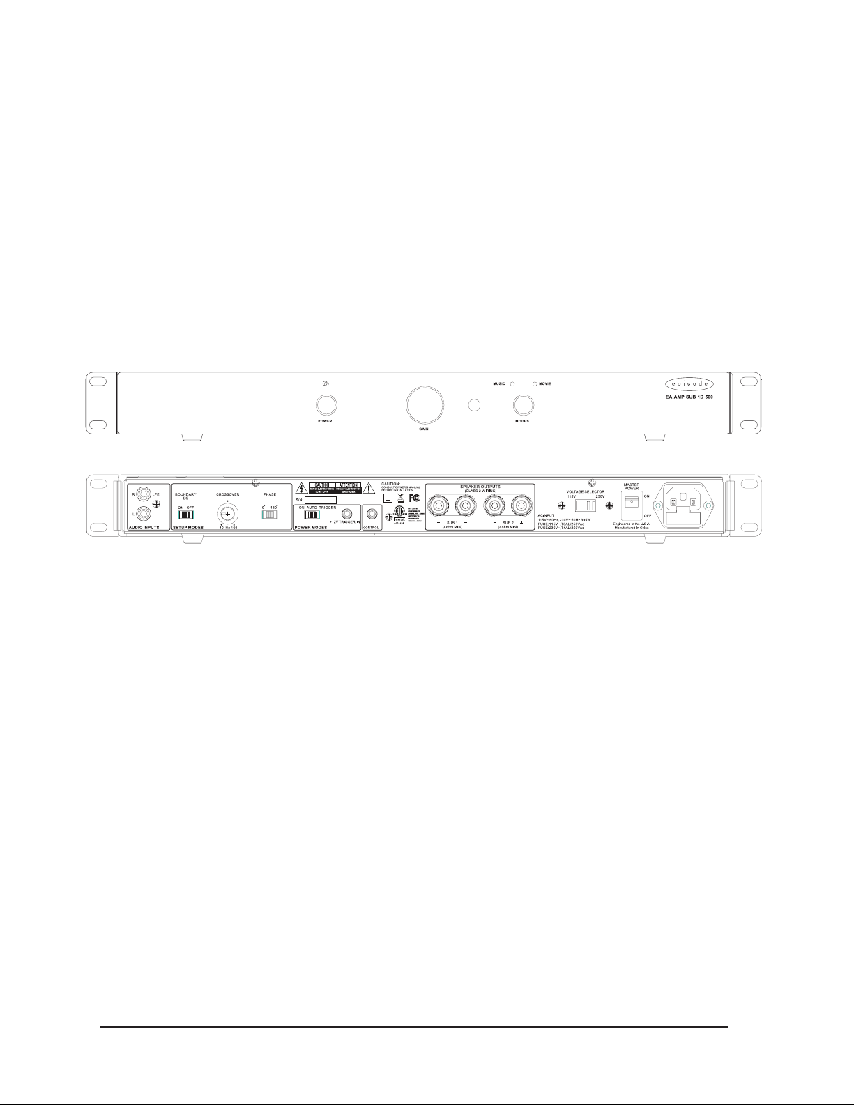
REAR PANEL FEATURES
1. AUDIO INPUTS
a. Connect to Unbalanced Female RCA Inputs.
b. Connect to the Right Female RCA input from a LFE output connection on a receiver or pre-amp processor.
NOTE: If not using an LFE connection, both inputs have been calibrated to the same sensitivity level and
should be connected. When connecting to a stereo pre-amp connection, use a Y-Adapter when connecting
2. SETUP MODES
a. BOUNDARY EQ – Select the appropriate setting based on these guidelines below.
b. PHASE – Factory-set at 0°, adjustable to 180°. The phase of the subwoofer can be adjusted to ne tune
the signal coincidence of the subwoofer and the lower frequencies of your speakers. Adjust the phase, listening
for an increase in mid bass in the crossover region.
c. CROSS-OVER – Crossover frequency setting of the Low Pass Filter. Factory-set at 80Hz.
Each EA-AMP-SUB-1D-500 has the capability to be adjusted from 40 to 160Hz.
d. Boundary EQ – Removes exaggerated boomy sounds created by corner loading, large wall surfaces,
or installations inside custom cabinetry. For a natural, tighter performance in less than ideal installation
circumstances where boundaries are inuencing the sound desired, select the ON position to compensate.
For all other installations, or for when the exaggerated boomy sound is desired, leave the boundary switch
in the OFF position.
3. POWER MODES
a. ON – Always On
b. AUTO – On, triggered via signal sense; when signal is off, amp will stay on for approximately
15 to 20 minutes.
c. TRIGGERED – On, triggered by 12 VDC, 100mA minimum. NOTE – Use the 1/8˝ mono mini-jack to connect
a 12 volt trigger wire from other devices. Connector polarity is tip positive.
4
Page 5

5 6
4. CONTROL INPUT
a. Use this 1/8˝ Mono mini-jack to connect to most IR emitter output connections. The signal will be transferred
and ashed to the IR receiver internally behind the front panel. This will eliminate the need to add “stick-on”
emitters in most systems. NOTE: Due to variations in IR system types, not all are compatible with this control
jack. In some cases, an emitter will be needed to place over the front panel IR window.
5. SPEAKER OUTPUTS
a. Connect the speaker wires to the Binding Posts.
NOTE: Red is Positive and Black is Negative.
Bridged output, do not ground.
b. Use either Bare Speaker Wire or Banana Plugs to terminate the speaker wire.
6. AC POWER
a. Master Power ON/OFF power switch for the amplier.
b. Input voltage setting selects the appropriate 115V or 230V setting.
c. IEC Power Cord
5
Page 6

INSTALLATION – FIRST STEPS
POSITIONING YOUR EPISODE AMPLIFIER
Episode ampliers are designed to help deliver a great audio experience
that makes your music come alive for years to come. However, where you
place the amplier can have a large effect on the performance that you receive
and the life of the unit. If you are not rack-mounting the amplier, position it
with all feet resting on a solid level surface. Be sure that the amplier is in a
well-ventilated area that provides adequate cooling. If your installation lacks
good air ow, such as some solid door cabinets or wall-mounted racks, it may
be necessary to create some ventilation to air outside the cabinet or rack.
VENTILATION
Do not block ventilation holes, or impede air ow by placing objects on or
around the amplier. Do not place the amplier on carpeting or any similar
material. Do not install the amplier near a source of heat, or in an
extremely humid or wet location.
Make sure that there is a minimum of 5”
of free air space above the amplier and
3” on each side for proper ventilation.
INSTALLATION – GETTING CONNECTED
CAUTION:
amplier’s power switch positioned to ‘Off’. Connect the power cord last
to be sure that the amplier is off during all of your connections and set up.
All connections and switching must be done with the
Allow a minimum of 2” of depth behind unit
to accommodate cables and connectors.
Standard Placement of Amplier in Cabinet
INPUTS
For line level connections, use high quality RCA cables that feature low impedance, shielding and high quality connectors.
SPEAKER OUTPUTS
Use 14-18 gauge stranded two-conductor loudspeaker wire for all high level connections. At each loudspeaker-level
connection, ensure that at least 2 inches of each conductor are separated. Strip away 1/4 inch of insulation from each
conductor. Connect the appropriate conductor to each screw terminal, observing correct polarity.
RACKMOUNT INSTALLATION
1. Remove the amplier’s four feet from the bottom of the chassis.
2. Attach the included rack-mount ears to the front sides of the amplier chassis.
3. Securely mount the amplier into the 19” equipment rack. The amplier will
occupy 1U of rack space.
4. Even though the amplier produces very little heat, it is always wise to leave
ventilation between components.
6
Page 7

REMOTE CONTROL
The remote control has the following functions:
1. POWER - Toggles between Standby Mode and ON.
2. VOL+/- – Adjusts the volume.
3. MUTE – Mutes the subwoofer. Press again to unmute.
4. MUSIC/MOVIE – Selects the corresponding EQ mode.
OPERATION
The EA-AMP-SUB-1D-500 can be controlled manually from the front panel or via the supplied hand-held remote. A remote IR input can also
be used for systems hidden behind closed cabinet doors or in an equipment rack located in other areas of the home. On the front panel,
you will nd the following features:
1. Master Volume Control – The master volume knob is a continuous rotary control. To adjust volume, use the gain adjustment on
the AV receiver or pre-amplier to make minor adjustments. Use a dB meter to measure the subwoofer output to the level suited
for the room and the listener.
2. Music or Movie quick EQ adjustments – The Music or Movie toggle button changes the EQ to an appropriate curve for the source
material. You can use the hand-held remote to change the curve between Music and Movie modes. The Music or Movie mode IR
codes can be inserted into IR learning macros to change the EQ per source. LEDs placed above the Music or Movie text on the front
panel indicate the EQ mode. Music mode is at; Movie is bumped 8dB between 30Hz and 80Hz for added impact.
HINTS
For single in-room subwoofer placement, room shape, size, and environment play a large role in the impact of a subwoofer’s perceived
output. Due to the bass waves that pass through the room, certain areas can be perceived to sound thin and lacking bass while others
sound boomy and unnatural. This often happens within a few feet, and can cause the main listening area to be an undesirable location.
If you are forced to symmetrically install the subwoofer box in the home theater, use the phase switch located on the back of
the amplier. The ideal placement for a single subwoofer is in the room location that receives the highest dB level from the audio source
(ex. CD player, AV receiver, etc.). This can be tested with a dB meter by measuring various spots in the room. Mark the highest-rated spots
with masking tape to determine the best location. Consider the best sound, aesthetics, and installation-ease when choosing location.
Dual subwoofer installations will cancel standing waves or “quiet” spots in the room, and often ensure the most even
distribution of bass in a theater. Most home theater rooms, even smaller ones, benet greatly from adding a second subwoofer.
The Episode™ subwoofer amplier was designed for multiple subwoofer connections. (Note: This is a single amp with two
paralleled connections for convenience.)
The boundary switch and phase switch can create hidden and unique placement options not found on ordinary subwoofer
ampliers.
CLEANING
Use a soft cloth or paper towel to clean the amplier.
7
Page 8

SPECIFICATIONS
Continuous Power Output 312 watts RMS at 8 ohms
500 watts RMS at 4 ohms
Input Sensitivity 200 mv for full output, 500 watts, with level control set to max.
Frequency Response 18 - 160 Hz
Distortion .04% THD+N 1W/2W 100 Hz
Auto On Sensitivity 3 mv
External Trigger Voltage 5 V - 20 V
EQ Modes Music: Flat
Movie: +8dB@40Hz (30-80Hz)
Boundary EQ ON = Flat
OFF = +3dB
Dimensions 17˝ W (18.9˝ including rack mounts)
1.7˝ H (1.9˝ including feet)
10.4˝ D (11.2˝ including speaker connections)
Weight 19.7 lbs.
Certication ETL Listed and tested under UL/EN60065 for US and Canada
TROUBLE SHOOTING
This amplier is designed to function trouble-free. Most problems that occur are due to simple issues.
If you have trouble, check the list of simple xes below. If the problem persists, contact your authorized
Episode dealer or Episode technical support at 866-838-5052.
• Power cable to the amplier is incorrectly connected or plugged
into an outlet that does not have power. Check connections and
verify power at the outlet.
• Audio cable to the source component is not connected properly,
connected to output or the cable is defective. Check connections
No audio output
Hum or buzzing
sound is heard
Amplier will
not turn on
or replace cable with one that has been veried as good.
• Amplier is in standby mode, and needs to be turned on “BLUE LED”.
• Check the connections of the speaker wire at both the speaker and amplier.
• The level adjustment is turned down. Turn it to the right slowly to
raise the volume.
• Check RCA input cables by removing them one at a time (powering
down the amplier before disconnecting) and check to see if a
connection or cable is to blame.
• The amplier must be plugged into a live outlet.
• The Power Switch on the front panel must be on.
• The Power Mode switch may be set to the wrong mode for your system.
WARRANTY
2-Year Limited Warranty
Episode™ Amplier Products have a 2-Year Limited Warranty. This warranty includes parts and labor repairs on all
components found to be defective in material or workmanship under normal conditions of use. This warranty shall
not apply to products which have been abused, modied or disassembled. Products to be repaired under this warranty
must be returned to the SnapAV or a designated service center with prior notication and an assigned return
authorization number (RA).
101216
 Loading...