

Page 1
OWNER’S MANUAL >>
EA-AMP-SUB-1D-110
SUBWOOFER
AMPLIFIER
WELCOME TO EPISODE
Episode® is one of the most highly regarded brands in audio available today. We stand committed to providing our
customers with the highest degree of quality and service in the industry.
The Episode® EA-AMP-SUB-1D-110 Subwoofer Amplier is a superb choice for a variety of subwoofer applications
and work well with almost every type of home theater or audio system. It has been designed with advanced technological
components that produce astounding sound effects in movies, as well as recreating the heights and depths of all types
of music. Episode® ampliers provide the best value and quality possible for your home theater needs.
Page 2
EA-AMP-SUB-1D-110 Installation and Users ManualEA-AMP-SUB-1D-110 Installation and Users Manual
IMPORTANT SAFETY INSTRUCTIONS
IMPORTANT SAFETY INSTRUCTIONS IMPORTANT SAFETY INSTRUCTIONS
WARNING: To reduce the risk of re or electric shock, do not expose this apparatus in or near rain or moisture.
1. Read and keep these instructions for future reference.
2. Do not use this apparatus near water.
3. Clean only with a dry cloth.
4. Do not block any ventilation openings. Install according to manufacturer’s instructions.
5. Do not install near any heat sources such as radiators, heat registers, stoves or other apparatus
(including ampliers) that produce heat.
6. Do not override the safety purpose of the polarized or grounding-type plug. A polarized plug has two blades -
one wider than the other. A grounding type plug has two blades and a third grounding prong. The wide blade
or the third prong is provided for your safety. If the provided plug does not t into your outlet, consult an
electrician for replacement of the obsolete outlet.
7. Protect the power cord from being walked on or pinched particularly at plug, convenience receptacles, and
the point where it exits from the apparatus.
8. Only use attachments/accessories specied by the manufacturer.
9. Use only with a cart, stand, tripod, bracket or table specied by the manufacturer,
or sold with the apparatus. When a cart is used, use caution when moving the
cart/apparatus combination to avoid injury from tip-over.
10. Unplug this apparatus during lightning storms or when unused for long periods of time.
11. Refer all servicing to qualied service personnel. Servicing is required when the apparatus has been damaged
in any way, such as when the power-supply cord or plug is damaged, liquid has been spilled or objects have fallen
into the apparatus, the apparatus has been exposed to rain or moisture, does not operate normally, or has
been dropped.
12. To completely disconnect this equipment from the AC mains, disconnect the power supply cord plug from
the AC receptacle
13. This is CLASS II apparatus with double insulation, and no protective earth provided.
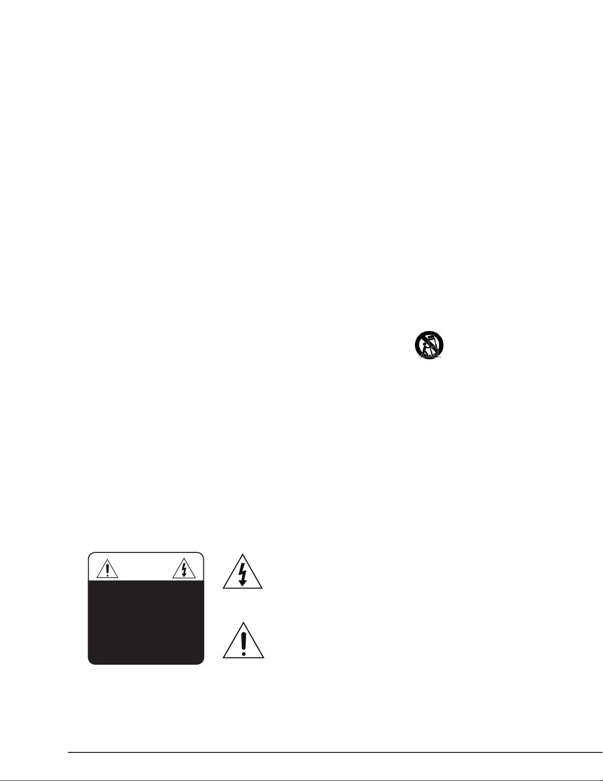
The lightning ash with arrowhead symbol, within an equilateral
CAUTION
CAUTION: TO REDUCE THE RISK
OF ELECTRICAL SHOCK, DO
NOT REMOVE COVER. NO USER
SERVICEABLE PARTS INSIDE.
REFER SERVICING TO QUALIFIED
SERVICE PERSONNEL.
triangle, is intended to alert the user to the presence of
uninsulated dangerous voltage within the product’s enclosure
that may be of sufcient magnitude to constitute a risk of electric
shock to persons.
The exclamation point within an equilateral triangle is intended
to alert the user to the presence of important operating
and maintenance (servicing) instructions in the literature
accompanying the appliance.
pg.2
Page 3
FEATURES
1 2
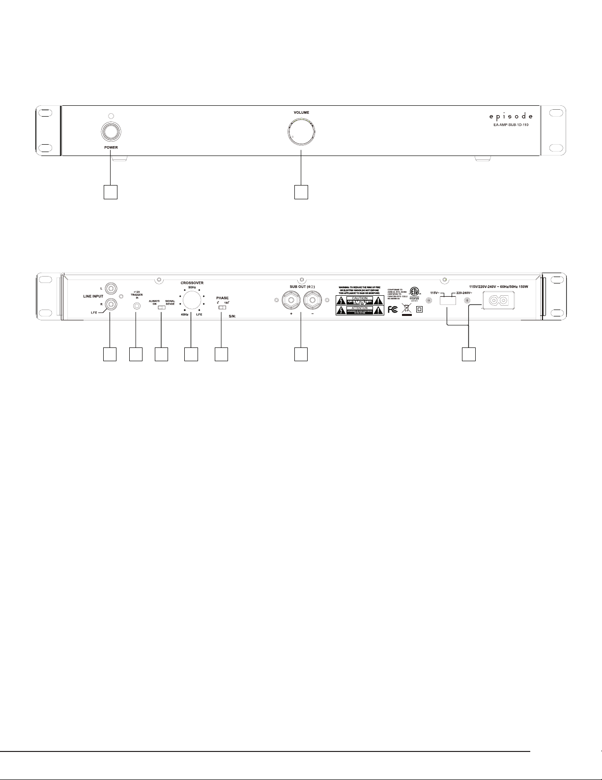
1. Power Switch
a. RED – Off/Standby
b. Blue – On/Operating
2. Output Volume Control
EA-AMP-SUB-1D-110 Installation and Users Manual
Engineered in the USA
Manufactured in China
2 3 4 5 6 71
1. AUDIO INPUTS
a. Connect the Right Female RCA input to an LFE output connection on a receiver or pre-amp processor.
b. Connect the Left and Right Female RCA input to the Left and Right front output. connections on a receiver or
pre-amp processor.
NOTE: Both inputs have been calibrated to the same sensitivity level. When using stereo pre-amp outputs, both connections should be
used to maintain proper input gain.
2. 12V Trigger In
a. Connect the 12V trigger output of the AV receiver to turn amp on when a 12V signal is received.
When using a 12V trigger, the Power Mode settings do not apply. See System Connections for more information.
3. POWER MODES
a. ON – Always On
b. Signal Sense – On, triggered via signal sense; when signal is off, amp will stay on for approximately 15 to 20 minutes.
4. CROSS-OVER
Crossover frequency setting of the Low Pass Filter can be adjusted from 40 to 140 Hz.
NOTE: When using the LFE input, set to LFE so the preamplier or receiver can control the crossover frequency.
5. PHASE
The phase of the subwoofer can be adjusted to ne tune the alignment of subwoofer signals and with those
from the main speakers. Adjust the phase, listening for an increase in mid bass in the crossover region.
6. SPEAKER OUTPUTS
a. Connect the speaker wires to the Binding Posts. NOTE: Red is Positive and Black is Negative.
Bridged output, do not ground.
b. Use Bare Speaker Wire, Spade Lugs, or Banana Plugs to terminate the speaker wire.
7. AC POWER
a. Input voltage setting selects the appropriate 115V or 230V setting.
b. IEC Power Cord
© 2011 Episode
pg.3
Page 4

EA-AMP-SUB-1D-110 Installation and Users ManualEA-AMP-SUB-1D-110 Installation and Users Manual
INSTALLATION – FIRST STEPS
POSITIONING YOUR EPISODE AMPLIFIER
Episode ampliers are designed to help deliver a great audio experience that makes your music come alive for years to come.
However, where you place the amplier can have a large effect on the performance that you receive and the life of the unit.
• Be sure that the unit is in a well-ventilated area that provides adequate cooling.
• Do not block the cooling vents located on both sides of the unit.
• Do not place the unit on carpeting or any similar material.
• Do not install the unit near a source of heat, or in an extremely humid or wet location.
• If your installation lacks good air ow (such as solid cabinet doors or wall-mounted racks), it may be necessary to
create ventilation to allow outside air into the space.
• Allow a minimum of 5” of free air space above the unit.
• Allow a minimum of 3” of free air space on either side of the unit. (Does not apply to rack mounting)
Minimum of 5" of fr ee air space above.
3"
Allow a minimum of 2” of depth behind unit to accommodate cables and connectors
When placing on a cabinet shelf, position the unit with all feet resting on a solid level surface.
5"
VENTILATION
Do not block ventilation holes, or impede air ow by placing objects on or
around the amplier. Do not place the amplier on carpeting or any similar
material. Do not install the amplier near a source of heat, or in an
extremely humid or wet location.
RACKMOUNT INSTALLATION
1. Remove the amplier’s four feet from the bottom of the chassis.
2. Attach the included rack-mount ears to the front sides of the amplier chassis.
3. Securely mount the amplier into the 19” equipment rack. The amplier will
occupy 1U of rack space.
4. Even though the amplier produces very little heat, it is always wise to leave
ventilation between components.
Minimum of 3" free air space
on each side.
Minimumof2”of depthbehind
unit to accommodate cables
and connectors.
3"
2"
pg.4
Page 5

EA-AMP-SUB-1D-110 Installation and Users Manual
SYSTEM CONNECTIONS
CAUTION: All connections and switching must be done with the amplier’s power switch positioned to ‘Off’ (LED will be
RED). Connect the power cord last to be sure that the amplier is off during all of your connections and set up.
AV Receiver
RS
CEN
R
Le & Right
Preamp Out
or
LFE Sub Out
+12V Trigger
SUB
L
LS
Out
Switched
Outlet
EA-AMP-SUB-1D-110
-
+
INPUTS
For line level connections, use high-quality RCA cables that feature low impedance, shielding and high-quality connectors.
Engineered in the USA
Manufactured in China
SPEAKER OUTPUTS
Use 14-18 gauge stranded two-conductor loudspeaker wire for all high level connections. At each loudspeaker-level connection, ensure
that at least 2 inches of each conductor are separated. Strip away 1/4 inch of insulation from each conductor. Connect the appropriate
conductor to each screw terminal, observing correct polarity.
© 2011 Episode
pg.5
Page 6

EA-AMP-SUB-1D-110 Installation and Users ManualEA-AMP-SUB-1D-110 Installation and Users Manual
12V DC
GND
12V DC Trigger
The EA-AMP-SUB-1D-110 is equipped with a 12V trigger input to turn the amplier off, saving power consumption when not in use. When
this input receives a 12V signal, the amplier will turn ON and will turn OFF when the signal goes away.
• Connect the 12V trigger output of the AV receiver to the 12V trigger input of the EA-AMP-SUB-1D-110
using a high-quality 3.5mm (1/8”) mono cable.
AV Receiver
RS
CEN
RF
+12V Trigger
SUB
LF
LS
Out
or
Switched
Outlet
• If the receiver does not have a 12V trigger output, using a 12V power supply plugged into a switched outlet on the receiver provides
the same functionality.
(Tip)
(Sleeve)
12V DC Pinout
FINE TUNING
After making all the connections and calibrating the loudspeakers, set up your Episode subwoofer using the following steps:
NOTE: When using an AV receiver and the LFE input, set the subwoofer calibration level to the factory setting
1. Ensure that the subwoofer is plugged in.
2. Set the following controls and switches to positions that will enable tuning for maximum performance.
a. VOLUME knob set to 50%, or 12 o’clock
b. CROSSOVER knob set to 120 Hz or 12 o’clock
c. PHASE switch set to 0º
3. During initial setup, it may be helpful to set the MODE switch to the ‘ON’ position. Once calibration is complete, switch it to ‘AUTO’ to
enable the automatic power-saving mode.
4. Play a movie scene or music track and set the system volume to an average level. Listen to the bass level from your favorite listening
position. Adjust the VOLUME control as desired.
5. If deeper bass is desired, adjust the CROSSOVER control toward the lower frequencies. Experiment with different frequency settings
until you nd one that sounds best.
NOTE: When using the LFE input, set to LFE and make any crossover adjustments in the preamplier or receiver crossover settings.
6. Continue listening to your favorite music and movie sources using the settings chosen for volume and crossover.
Now, try experimenting with the PHASE switch until you nd the best setting for the installation. Depending on your subwoofer’s placement,
the bass may sound louder or deeper when the phase has been optimized. In some cases, adjusting phase will make no discernible difference.
pg.6
Page 7

EA-AMP-SUB-1D-110 Installation and Users Manual
SPECIFICATIONS
Continuous Power Output 68 watts RMS at 8 ohms
110 watts RMS at 4 ohms
Input Sensitivity 195 mv for full output, 110 watts, with level control set to max.
Frequency Response 35 - 200 Hz
Distortion .10% THD+N 1W/2W 100 Hz
Auto On Sensitivity 3.5 mv
External Trigger Voltage 9.5 V - 20 V
Dimensions 16.9˝ W (18.9˝ including rack mounts)
1.75˝ H (1.9˝ including feet)
8.5˝ D (knob to rear chassis) 9.3” D (knob to rear speaker connector)
Weight 19.7 lbs.
Certication ETL Listed and tested under UL/EN60065 for US and Canada
TROUBLE SHOOTING
This amplier is designed to function trouble-free. Most problems that occur are due to simple issues.
If you have trouble, check the list of simple xes below. If the problem persists, contact your authorized
Episode dealer or Episode technical support at 866-838-5052.
• Power cable to the amplier is incorrectly connected or plugged
into an outlet that does not have power. Check connections and
verify power at the outlet.
• Audio cable to the source component is not connected properly,
connected to output or the cable is defective. Check connections
No audio output
Hum or buzzing
sound is heard
Amplier will
not turn on
or replace cable with one that has been veried as good.
• Amplier is in standby mode, and needs to be turned on “BLUE LED”.
• Check the connections of the speaker wire at both the speaker and amplier.
• The level adjustment is turned down. Turn it to the right slowly to
raise the volume.
• Check RCA input cables by removing them one at a time (powering
down the amplier before disconnecting) and verify connections.
• The amplier must be plugged into a live outlet.
• The Power Switch on the front panel must be on.
• The Power Mode switch may be set to the wrong mode for your system.
WARRANTY
2-Year Limited Warranty
Episode™ Amplier Products have a 2-Year Limited Warranty. This warranty includes parts and labor repairs on all
components found to be defective in material or workmanship under normal conditions of use. This warranty shall
not apply to products which have been abused, modied or disassembled. Products to be repaired under this warranty
must be returned to the SnapAV or a designated service center with prior notication and an assigned return
authorization number (RA).
© 2011 Episode
pg.7
Page 8

© 2011 Episode
111004
 Loading...