

Page 1
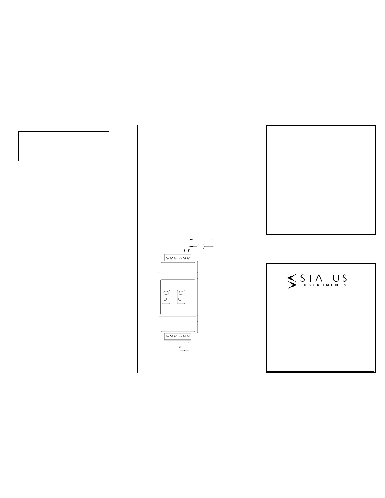
Care must be taken when designing the 4-20mA circuit to ensure that the
total burden of the loop, that is the total voltage requirements of all the
equipment in the loop added together, does not exceed the power supply
voltage. If a number of devices are connected in the loop, ensure that
only one instrument is tied to ground. Grounding the loop at two points
will result in shorting out part of the loop and therefore any transmitters in
that part of the loop will not operate.
Maximum load resistor, RL, is calculated as follows :
RL = (v-8)/20 x 1000
For 24V supply :
RL = (24-8)/20 x 1000 = 800R
3.3 EMC
This transmitter conforms with EC directives BS EN 50081-1 and
BS EN 50082-2 when correctly installed in a termination head providing
at least IP20 protection and fitted with a sensor with less than 3 metres
of cable.
4.0 RANGES
This transmitter is normally supplied ranged 0 to 100ºC, unless a special
range has been requested at the time of order. With the aid of suitable
equipment, this transmitter can programmed to a different range by
following the simple procedure listed below.
4.1 Equipment
The following apparatus will be required in order to re-range the
transmitter:-
• Power supply voltage between 10-30 V DC, 30 mA min current
• RTD Calibrator or Precision resistance box (0 - 390R)
• Connecting cables
• 3 mm Diameter screw driver or similar device.
• Current meter 0 - 20mA to monitor loop current.
4.2 Method (See Figure 4)
1. Connect circuit as shown in Figure 4 and set the RTD calibrator for
temperature required at 4mA.
2. Press and hold the programming switch by inserting a 3mm diameter
screw driver blade through the programming hole, located in the top
face of the transmitter housing. Hold the switch for approximately 5
seconds, until the RED programming led flashes. Release the switch.
3. Set the RTD calibrator for the required temperature at 20mA. Allow
10 seconds settling time, then press and release the programming
switch. The programming LED will flash quickly for a few moments,
then go out. The transmitter is now ranged.
4. Check the transmitter output range is correct by setting the RTD
calibrator to the 4mA and then 20mA settings, checking the output
current reading on the meter.
4.3 Calibration Circuit
SEM523P
DIN RAIL MOUNTED
DUAL CHANNEL
TEMPERATURE
TRANSMITTER
Designed, manufactured and supported by
Green Lane Business Park
Green Lane, Tewkesbury
Glos. GL20 8DE. UK
Sales: +44 (0) 1684 296 818
Support: +44 (0) 1684 296 818
Fax: +44 (0) 1684 293 746
Email: [email protected]
Every effort has been taken to ensure the accuracy of this
specification, however we do not accept responsibility for
damage, injury, loss or expense resulting from errors and
omissions, and we reserve the right of amendment without
notice.
Stock code: 52-214-2320-01 Issue: A
R
Box
10-30V DC
mA
0V
CH1 CH2
910111287
12 6345
SWITCH
LED
Figure 3
Burnout
Due to the sensing method, certain combinations
of open circuit sensor wires may result in the
output current dropping for approximately 500mS,
before rising to upscale output.
Page 2
1.0 DESCRIPTION
The transmitter is a dual channel DIN rail mounted 4-20mA transmitter
that connects to any standard Pt100 sensor and converts the sensor
temperature to a 4-20 mA signal.
An LED provides a visual indication of sensor fault and programming
mode. The transmitter is simply ranged and calibrated on the bench by
using a single on-board push button switch, without the need for soldering
links. Digital technology ensures accurate and drift free linearisation to all
common curves, providing a level of performance not possible with earlier
analogue types.
2.0 SPECIFICATION @ 20ºC
2.1 Input
Input Type 3 Wire Pt100
(Pt500 or Pt1000 to special order)
Linearisation BS EN 60751 (IEC751)
BS 1904 (DIN 43760)
JISC 1604
Excitation Current 1mA Maximum
Range -200 to 850ºC
Minimum Span 20ºC
Lead Resistance <10 R per leg (balanced)
Burnout Upscale 22mA
(Downscale preset current to order)
Red programming LED illuminates when
temperature is outside -200 to 850ºC range
Accuracy ±0.1ºC ± 0.1% of reading range -100 to 500
±0.2ºC ± 0.1% of reading range -200 to 850
Thermal Drift Zero ± 0.01C / ºC
Span 50 ppm
Connections Screw Terminals Two part
2.2 Output
Output 4 to 20 mA, 2 wire loop powered
Maximum Output Range 3.8 to 22 mA
Operating Voltage 8 to 30 V DC
Accuracy ± 5uA
Thermal Drift ± 1uA/°C
Response Time 500mS to reach 70% of final value
Loop Resistance 800R @ 24 V DC
Loop Sensitivity 0.4 µA / volt
Loop Noise ±0.001 µA
Protection Reverse Polarity Protected
Connections Screw Terminals
Input/Output Isolation Not isolated
Channel to
Warm-up Time 2 Minutes to full accuracy
EMC Emissions BS EN50081-1
Susceptibility BS EN50082-2
Ambient Temp. Range 0 to 70 ºC
Ambient Storage -40 to 70 ºC
Ambient Humidity 0 to 95 % (Non condensing)
Default Range 0-100ºC. Contact sales office for factory
configuration to any other range.
3.0 INSTALLATION
3.1 Mechanical
This transmitter has been specifically designed to be mounted on a
universal DIN rail inside an enclosure, which must provide adequate
protection from moisture, corrosive atmosphere etc. All cable entries
should be sealed using the correct size cable gland. Care must be taken
when locating the transmitter to ensure the ambient temperature will
remain inside the specified range of 0 to 70 ºC. The diagrams show the
mechanical layout and a typical application of the transmitter mounted on
a universal DIN rail, with sensor wires entering at the top and bottom of
the unit.
Side View Front View
Rail (DIN EN 50022-35)
3.2 Electrical
Connections to the transmitter are made by screw terminals. To maintain
CE compliance, input and output wiring must be screened cable with the
screen earthed at one end only. All three input wires must have the same
core diameter to maintain equal lead resistance in each wire.
The transmitter is protected against reverse connection, therefore
incorrect connection of the output wires will result in near zero current
flowin the loop. Incorrect connection of the sensor wires will result in the
transmitter output going to burnout condition.
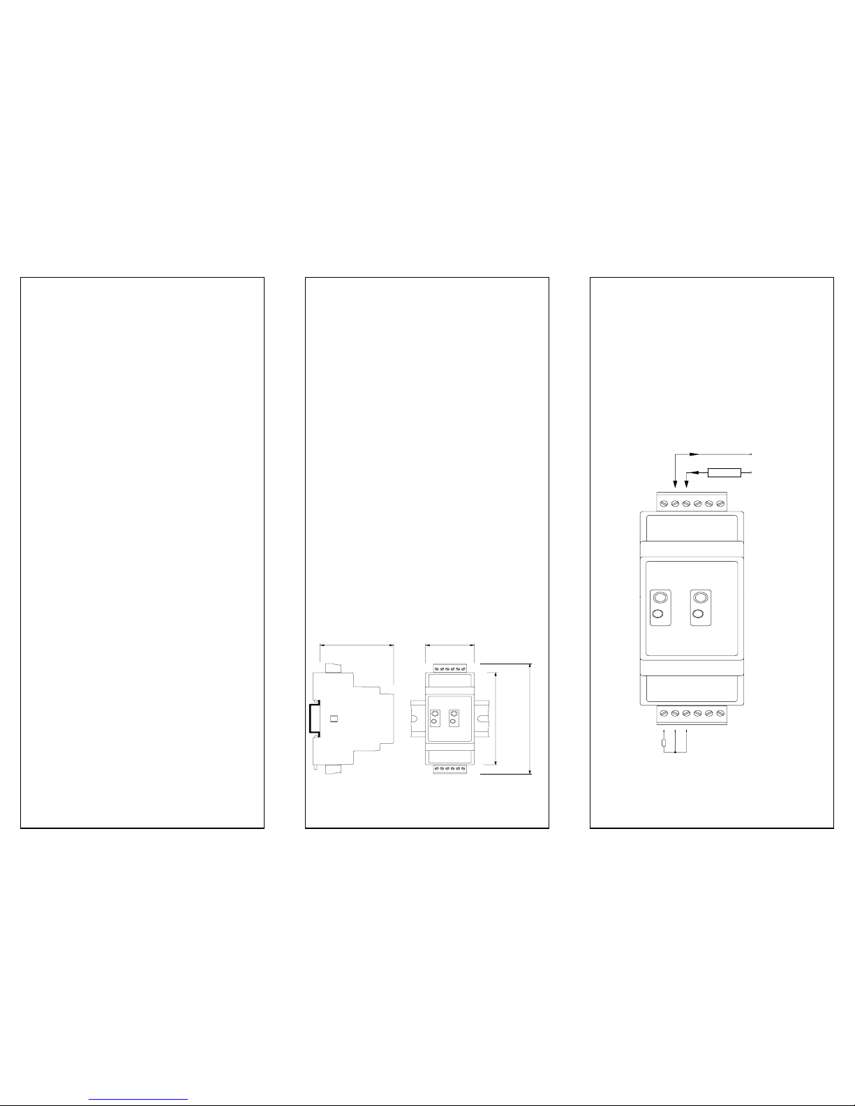
Figure 2 shows the method of connection to provide a 4-20 mA current
loop output. The Pt100 sensor shown would normally take the form of a
probe assembly with a three wire output. The output loop shows a 24
VDC power supply, used to provide loop excitation, the transmitter, and a
load, all connected in series. The load symbol represents other equipment
in the loop e.g. indicators, controllers, loggers etc.
52.9 35.0
CH1 CH2
910111287
12 6345
86.0 103.0
SWITCH
LED
Figure 1
+24V
0V
CH1 CH2
910111287
12 6345
SWITCH
LED
LO AD
PT SENSOR
Figure 2
52-214-2320-01
 Loading...