

Page 1
Every effort has been taken to ensure the accuracy of this document, however we do not accept responsibility for damage, injury, loss or expense resulting from
errors and omissions, and we reserve the right of amendment without notice.
Status Instruments Ltd, Status Business Park, Gannaway Lane, Tewkesbury, Gloucestershire, UK, GL20 8FD
Web Page: www.status.co.uk Tel : +44 (0) 1684 296818 Fax: +44 (0) 1684 293746
User instruction for SEM210X electrical apparatus for use in a hazardous area.
Important: Read and understand this document before any installation.
ATEX & IECEx Instructions
For safe installation of the SEM210X in hazardous areas the following instructions must be observed. The transmitter must be installed by
competent personnel, who are familiar with national and international laws, directives and standards that apply to their region. For
installation in European Economic Area (EEA) member countries users must follow requirements for electrical equipment for use in
potentially explosive atmospheres, e.g. EN60079-14 & EN60079-17. This instruction sheet describes installation, which conforms with BS
EN60079-14 & BS EN60079-17. Important - Particular attention must be paid to the section titled "Special conditions for safe use", failure
to comply to this requirement will result in an unsafe system.
The SEM210X has been issued with a EU-type examination certificate, confirming compliance with European ATEX directive 2014/34/EU
for the following specification :-
Manufacturer Status Instruments Ltd
Type Number SEM210X
Zones
Product Information
Certificate Ref EMT16ATEX0005X
Classification
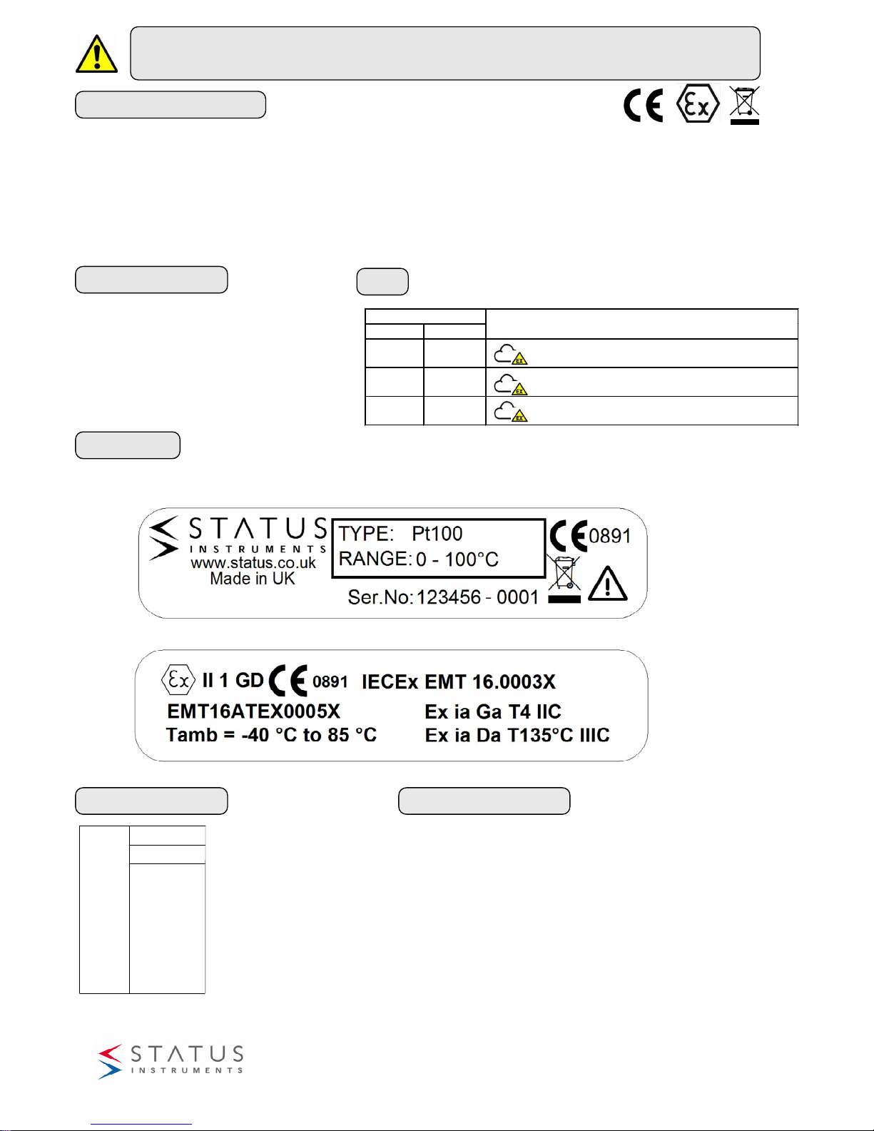
The following Information is printed on the
product label
Working Parameters Additional Information
EMC BS EN 61326-1
(Sensor wires maximum length 3 metres to comply.)
Enclosure Colour Blue
SER No. 000000 - 0001
www.status.co.uk
Made in UK
0891
II 1 GD
IECEx TRC 10.0008X
Ex ia IIC T4 Ga
Ex iaD 20 T135 °C Da
Tamb = -40 °C to 85 °C
Terminals
+ / Ui = 30 V
Ii = 100 mA
Pi = 750 mW
Ci = 0
Li = 0
Uo = Io = Po = -
D2578-01-02 SEM210X User Guide Page 1 of 4
Area Classification
Gases Dusts
Zone Criteria for Application Atmosphere
Zone 0
Zone 20
Present continuously or for long periods
(> 1000 hours per annum)
Zone 1
Zone 21
Likely to occur in normal operation occasionally
(> 10 to < 1000 hours per annum)
Zone 2
Zone 22
Unlikely to occur in normal operation
(< 10 hours per annum)
“Model”
TRAC ????
SEM210X
2016-11
Example of Type and Range shown below
Page 2
D2578-01-02 SEM210X User Guide Page 2 of 4
Mechanical Detail
Maintenance
The appropriate regulations concerning maintenance, repair and testing must be observed. In particular, all parts on which explosion
protection depends must be checked during maintenance. The transmitter must never be configured in the hazardous area, the device must
be removed and taken to a non hazardous area for configuration.
The enclosure used to house the SEM210X must be cleaned regularly to prevent build up of excessive dust layers.
The SEM210X apparatus contains no user serviceable adjustable, replaceable parts. No attempt should be made to repair a SEM210X
device, all units must be returned to the manufacturer for repair or replacement. Attempted service or replacement of parts may invalidate
the explosive protection features of the SEM210X.
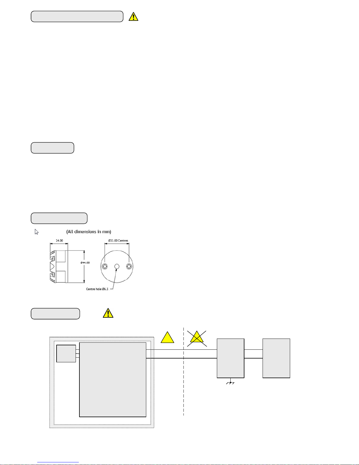
The SEM210X is mounted using two holes, on standard 33 mm fixing centres and
will fit a DIN standard termination head. The SEM210X must be installed with
adequate protection from moisture and corrosive atmospheres. Refer to "special
conditions for safe use" section of this user guide for information on enclosure IP
rating.
Care must be taken to ensure the SEM210X is located to ensure the ambient
temperature does not exceed the specified operating temperature as specified in the
"TEMPERATURE CLASS" table.
A 6.3 mm hole is provided in the centre of the transmitter for sensor wires.
The sensor wires may also be fed on the outside of the transmitter.
Electrical Detail
REFER TO CONDITIONS FOR SAFE USE
Special conditions for safe use
1. a) For gas applications, the SEM210X temperature transmitters must be mounted in an ATEX/IECEx approved enclosure rated for IP54
and located in an area where the enclosure will not be subject to impact or friction
b) For dust applications, the SEM210X temperature transmitters must be mounted in a suitably ATEX or IECEx certified enclosure
appropriate for the zone of end use.
2. The equipment shall only be configured by means of the USB connection outside the hazardous area.
3. If the equipment is mounted in an enclosure with separate IS circuits, appropriate segregation shall be provided in accordance with
IEC 60079-11 Clause 6.2.1.
4. Only suitable for connection to Thermocouple(s), RTD temperature sensor(s) or slide wire resistance devices or a simple
apparatus. They shall conform to the requirements for simple apparatus as defined in IEC 60079-11 clause 5.7 and shall meet the
dielectric withstanding requirements of IEC 60079-11 clause 6.3.13. The insulation must be capable of withstanding an r.m.s a.c. test
voltage of 2U + 1000V, with a minimum of 1500V r.m.s., where U is the sum of the voltages of the intrinsically safe and the nonintrinsically safe circuit.
5. The ambient temperature range of the enclosure will limit the permitted ambient range of the overall equipment. Refer to
enclosure certification.
Sensor wires must be isolated from earth breakdown voltage 500 V dc
Sensor
Hazardous Area
Non Hazardous Area
EX
EX
Barrier
SEM210X
CE II 1 GD
Ex ia IIC T4 Ga
Ex ia 20 T135 °C Da
Tamb = -40 °C to 85 °C
DC Supply
Earth
Ui = 30V
Ii = 100mA
Pi = 750mW
Li = 0
Ci = 0
2016-11
Page 3
Installation
For SEM210X specification please refer to product data sheet. Installation is normally performed in the following order. If the SEM210X has
been purchased as part of a probe assembly ,steps (1 to 3 ) will have been completed. The user may wish to reconfigure the transmitter
range, in this instance the SEM210X range can be changed on a completed probe assembly by following step 1.
1. Configuration
2. Mount Transmitter into head
3. Wire Sensor
4. Install Assembly
5. Wire (4 to 20) mA Loop
REFER TO CONDITIONS FOR SAFE USE
Factory default setting Sensor PT100 range (0 to 100) °C,
Visit
www.status.co.uk
download latest
version of
USBSpeedLink
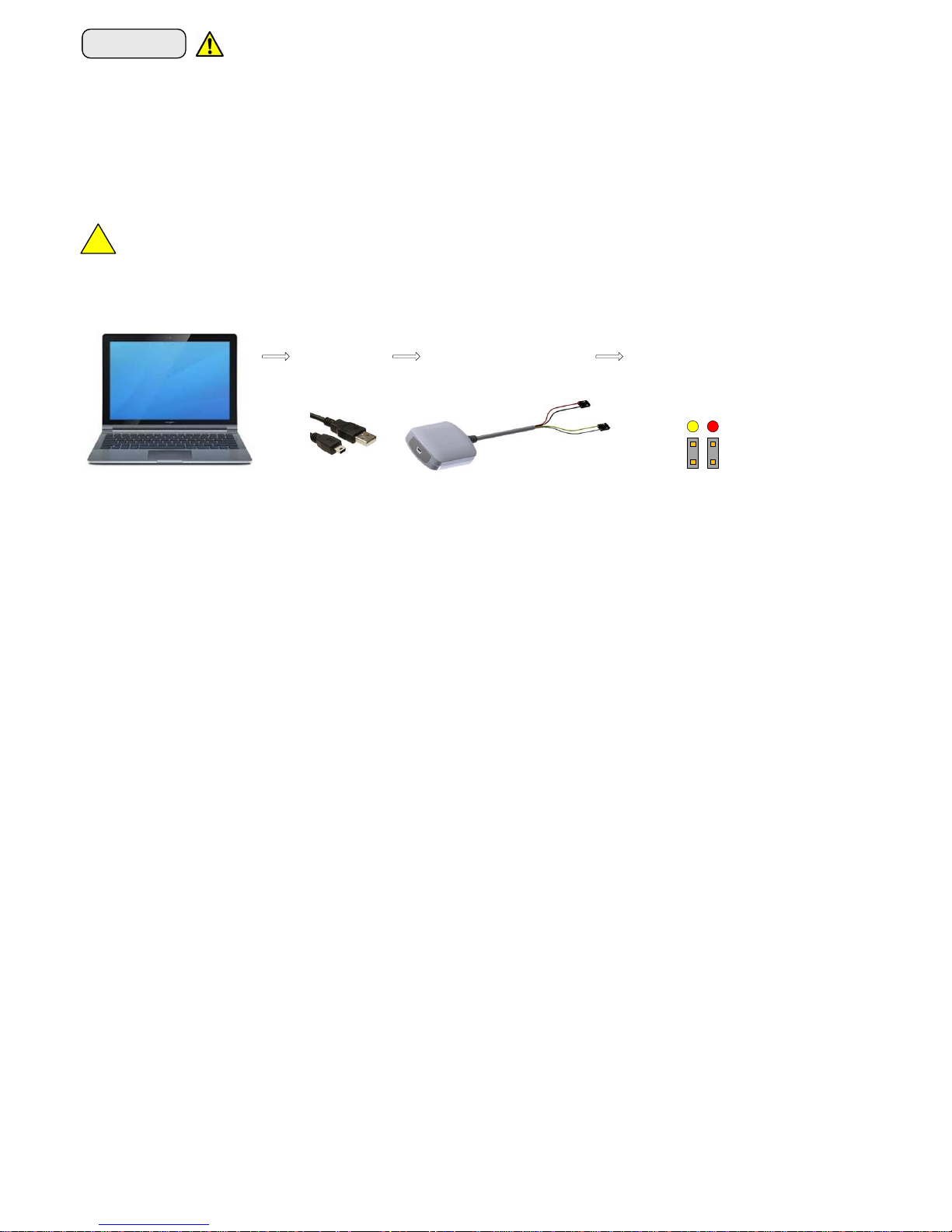
1. Configuration – Only to be performed in the safe area
Once software is i nstalled
remove protection cover from
device port , plug in configurator
plugs in to device ports and
connect PC to configurator using
USB cable.
In USBSpeedLink software, select Model type from
“Field Product – In Head TX” menu.
For further information on configuration please open
the help menu on the product configuration screen.
On completion of configuration remove USB cable
and replace protective cover over socket.
EX
The main configuration is performed using the USB interface. The following parameters may be configured using the powerful USBSpeed link software tool,
which also provide operator diagnostics.
The following functions apply :-
SENSOR
Sensor type mV, Dual mV, ohms, slide wire, thermocouple, dual thermocouple, RTD, dual RTD (2 wire).
Sensor wire (ohms and rtd ranges only) 2, 3, or 4 wire.
Thermocouple type Download from USBspeedlink expanding library, common type K,J,T,E,R,S,N,B,U,G,C,D.
Thermocouple CJ Fixed or Auto.
RTD type Download from USBspeedlink expanding library, common type PT100, PT1000, PT500, Ni, CU, KTY series.
Sensor(s) Fail Value on sensor A, (sensor B) fail.
Sensor Pre-set Override sensor signal with pre-set value, primary function diagnostics.
PROCESS
Scaling Scale sensor signal to PV, options - Off, Two point scaling or (4 to 22) step profile.
Units Set PV units
mA Output
Damping Profile out damping (0 to 32) seconds.
Range Range (PV units) For (4 to 20) mA output.
Fix Loop Current Fix loop current to pre-set value (Note resets on power up) . Primary use Diagnostics.
Set Max mA Set the maximum output current (20 to 23)mA.
Set min mA Set minimum output current (3.5 to 4.0) mA.
Trim Read set and reset (4 and 20) mA Trim values.
DIAGNOSTICS
Power ups Number of power ups from manufacture.
Min Max PV Minimum and maximum process variable value during operation with reset.
Operating times From manufacture and calibration. Calibration time is resettable.
Calibration Store Date, operator and certificate number.
Save Data Save transducer data to text file.
DIAGNOSTCS LOG
Type 150 point non volatile Process Variable log, with power off indication and sensor fail (not time stamped).
Rates User set log periods seconds 5, 15, 30 minutes 1, 2, 5, 10, 20, 30, or 60.
Backup Save log to PC in CSV style format (using semi colon delimiter) for easy export to text editor or spreadsheet.
PROCESS DATA
Data Live data for sensor (TV) ,pre-scaling, post scaling (PV), Untrimmed mA output, Actual mA output, % output signal
and device ambient temperature (SV) (cold junction).
Diagnostics Sensor wire error detect (not supported in mV mode), Loop power detect.
D2578-01-02 SEM210X User Guide Page 3 of 4
Red
Yellow
2016-11
Note: - The SEM210X can be configured whilst connected and powered, but a portable battery powered computer
must be used to avoid the effects of ground loops if the (4 to 20) mA loop is grounded. This may damage the
SEM210X. Only to be performed in the safe area.
Page 4
D2578-01-02 SEM210X User Guide Page 4 of 4
2. Mount Transmitter into Head
The SEM210X is mounted using two holes, on standard 33 mm fixing centres and will fit a DIN standard termination head. The SEM210X
must be installed with adequate protection from moisture and corrosive atmospheres. Refer to "special conditions for safe use" section of
this user guide for information on enclosure IP rating. A centre hole is provided in the SEM210X case, this allows for sensor wire to enter
wiring section through the SEM210X body. Observe the "special conditions for safe use " instruction.
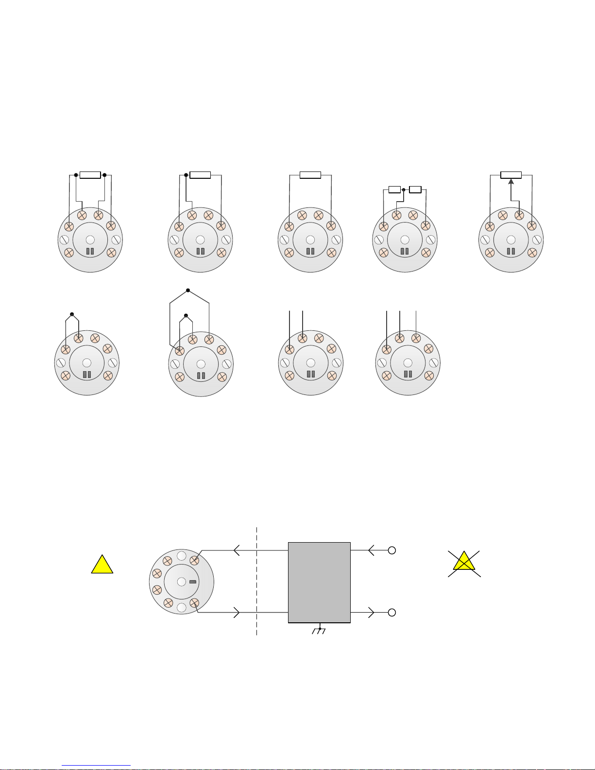
3. Sensor Connection
4. Install assembly
Care must be taken to ensure the SEM210X is located to ensure the ambient temperature does not exceed the specified operating
temperature (-40 to 85) °C
5. Wire (4 to 20) mA Loop
Ensure all other aspects of the installation comply with the requirements of this document, paying particular attention to the loop
barrier. The (4 to 20) mA loop is connected as follows:-
Barrier
+
-
dc Supply
Earth
Hazardous Area
Non Hazardous Area
EX
EX
4 Wire Resistance (RTD)
USB
2 1
3
4 5
6
3 Wire Resistance (RTD)
USB
2 1
3
4 5
6
2 Wire Resistance (RTD)
USB
2 1
3
4 5
6
mV
USB
2 1
3
4 5
6
+-
Dual mV
USB
2 1
3
4 5
6
+-
+
BA
Dual RTD (2 wire)
No Redundancy
USB
2 1
3
4 5
6
A B
Slide Wire
USB
2 1
3
4 5
6
Thermocouple
USB
2 1
3
4 5
6
-
+
Dual Thermocouple
USB
2 1
3
4 5
6
+
-
+
A
B
USB
2 1
3
4 5
6
2016-11
 Loading...