

Page 1
D2186-02-08 CN5232 SEM210 User Guide Page 1 of 2
1
.0 GENERAL
The transmitter is a second generation 'Smart' in head temperature transmitter that
accepts any commonly used temperature sensor, slidewire transducer or millivolt
signal and converts the output to the industry standard (4 to 20) mA transmission signal.
The software package M-Config with the USB Configuration module can be used to
program the unit.
2.0 SPECIFICATION@ 20 °C
2.11 RTD Input (Pt100)
Sensor Range (-200 to +850) °C (18 to 390) Ω
M
inimum Span¹ 25 °C
Linearisation BS EN 60751 (IEC 751)
BS 1904 (DIN 43760)
JISC 1604
Basic Measurement Accuracy ² ± 0.01 % FRI ± 0.05 % Rdg
(FRI = Full Range Input), (Rdg = Reading)
Thermal Drift Zero (0.008 °C / °C) Span (0.01% / °C)
Excitation Current 300 µA to 550 µA
Maximum Lead Resistance 50 Ω / leg
Lead Resistance Effect 0.002 °C / Ω
2
.12 Thermocouple Input
Sensor Ranges Thermocouple
Type
Measuring
Range 3 °C
Minimum
Span 1 °C
TC Type K -200 to 1370 50
TC Type J -200 to 1200 50
TC Type T -210 to 400 25
TC Type R -10 to 1760 100
TC Type S -10 to 1760 100
TC Type E -200 to 1000 50
TC Type L -100 to 600 25
TC Type N -180 to 1300 50
Linearisation BS 4937 / IEC 584, EN60584
Basic Measurement Accuracy ² ± 0.04 % FRI ± 0.04 % Rdg or 0.5 °C
(Which ever is greater)
(FRI = Full Range Input), (Rdg = Reading)
Thermal Drift Zero 0.1 µV / °C Span 0.01% / °C
Cold Junction Error ± 0.5 °C
Cold Junction Tracking 0.05 °C / °C
Cold Junction Range (-40 to +85) °C
2.13 Millivolt Input
Input Voltage Source
Range (-10 to +75) mV
Characterisation Linear
Minimum Span¹ 5 mV
Basic Measurement Accuracy ² ± 10 µV ± 0.07 % Rdg
Input Impedance 10 MΩ
Thermal Drift Zero (0.1 µV / °C) Span (0.01% / °C)
2.14 Slidewire Input
Input 3 Wire potentiometer
Resistance Range (10 Ω to 390 Ω) (End to End)
Larger values can be accommodated by
external resistor
Characterisation Linear
Minimum Span ¹ 5 % of FRI
Basic Measurement Accuracy ² 0.1 % of FRI
Thermal Drift 0.01 % / °C
Notes.
1. Any span may be selected, full accuracy is only guaranteed for spans
greater than the minimum recommended.
2. Basic Measurement Accuracy includes the effects of calibration,
linearisation and repeatability.
3. Consult thermocouple reference standards for thermocouple material
limitation.
2.2 Output
Output Range (4 to 20) mA (>3.8 to <20.2) mA
Maximum Output 23 mA
Accuracy ± 5 µA
Voltage Effect 0.2 µA / V
Thermal Drift 1 µA / °C
Supply Voltage (10 to 35) VDC
Maximum Output Load [(Vsupply -10)/20] KΩ (eg 700 Ω @ 24V)
2
.3 General
Input/Output Isolation 500 VAC rms (galvanically isolated)
Update Time 250 ms Maximum
Time Constant (Filter Off) < 1 s (Time to reach 63% final value)
Filter Factor Programmable Off, 2 s, 10 s or adaptive
Warm-up Time 120 s to full accuracy
Environmental
Ambient Operating Range (-40 to 85) °C
Ambient Storage Temperature (-50 to 100) °C
Ambient Humidity Range (10 to 90) % RH non condensing
Approvals
Emc BS EN 61326
Mechanical
Enclosure DIN standard terminal block size
Material ABS
Weight 35 g
Dimensions 43 mm diameter x 21 mm
Communications
PC Interface USB via configurator
Maximum Cable Length 1000 m
Configurable Parameters Sensor type: Burnout: °C / °F: Output:
Hi / Lo: Filter: Tag: User Offset
2.4 SEM210X VERSION - FOR USE IN POTENTIALLY EXPLOSIVE ATMOSPHERES
2.4.1 ATEX Certificate
The SEM210X, has been issued with a EC-type examination certificate, confirming
compliance with the European ATEX directive 94/9/EC for :-
Intrinsic safety II 1 G EEx ia IIC T4…T6.
The equipment bears the Community Mark and subject to local codes of practice, may be
installed in any of the European Economic Area (EEA) member countries. The SEM210X
housing is coloured light blue to identify the equipment as suitable for Hazardous area
use. The equipment must be installed and maintained in
accordance with local requirements for electrical equipment for use in potentially
explosive atmospheres, eg EN60079-14 & EN60079-17. This instruction sheet describes
installation which conforms with BS EN60079-14 & BS EN60079-17 Electrical Installation
in Hazardous Areas. When designing systems outside the UK, the local Code of Practice
should be consulted.
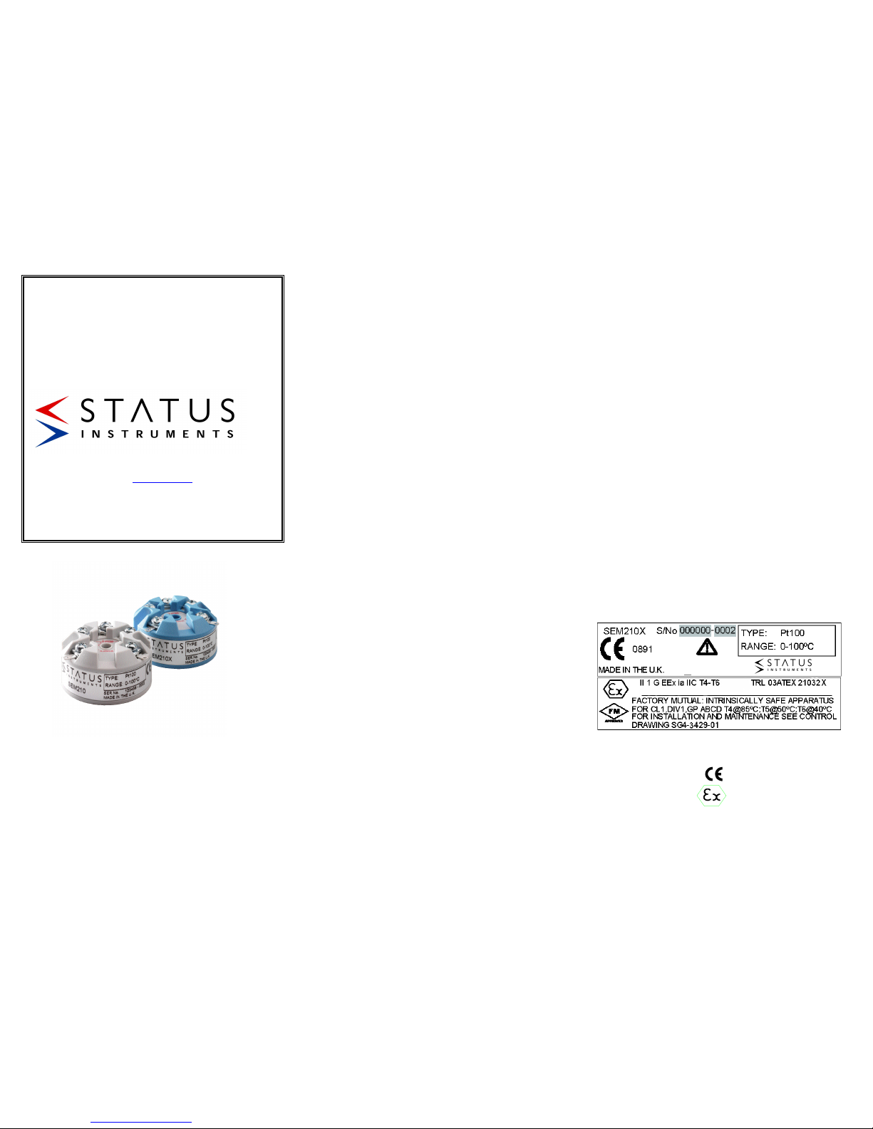
2.4.2 ATEX Marking
Common Information
Manufacturer Status Instruments Ltd
Type Number SEM210X
CE marking 0891
Explosive Protection Marking
SEM210
PROGRAMMABLE IN HEAD
TEMPERATURE
TRANSMITTER
Designed, manufactured and supported by:
Status Business Park, Gannaway Lane
Tewkesbury Glos. GL20 8FD. UK
Tel: +44 (0)1684 296818 Fax: +44 (0)1684 293746
Email: [email protected]
Every effort has been taken to ensure the accuracy of this specification, however we do
not accept responsibility for damage, injury, loss or expense resulting from errors and
omissions, and we reserve the right of amendment without notice
Stock code 51-214-2186-02 Issue 8
Page 2
D2186-02-08 CN5232 SEM210 User Guide Page 2 of 2
(Type ia) Intrinsic Safety
II 1 Equipment Group and category
G Type of explosive atmosphere (Gas)
EEx ia IIC T4..T6 Intrinsic safety information
TRL03ATEX21032 X Certificate reference
2.4.3 Special Conditions for Safe Use
As indicated by the Certificate Reference "X" suffix, special conditions apply for safe use
for both intrinsic safety and energy limitation applications. They are as follows:-
2.4.3.1 Zones, Gas Groups, and T rating.
When connected to a approved system the SEM210X may be installed in:Zone 0 explosive gas air mixture continuously present
Zone 1 explosive gas air mixture likely to occur in normal use
Zone 2 explosive gas air mixture not likely to occur and if it does,
it will only occur for a short time.
Be used in gas groups;Group A propane
Group B ethylene
Group C hydrogen
Allowable Temperature classification / ambient temperature:-
Intrinsic safety (Type ia)
Class Ambient Temperature
Range
T1 450°C -25 to 85 °C
T2 300°C -25 to 85 °C
T3 200°C -25 to 85 °C
T4 135°C -25 to 85 °C
T5 100°C -25 to 50 °C
T6 85°C -25 to 40 °C
2.4.3.2 Environmental protection
This equipment must be housed in an enclosure which provides a degree of
protection of at least IP54. The enclosure must be suitable for the atmosphere and
environment in which it is installed. (eg If of a plastic material, must be resistant to
chemical corrosion, UV light, temperature, humidity, etc).
2.4.3.3 Maintenance
This intrinsically safe equipment contains no user serviceable, adjustable or
replaceable parts. No attempt should be made to repair a faulty SEM210X transmitter, all
units must be returned to the manufacture for repair or replacement. Attempt
service or replacement of parts may invalidate the explosive protection features of the
equipment.
2.4.3.4 Connection Diagram
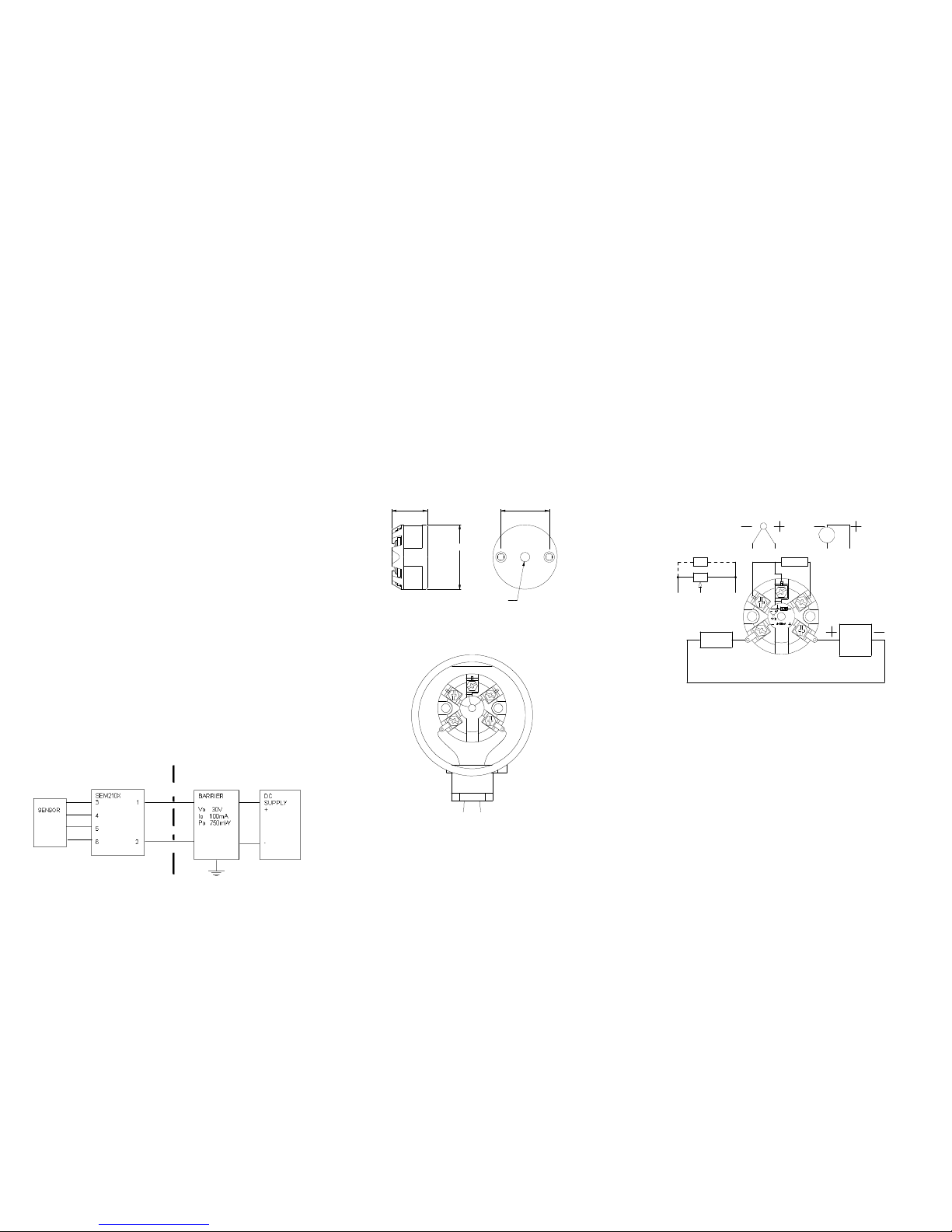
They equipment must be electrically connected as shown below:-
SEM210X Working Parameters
Ui 30 V
I i 100 mA
Pi 750 mW
Ci 10 nF
Li 0
3.0 INSTALLATION
3.1 Mechanical
The transmitter is mounted using two 5.5mm diameter holes, on standard 33 mm
fixing centres and will fit a DIN standard termination head. The transmitter should be
installed with adequate protection from moisture and corrosive atmospheres.
Care must be taken when locating the transmitter to ensure the ambient temperature
remains within the specified operating range. Figure 1 shows the mechanical layout and
a typical application of the transmitter mounted inside a termination head
enclosure, with sensor wires entering through the centre of the transmitter body.
Figure 1
3.2 Electrical
Connections to the transmitter are made to the screw terminals provided on the top face.
No special wires are required for the output connections, but screened twisted pair cable
are the most suitable for long runs. It is recommended that screened cable is used for the
three input signal wires for cable runs greater than one metre. All three input wires must
have the same core diameter to maintain equal lead resistance in each wire. A Ø4.5 mm
hole is provided through the centre of the transmitter to allow sensor wires to be threaded
through the transmitter body direct to the input screw
terminals. The screw terminals have been designed to allow all connection wires to enter
from an inner or an outer direction.
Figure 2 shows the method of connection to provide a (4-20) mA current loop output. The
Pt100 sensor shown would normally take the form of a probe assembly with a three wire
connection. The output loop has a voltage power supply used to provide loop excitation.
The load symbol represents other equipment in the loop, normally indicators, controllers
or loggers. Care must be taken when designing the (4-20) mA circuit to ensure that the
total voltage requirements of all the equipment in the loop added together, does not
exceed the power supply voltage. If a number of instruments are connected in the loop,
ensure that only one instrument is tied to ground. Grounding the loop at two points will
cause a short circuit of part of the loop leading to measurement errors.
To guarantee CE compliance, sensor leads must be less than 3 metres long and the
transmitter housing should prevent access to the transmitter during normal operation.
Figure 2
* Fit Rx for all potentiometers with end to end resistance >390 ohms. Such that total end
to end resistance is >200 ohms <390 ohms.
24.00
Ø44.0 0
Ø33.0 0 Cen tres
Centre h o le Ø6.3
Cable
Entry
4-20mA
Loop
Enclosure
Millivolt
Power
Supply
Load
PT100
TC
mV
10 to 35 VDC
3 4
3 4 5
3 4
2 1
3 4 5
Slidewire
Rx
 Loading...