

Statpower PROwatt 1500/12 volt, PROwatt 1500/24 volt, PROwatt 1500 Owner's Manual

TM
PROwatt 1500/12 volt
TM
PROwatt 1500/24 volt
POWER INVERTER
Owner’s
Manual
Statpower Technologies Corporation
7725 Lougheed Highway
Burnaby, BC V5A 4V8
Canada
PROwatt is a trademark of Statpower Technologies Corporation.
Copyright © 1996, 1997 Statpower Technologies Corporation. All rights reserved.
Internet address: http://www.statpower.com
Tel: (604) 420-1585
Fax: (604) 420-1591

Table of Contents
1 Introduction...........................................................................................................................................................
2 How Your PROwatt 1500 Works.........................................................................................................................
2.1 Principle of Operation .............................................................................................................................
2.2 PROwatt 1500 Output Waveform...........................................................................................................
3 Quick Checkout....................................................................................................................................................
3.1 Power Source...........................................................................................................................................
3.2 Cables......................................................................................................................................................
3.3 Test Loads ...............................................................................................................................................
3.4 Connections.............................................................................................................................................
4 Installation ............................................................................................................................................................
4.1 Where to Install.......................................................................................................................................6
4.2 Battery.....................................................................................................................................................
Battery Type
Battery Sizing
Using Multiple Batteries
Battery Tips
Alternators and Charging Systems
4.3 Cables....................................................................................................................................................
4.4 Connections...........................................................................................................................................
AC Wiring
Ground Wiring
DC Wiring
4.5 Remote Panel.........................................................................................................................................
Installation Instructions
Operating Instructions
.....................................................................................................................................7
...................................................................................................................................8
..................................................................................................................9
....................................................................................................................................10
.................................................................................................11
......................................................................................................................................12
..............................................................................................................................15
......................................................................................................................................16
..................................................................................................................17
....................................................................................................................17
1
1
1
3
4
4
4
5
5
6
6
12
12
17
5 Operation ............................................................................................................................................................
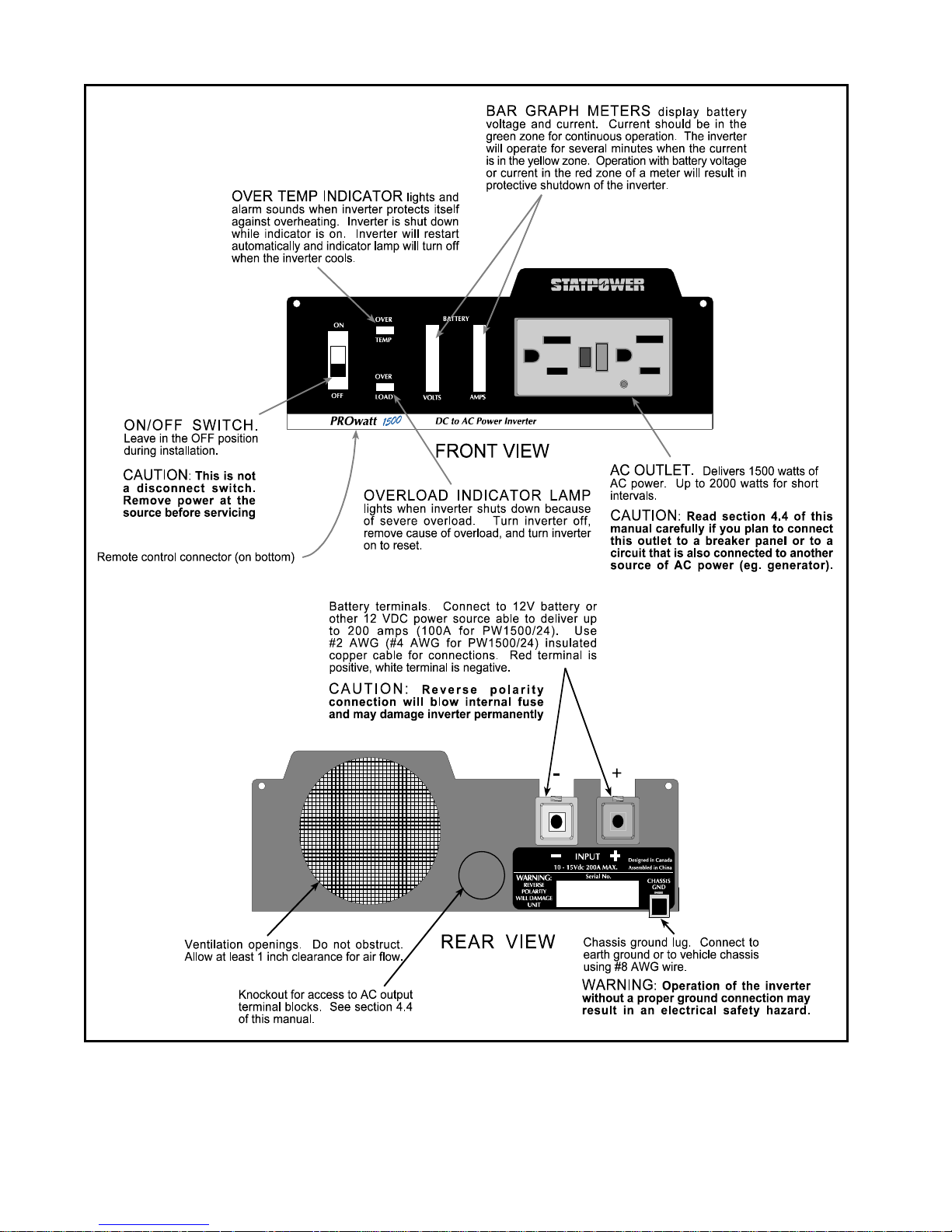
5.1 Outlets, Controls and Indicators............................................................................................................
5.2 Operating Limits...................................................................................................................................
6 Troubleshooting..................................................................................................................................................
6.1 Common Problems................................................................................................................................
6.2 Troubleshooting Guide..........................................................................................................................
7 Maintenance........................................................................................................................................................
8 Warranty.............................................................................................................................................................
8.1 Warranty Terms.....................................................................................................................................22
8.2 To Obtain Warranty Service.................................................................................................................
9 Specifications ......................................................................................................................................................24
9.1 Electrical Perform
9.2 Dimensions............................................................................................................................................
ance ..........................................................................................................................24
18
18
19
20
20
21
22
22
22
24
PROwatt is a trademark of Statpower Technologies Corporation.
Copyright © 1996, 1997 Statpower Technologies Corporation. All rights reserved.

1 Introduction
Your new PROwatt 1500 inverter is a member of the most advanced line of dc to ac inverters available today. It
will give you years of dependable service in your boat, RV, service vehicle or remote home.
To get the most out of your PROwatt 1500, it must be installed and used properly. Please read the installation and
operating instructions in this manual carefully before installing and using your PROwatt 1500. Pay special attention to the CAUTION and WARNING statements in this manual and on the PROwatt 1500. CAUTION statements identify conditions or practices which could result in damage to your PROwatt 1500 or to other equipment.
WARNING statements identify conditions or practices that could result in personal injury or loss of life.
2 How Your PROwatt 1500 Works
An inverter is an electronic device that converts low voltage DC (direct current) electricity from a battery or other
power source to standard 115 volt AC (alternating current) household power. In designing the PROwatt 1500,
Statpower has used power conversion technology previously employed in computer power supplies to give you
an inverter that is smaller, lighter, and easier to use than inverters based on older technology.
2.1 Principle of Operation
The PROwatt 1500 converts power in two stages. The first stage is a DC-to-DC converter which raises the low
voltage DC at the inverter input to 145 volts DC. The second stage is the actual inverter stage. It converts the
high voltage DC into 115 volts, 60 Hz AC.
The DC-to-DC converter stage uses modern high frequency power conversion techniques that eliminate the bulky
transformers found in inverters based on older technology. The inverter stage uses advanced power MOSFET
transistors in a full bridge configuration. This gives you excellent overload capability and the ability to operate
tough reactive loads like lamp ballasts and induction motors.
Figure 1. PROwatt 1500 - Principle of Operation
1
2
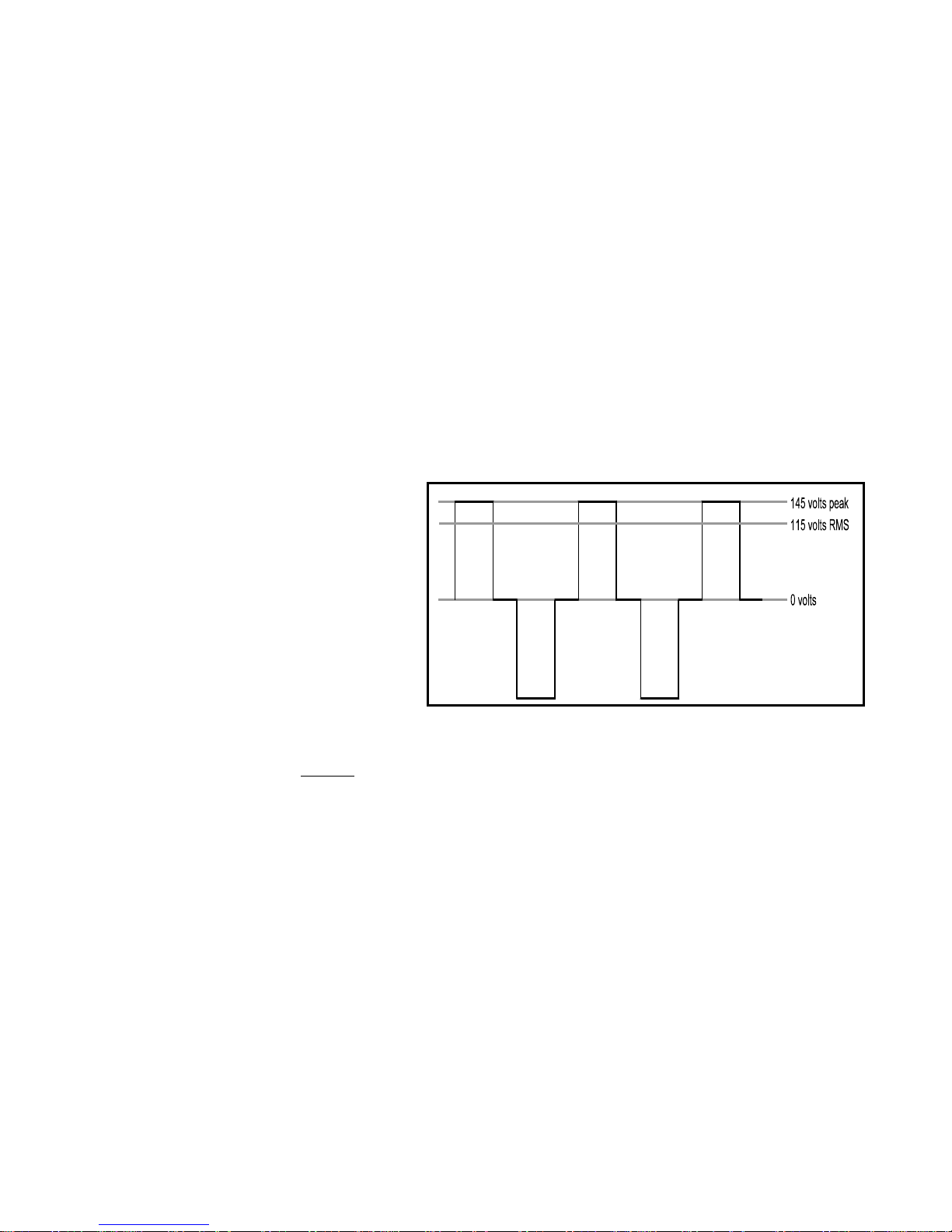
2.2 PROwatt 1500 Output Waveform
The AC output waveform of the PROwatt 1500 is called a "quasi-sine wave" or a "modified sine wave". It is a
stepped waveform that is designed to have characteristics similar to the sine wave shape of utility power. A
waveform of this type is suitable for most AC loads, including linear and switching power supplies used in electronic equipment, transformers, and motors. This waveform is much superior to the square wave produced by
many other dc to ac inverters.
CAUTION! RECHARGEABLE APPLIANCES
Certain rechargers for small nickel cadmium batteries can be damaged if connected to the PROwatt. Two
particular types of equipment are prone to this problem:
1) small battery operated appliances such as flashlights, razors, and night lights that can be plugged directly into an ac receptacle to recharge.
2) certain battery chargers for battery packs used in hand power tools. These chargers have a
WARNING label stating that dangerous voltages are present at the battery terminals.
Do NOT use the PROwatt with the above equipment.
This problem does not occur with the vast majority of battery operated equipment. Most of
this equipment uses a separate charger or transformer that is plugged into the ac receptacle
and produces a low voltage output. If the label
on the ac adapter or charger states that the
adapter or charger produces a low voltage ac or
dc output (less than 30 volts), the PROwatt will
have no trouble powering this charger or
adapter safely.
The modified sine wave produced by the
PROwatt 1500 is designed to have an RMS
Figure 2. Modified Sine Wave
(root mean square) voltage of 115 volts, the same as standard household power. Most AC voltmeters (both digital
and analog) are sensitive to the average
value of the waveform rather than the RMS value. They are calibrated for
RMS voltage under the assumption that the waveform measured will be a pure sine wave. These meters will not
read the RMS voltage of a modified sine wave correctly. They will read about 2 to 20 volts low when measuring
the output of the PROwatt 1500. For accurate measurement of the output voltage of the PROwatt 1500, a true
RMS reading voltmeter, such as a Fluke 87, Fluke 8060A, Beckman 4410, or Triplett 4200, must be used.
3

3 Quick Checkout
This section will give you the information you need to quickly hook-up your PROwatt 1500 and check its performance before going ahead with permanent installation. You will need the following:
a) a 12 volt DC power source (24 volt for PW1500/24)
b) two cables to connect the power source to the PROwatt 1500
c) a test load that can be plugged into the AC receptacle on the PROwatt 1500.
3.1 Power Source
The power source must provide between 11 and 15 volts (22 and 30 volts for PW1500/24) DC and must be able
to supply sufficient current to operate the test load. As a rough guideline, divide the wattage of the test load by 10
(by 20 for PW1500/24) to obtain the current (in amperes) the power source must deliver.
Example: Test load is rated at 250 watts. Power source must be able
to deliver 250 ÷ 10 = 25 amperes (or 12.5Amps for 24 volt model).
Battery
Use a fully-charged 12 volt (nominal) battery that can deliver the required current while maintaining its voltage
above 11 volts (22 volts for 24 volt battery system). A fully-charged (12 volt) automobile battery is capable of
delivering up to 50 amperes without an excessive voltage drop.
DC Power Supply
Use a well regulated
PW1500/24) and can deliver the required current. If the supply is adjustable, make sure that the output voltage is
adjusted to be between 11 volts and 15 volts (22-30 volts for PW1500/24) the inverter may shut down if the voltage is outside these limits and may be damaged if the voltage is above 16 volts (32 volts for PW1500/24). Also
ensure that any current limit control is set so that the power supply can deliver the required current.
3.2 Cables
Your cables must be as short as possible and large enough to handle the required current. This is to minimize the
voltage drop between the power source and the inverter when the inverter is drawing current from the power
source. If the cables introduce an excessive voltage drop, the inverter may shut down when drawing higher currents because the voltage at the inverter drops below 10 volts (20 volts on PW1500/24).
We recommend #2 AWG (#4 AWG on PW1500/24) stranded copper cable that is no longer than 4 ft (1.2 metres)
if you want to test the PROwatt 1500 to its maximum ratings. For short term testing at reduced power levels, the
guidelines below should be followed:
Test Load Power Minimum Cable Size Minimum Cable Size
Consumption For PW1500/12 volt PW1500/24 volt
Short Term Test
100 watts #16 AWG copper #18 AWG copper
250 watts #12 AWG copper #16 AWG copper
500 watts #8 AWG copper #12 AWG copper
Ideally, the cable should be no more than 4 ft (1.2 meters) long.
The end of the cable to be connected to the inverter must have its insulation stripped for about 1/2 inch (1.25 cm)
back from the end, exposing the bare copper conductor. The other end of the cable, which is connected to the
DC power supply that has an output voltage between 11 volts and 15 volts (22-30 volts for
4
power source, must be terminated with a lug or other connector that allows a secure, low resistance connection to
be made to the power source. For instance, if the power source is a battery, the cable must be terminated with a
battery terminal that clamps to the post on the battery.
A solid, low resistance connection to the power source is essential for proper operation of the PROwatt
1500.
3.3 Test Loads
Use only equipment rated for 110-120 volt, 60 Hz AC operation that has a power consumption of 1500 watts or
less. We recommend that you start with a relatively low power load, such as 100 watt lamp, to verify your test
set-up before trying high power loads.
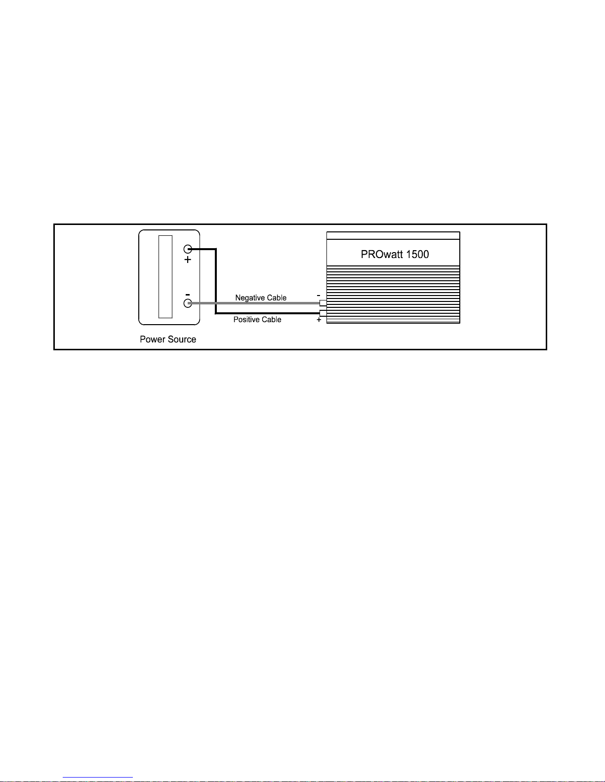
Figure 3. Connections to the PROwatt 1500
3.4 Connections
Follow the connection sequence described below.
STEP 1 Ensure that the ON/OFF switch on the PROwatt 1500 is in the OFF position. If the power source is a DC
power supply, switch it off as well.
STEP 2 Connect the cables to the power input terminals on the rear panel of the PROwatt 1500. The red terminal
is positive (+) and the white terminal is negative (-). Insert the bare ends of the cables into the terminals
and tighten the screws to clamp the wires securely.
STEP 3 Connect the cable from the negative (white) terminal of the PROwatt 1500 to the negative terminal of the
power source. Make a secure connection.
CAUTION! Loosely tightened connectors result in excessive voltage drop and may cause overheated wires
and melted insulation.
STEP 4 Before proceeding further, carefully check that the cable you have just connected connects the negative
terminal of the PROwatt 1500 to the negative output terminal of the power source. Power connections
to the PROwatt 1500 must be positive to positive and negative to negative.
CAUTION! Reverse polarity connection (positive to negative) will blow the fuses in the PROwatt 1500 and
may permanently damage the PROwatt 1500. Damage caused by reverse polarity connection is not covered by your warranty.
STEP 5 Connect the cable from the positive (red) terminal of the PROwatt 1500 to the positive terminal of the
power source. Make a secure connection.
5

WARNING! You may observe a spark when you make this connection since current may flow to charge capacitors in the PROwatt 1500. Do not make this connection in the presence of flammable fumes. Explosion or
fire may result.
STEP 6 If you are using a DC power supply as the power source, switch it on. Set the ON/OFF switch on the
PROwatt 1500 to the ON position. Check the meters and indicators on the front panel of the PROwatt
1500. The voltage bar graph should indicate 11 to 14 volts (22-28 volts for PW1500/24), depending on
the voltage of the power source. If it does not, check your power source and the connections to the
PROwatt 1500. The other indicators should be off.
STEP 7 Set the PROwatt 1500 ON/OFF switch to the OFF position. The indicator lights may blink and the inter-
nal alarm may sound momentarily. This is normal. Plug the test load into the AC receptacle on the
front panel of the PROwatt 1500. Leave the test load switched off.
STEP 8 Set the PROwatt 1500 ON/OFF switch to the ON position and turn the test load on. The PROwatt 1500
should supply power to the load. If it does not, refer to the troubleshooting section of this manual. If
you plan to measure the output voltage of the PROwatt 1500, refer to Section 2.2 of this manual.
4 Installation
4.1 Where to Install The PROwatt 1500 should be installed in a location that meets the following requirements:
a) Dry - do not allow water to drip or splash on the PROwatt 1500.
b) Cool - ambient air temperature should be between 0
ter.
c) Ventilated - allow at least 1 inch (2.5cm) of clearance around the PROwatt 1500 for air flow. Ensure
that ventilation openings on the rear and bottom of the unit are not obstructed.
d) Safe - do not install the PROwatt in the same compartment as batteries or in any compartment capable
of storing flammable liquids such as gasoline.
e) Close to Battery - install as close to the battery as possible in order to minimize the length of cable re-
quired to connect the inverter to the battery. It is better and cheaper to run longer AC wires than
longer DC cables.
CAUTION! To prevent fire, do not cover or obstruct ventilation openings. Do not install the PROwatt
1500 in a zero-clearance compartment. Overheating may result.
WARNING! This equipment contains components which tend to produce arcs or sparks. To prevent fire
or explosion do not install in compartments containing batteries or flammable materials or in locations
which require ignition protected equipment.
Mount the PROwatt on a flat surface using the mounting bracket on the bottom. Mounting hardware should be
corrosion resistant and #10 or larger. The PROwatt may be mounted horizontally or vertically.
4.2 Battery
o
C and 40o C (30o F and 105o F) the cooler the bet-
6
 Loading...