

Stat Fax 303 Plus Operator's Manual
Copyright 2001 Doc 303 Revised 04/2007 Rev. J
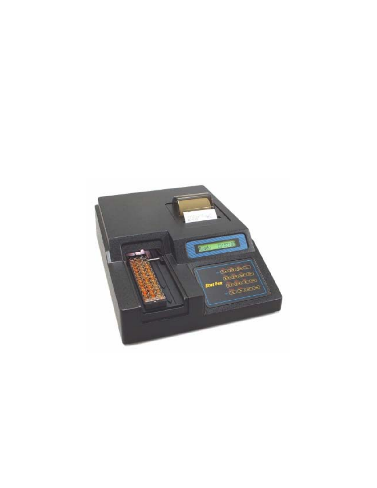
Stat Fax® 303 Plus
Operator’s Manual


TABLE OF CONTENTS
1.0 Introduction........................................................................................................................................... 1
1.1 Applications ...................................................................................................................................... 1
1.1.1 Intended Use .............................................................................................................................. 1
1.1.2 Summary of the Instrument ....................................................................................................... 1
1.2 Principles of Operation ..................................................................................................................... 2
1.3 Warning Markings ............................................................................................................................ 3
1.3.1 Safety Symbols .......................................................................................................................... 3
1.3.2 Safety Terms .............................................................................................................................. 3
1.4 Safety Precautions............................................................................................................................. 4
1.5 Installation......................................................................................................................................... 6
1.5.1 General Installation.................................................................................................................... 6
1.5.2 Serial Port................................................................................................................................... 7
1.5.3 Internal Printer ........................................................................................................................... 8
1.5.4 Check-out Procedure.................................................................................................................. 8
1.6 Major Parts and Controls .................................................................................................................. 9
1.7 Keyboard Functions........................................................................................................................ 10
1.8 Specifications.................................................................................................................................. 12
2.0 Operating Procedures.......................................................................................................................... 15
2.1 General Selections .......................................................................................................................... 15
2.1.1 Selecting a Strip Format........................................................................................................... 16
2.1.2 Selecting a Mode...................................................................................................................... 17
2.1.3 Quitting a Mode ....................................................................................................................... 18
2.1.4 Selecting Filters ....................................................................................................................... 18
2.1.5 Selecting a Blank ..................................................................................................................... 19
2.1.6 Selecting Duplicates................................................................................................................. 19
2.1.7 Unit Codes ............................................................................................................................... 20
2.1.8 Selecting Cutoff Interpretations............................................................................................... 20
2.1.9 Selecting Control Options........................................................................................................ 21
2.1.10 Selecting an END location..................................................................................................... 22
2.1.11 Strip Carrier Loading and Positioning ................................................................................... 22
2.2 Calculation Programs...................................................................................................................... 23
2.2.1 Absorbance Mode .................................................................................................................... 23
2.2.2 Calibrator (Single Standard) Mode.......................................................................................... 23
2.2.3 Cutoff Mode............................................................................................................................. 24
2.2.4 Cutoff Control Mode (C/O Control)........................................................................................ 26
2.2.4 Regression Mode ..................................................................................................................... 28
2.2.6 Point-to-Point Mode................................................................................................................. 30
2.2.7 % Absorbance Multi-Point Mode ............................................................................................ 31
2.2.8 Uptake Mode............................................................................................................................ 32
2.3 User Test Menu............................................................................................................................... 32
2.3.1 Storing a Test ........................................................................................................................... 32
2.3.2 Deleting a Test ......................................................................................................................... 33
2.3.3 Recalling a Test........................................................................................................................ 33

2.4 Special Features .............................................................................................................................. 34
2.4.1 Clock and Calendar.................................................................................................................. 34
2.4.2 Lamp Saver .............................................................................................................................. 34
2.4.3 Flags and Error Messages ........................................................................................................ 34
2.4.4 Differential Absorbances ......................................................................................................... 35
2.4.5 Calibration and Linearity ......................................................................................................... 36
3.0 Additional Tips and Information ........................................................................................................ 37
3.1 Restoring Electronic Calibration..................................................................................................... 37
3.2 Operating Precautions..................................................................................................................... 37
3.3 Maintenance.................................................................................................................................... 38
3.4 Troubleshooting .............................................................................................................................. 39
3.5 References....................................................................................................................................... 41
4.0 Appendices.......................................................................................................................................... 43
4.1 Appendix 1: Dri-Dye® Check Strips.............................................................................................. 44
4.2 Appendix 2: Test Log ..................................................................................................................... 45
4.3 Appendix 3: Sample Printouts ........................................................................................................ 46
4.4 Appendix 4: Contact Information ................................................................................................... 48

Awareness Technology, Inc. Stat Fax 303 Plus Operator’s Manual Rev. J 1
1.0 INTRODUCTION
1.1 Applications
1.1.1 Intended Use
This microstrip reader is a laboratory instrument intended for in-vitro diagnostic use. It is a
compact, microprocessor-controlled, photometer system designed to read and calculate the
results of endpoint colorimetric assays, which are read in microtiter strips. This general purpose
instrument is intended to be used by trained laboratory professionals.
1.1.2 Summary of the Instrument
The instrument reads monochromatically or bichromatically, and has 3 models; a four filter model
(405, 450, 492, and 630 nm), a six-filter UV model (405,450,492,630,545, and 340nm), and a 6filter VIS model (405,450,492,630,600, and 545 nm). Substitute wavelengths in the range of 340
nm to 700 nm are also available on specially ordered models. It is designed to accept many
single column microstrips up to 12 wells in length, as well as break-apart wells, whether the wells
have flat- or round bottoms. An accessory carrier is available for use with dual column 2x8-well
strips and single-column 8 well strips. The user need only position the carrier to the desired row;
the instrument automatically positions the strips, reads absorbances, calculates concentrations,
and prints results. It comes with a built-in thermal graphics printer with the capability to plot
standard curves.
Besides providing absorbance readings, this instrument also offers pre-programmed modes for
performing the most commonly used calculations, multiple convenience features, and user
programmable memory to further facilitate testing.
Preprogrammed Modes
The reader is programmed with many keyboard-selectable general purpose programs. Each
mode is self-prompting, to reduce error and simplify operation. The general purpose programs
include absorbance, single point calibration, cutoff determination, multi-point linear and log-logit
regressions and point-to-point connections, multi-point % absorbance calculations, and an
uptake mode. Each mode is described in detail in section 2.2-Calculation Programs. These
calculation modes have been selected to facilitate the performance of enzyme immuno assays,
drug levels, and other similar tests.
Convenience Features
Multiple convenience features include automatic blanking options and the ability to indicate the
locations of positive and negative controls and to enter control acceptance criteria for automatic
comparisons, to select positive and negative interpretations based on concentration value, and
to edit out discrepant duplicates with automatic reread and recalculation. Instructions for each of
these modes and convenience features are provided in this manual.

2 Stat Fax 303 Plus Operator’s Manual Rev. J
Awareness Technology, Inc.
User Programmable Memory
User-programmable memory allows the operator to store test protocols, recall tests by number,
and delete unwanted tests from a user-generated test menu. Instructions for using this memory
are given in section 2.3.3-Recalling a Test.
Besides quick, accurate, and reproducible results, the instrument offers maintenance-free and
easy operation, versatility, and economy. A stable factory-calibrated durable design, with a timed
lamp saving feature, further assures the reliability of this instrument.
1.2 Principles of Operation
Light energy from an overhead lamp is focused by a lens, directed through an aperture, and then
passed vertically through the sample. Below the sample, a continuously rotating wheel positions
the filters so that readings can be taken very quickly at both the primary and differential
wavelengths. Use of bichromatic differential absorbance values corrects for optical imperfections
in the plastic wells, differences in well meniscus, turbidity, and lamp variation. A photo detector
converts transmitted light energy into electrical signals, which are amplified and interpreted.

4 Stat Fax 303 Plus Operator’s Manual Rev. J
Awareness Technology, Inc.
1.4 Safety Precautions
To assure operator safety and prolong the life of your instrument, carefully follow all instructions
outlined below.
Read Instructions
Review the following safety precautions to avoid injury and prevent damage to this instrument or
any products connected to it. To avoid potential hazards, use this instrument only as specified.
For best results, familiarize yourself with the instrument and its capabilities before attempting any
clinical diagnostic tests. Refer any questions to your instrument service provider.
Servicing
There are no user-serviceable parts inside the instrument. Refer servicing to qualified service
personnel. Use only factory authorized parts. Failure to do so may void the warranty.
Personal Protective Equipment
Many diagnostic assays utilize materials which are potentially biohazardous. Always wear
protective apparel and eye protection while using this instrument.
Follow Operating Instructions
Do not use the instrument in a manner not specified by the manual or the protection provided by
the instrument may be impaired.
Use Proper Power Cord
Use only the power cord specified for this product and certified for the country of use.
Ground the Product
This product is grounded through the grounding conductor of the power cord. To avoid electric
shock, the grounding conductor must be connected to earth ground. An alternate method is to
attach a ground strap from the external grounding terminal on the rear panel of the instrument to
a suitable ground such as to a grounded pipe or some metal surface to earth ground.
Observe All Terminal Ratings
To avoid fire or shock hazard, observe all ratings and markings on the instrument. Consult this
manual for further ratings information before making connections to the instrument.
Install as Directed
The Microstrip Reader should be installed on a sturdy, level surface capable of supporting the
instrument’s weight of 13 lbs (5.9 kg) safely for safety and ventilation purposes. The mounting
surface should be free of vibrations.
Provide Proper Ventilation
Refer to the installation instructions for details on installing the product so it has proper
ventilation. The instrument should be surrounded by the following clearances: 8 cm around
perimeter of unit and 8 cm on top.
Do Not Operate Without Covers
Do not operate this instrument with covers and panels removed.


6 Stat Fax 303 Plus Operator’s Manual Rev. J
Awareness Technology, Inc.
1.5 Installation
1.5.1 General Installation
Unpack Instrument
Carefully unpack the instrument, removing it from its plastic bag. Report any damage to your
freight carrier at once. The box should also contain the Owner’s Manual and a serial cable.
NOTE: Retain the original packing material for future use in the event that the instrument is
shipped to another location or returned for service.
Instrument Mounting and Use
Place the instrument on a flat working surface capable of safely supporting the weight of the
instrument (approx. 21 lbs, 9.5 kg). Excessive vibration during reading may cause poor
repeatability; thus, a sturdy working surface is required. A clearance of at least 3 inches (8cm)
around the instrument is required to assure optimal ventilation. It is recommended that the
instrument be operated within an ambient temperature range of 18-35°C and humidity of less
than 80%.
Power Switch Position
When installing the power cord or if changing the setting on the voltage select switch the unit
should be turned off. Look at the rear panel of the instrument to check that the power switch is
in the Off position.
Power Cord Requirements
Use only the power cord specified for this product and certified for the country of use. For 110120 V units used inside the US use a UL listed cord set consisting of a minimum 18 AWG, Type
SVT or SJT three conductor cord, maximum 3 meters (10 feet) in length, rated 10 A, 125 V, with
a parallel blade, grounding type attachment plug.
For 220-240 V units used inside the US use a UL listed cord as above, except rated 250 V, with
a tandem blade, grounding type attachment plug. The cord set provided by the manufacturer
meets these requirements.
Safety Grounding
Do not alter or defeat the safety grounding methods provided. To avoid the risk of electric shock,
the third prong of the AC power plug must be connected to conductive parts internal to the
equipment. Internal fasteners to grounding points are marked by the IEC 417 symbol 5019
. DO NOT loosen or remove these fasteners or connections. An alternate method of
grounding is provided by connecting the grounding terminal located on the rear panel, to a
suitable ground.
To avoid electric shock, the power cord protection ground conductor must be connected to
ground.

Awareness Technology, Inc. Stat Fax 303 Plus Operator’s Manual Rev. J 7
Voltage Select Switch
Locate the voltage select switch on the rear panel. This is a 2-position slide switch that will
configure the instrument to accept either 230V or 115V input. Do not connect equipment to the
power supply before changing the line voltage selection switch.
Warning: To prevent permanent damage to the instrument, this switch must be set
for the appropriate input voltage before powering up.
When you can see the 230V label, the instrument is set for 230V input. If you plug the
instrument into an 115V power supply while 230V is selected, the instrument will have
insufficient operating power.
To select 115V input, insert a straight screwdriver blade (or similar instrument) into the slot on
the switch, and slide it into its alternate position. Upon sliding the switch, you will see the 115V
label appear.
Warning: If the instrument is configured to accept 115V and you plug it into a 230V
power supply, the fuses will blow and permanent damage to the electronics may result.
Assure Clean Power Availability
The circuit used should be substantially free of large voltage transients (Kilovolt amp loads) such
as large pumps, large centrifuges, refrigerators and freezers, air conditioners, large autoclaves,
ovens, and dryers. The instrument may fail to operate normally if the power supply is
interrupted. If this occurs, turn the instrument off for a moment. When you turn the instrument
back on, it will resume normal operation, but a standard curve which was not stored in
nonvolatile memory will be lost.
Fuse Requirements
The fuses are located internally in the instrument; there are two fuses, fusing both sides of the
main power supply. Fuse failure is a very rare occurrence and should indicate malfunction of the
equipment requiring service by qualified personnel.
The fuses used within this instrument are 1/2 Amp T rated (slow blow), 250 V. Cartridge size is
3AG or size “0”, dimensions 1/4 x 1-1/4” (6.3 x 32 mm). For continued protection against risk of
fire, use the same fuse for either 115 or 230 V line voltage selection. Disconnect power cord
from mains supply before replacing fuses.
1.5.2 Serial Port
The serial port on the back of the instrument echoes the data shown on the internal printer,
except for data printed in graphical mode (i.e., standard curve plots). You may use the serial
port with the strip reader to output to a PC, but this will require a cable and software not provided
with the reader. Contact your dealer for the appropriate cable. Remember that the microstrip
reader only sends data out. It does not accept any input from the external equipment.
The serial connector of the reader is located on the right side of the rear panel. Interface: “DB9P” is configured for data terminal equipment (“D” connector with 9 male pin contacts.) Pin 1 is
ground, Pin 2 is the transmit data output.

8 Stat Fax 303 Plus Operator’s Manual Rev. J
Awareness Technology, Inc.
Data is transmitted at 2400 baud, with 1 start bit, 1 stop bit, 8 data bits in ASCII Code, and no
parity bit (RS-232 signal levels).
With both the reader and the receiving equipment turned off, plug in both ends of the cable.
Then turn the receiving equipment on. Finally, turn on the strip reader. It is important to have the
receiving equipment ready before starting up the strip reader so that data will not be lost.
1.5.3 Internal Printer
If there is no paper in the printer, install a new roll of paper as follows:
How to install a roll of paper:
Remove the paper cover by pinching its sides together and pulling up. Unroll about 10 inches
(25cm) of paper, and place the roll on the table behind the instrument. A ragged edge or
wrinkled paper will be difficult to load and could cause a paper jam. Feed a clean cut edge of the
paper from the back, into the printer, along the top edge of the metal guide inside the printer
paper well. Feed slightly more than 1 inch (3 cm) of paper in, then press the PAPER key several
times to automatically feed the paper through the printer. You will see the paper feed up through
the paper slot in front. If you have difficulty, cut a new straight edge before trying again. Drop the
roll of paper into the printer paper well in back, spooling up any loose paper. Replace the paper
cover by pinching its sides together and placing it down over the roll of paper. Use of the paper
cover is optional for holding the paper down into the printer paper well.
1.5.4 Check-out Procedure
After installation and each time you start up the instrument, perform the following instrument
checkout procedure. If any portion of the procedure does not check out properly, contact your
dealer to arrange for assistance.
Turn the power switch on. The printer should print the instrument name and “:X,” where X is the
software revision level. Then the time and date will print. If they are not correct, see section
2.4.1, Clock and Calendar, for setting time and date. Look for “Ready” and the correct time in the
display. Press the ABS key. Look into the strip track for light, indicating that the lamp is lit. See
“ABSORBANCE MODE” displayed and printed. The instrument will then display “SELECT
FILTER”. Select 405-630nm. Then see “Set Carrier” in the display. Now load the empty carrier
over the carrier bar and press the BLANK key and the ENTER key. The instrument will read air.
Check that the carrier moves in and back out of the instrument. Check that all 8 or 12 of the
readings are 0.000 ± 0.005A. Poor repeatability of the absorbance readings for air indicates
possible electronic problems.
Awareness Technology, Inc. Stat Fax 303 Plus Operator’s Manual Rev. J 9
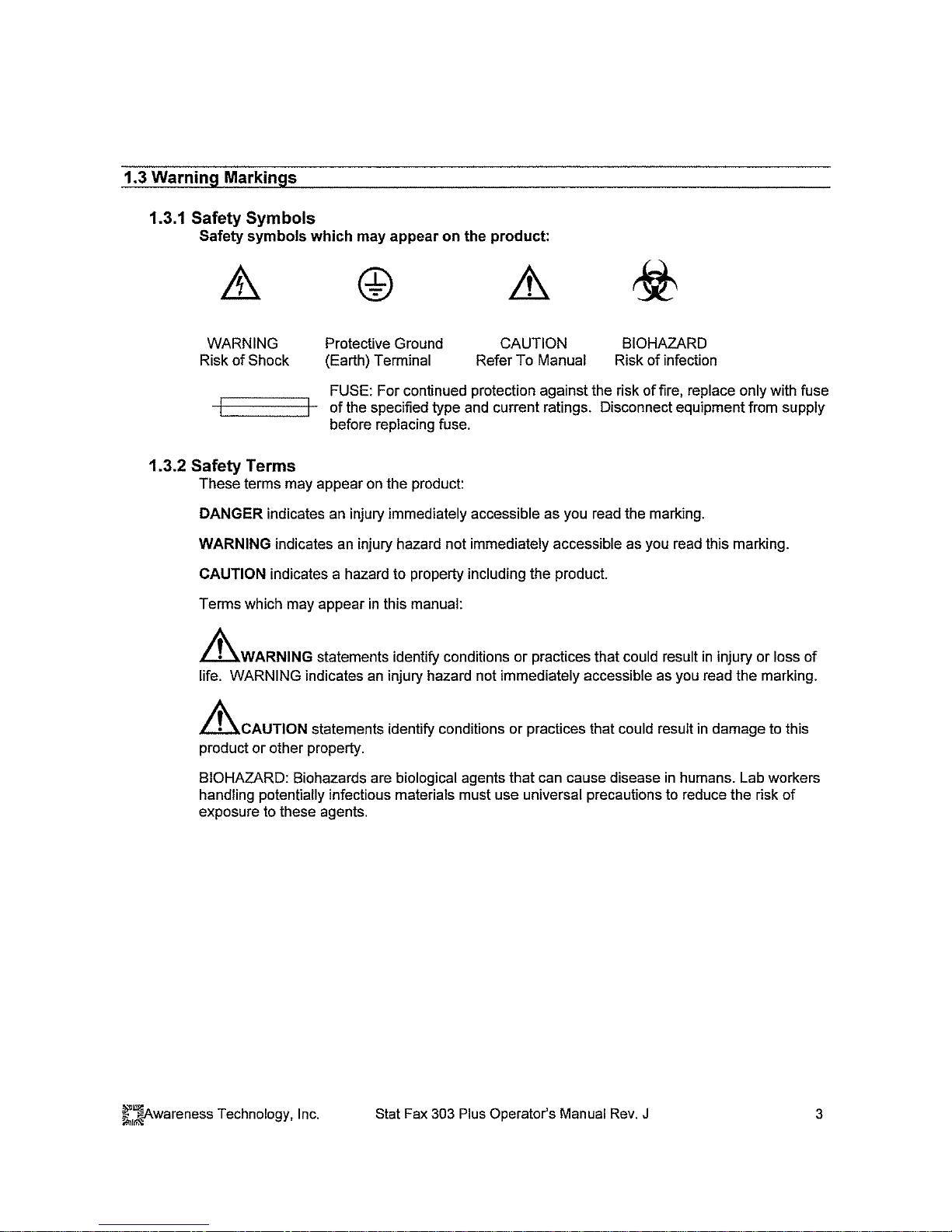
1.6 Major Parts and Controls
The following labeled sketches will help you to locate and identify the major parts of the
microstrip reader. More details on the operation of each feature are provided in section 2,
Operating Procedures. The voltage select switch is on the base. The power switch and serial
connector are on the rear panel.
Cover
Optical system
(under cover)
Printer paper well
(with paper roll cover)
Printer paper slot
Alpha-numeric display
Carrier track
(with carrier)
Keyboard
Place carrier groove
over bar
10 Stat Fax 303 Plus Operator’s Manual Rev. J
Awareness Technology, Inc.
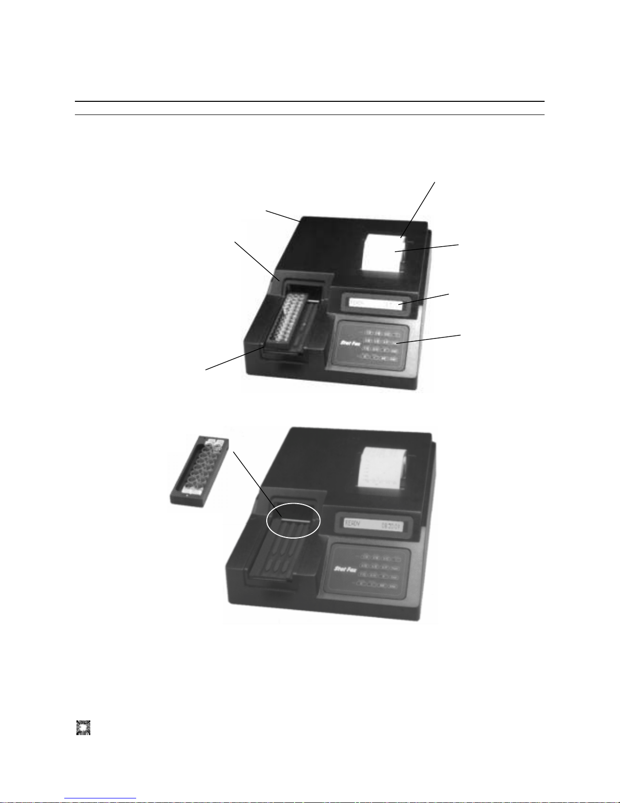
1.7 Keyboard Functions
T
h
e
B
L
A
N
K
The numeral keys serve several functions. As numbers, they are used to enter test parameters,
and to make filter selections. Any key serving multiple functions will respond to the displayed
request for information.
ABS, STND, CUT, MULT, %ABS, and UPT, are the keys used to select a mode of operation.
ABS stands for Absorbance Mode.
STND stands for Calibrator (Single Standard) Mode.
CUT stands for Cutoff Mode and offers two choices: Cutoff Control, and Cutoff mode with
Reverse Cutoff option.
MULT stands for Multi-Standard Mode and offers two choices: regression (including linear, log,
and log-logit), and point-to-point connection.
%ABS stands for Percent Absorbance Multi-Point Mode.
UPT stands for Uptake Mode.
Pressing the INTRP key causes the reader to ask for positive and negative cutoff points to be
used for automatic sample interpretation.
Pressing the CNTRL key causes the reader to ask for the locations and acceptance criteria of
high and low controls to be used for automatic labeling.
The ENTER key is used to tell the instrument when
The AUX key is used to turn the lamp on and off.
The CLEAR key is used to erase a typing error
when information is being entered by keyboard.
Pressin
g
twice quits the mode.
The PAPER key advances the printer paper
f
orward one
line
each time it is pressed
.
The ALT key is used to enter a negative sign and
to access a list of alternate functions such as
saving and deleting tests, setting the clock, and
choosing 8 o
r 12 well strips.
The MENU key is used to access tests stored in the It is
also used to enter a decimal point for numeric entries.
The BLANK key allows automatic blank
on well A-1 in the ABS Mode.

Awareness Technology, Inc. Stat Fax 303 Plus Operator’s Manual Rev. J 11
The END key allows the user to select the total number of wells to read and print.
The key assignments for the filters are as follows:
For all models: key 1 is 405nm, key 2 is 450nm, key 3 is 492nm, key 4 is 630nm
6 filter UV: key 5 is 545nm, key 6 is 340nm
6 filter VIS: key 5 is 600nm, key 6 is 545nm
The 1 and 0 keys are also used to answer YES and NO questions.

12 Stat Fax 303 Plus Operator’s Manual Rev. J
Awareness Technology, Inc.
1.8 Specifications
Photometric
Linear Measurement Range ......................0.00 to 3.0 Absorbance Units (A)
Photometric Accuracy ................................± (1% of the reading + 0.01 A) from 0 to 1.5A
................................................................... ± (2% of the reading + 0.01 A) from 1.5 to 3.0A
Stability ......................................................Drift of no more than 0.005A in 8 hours
Warm up Time ...........................................45 seconds, built-in
Light Source...............................................Tungsten Lamp
Standard Wavelengths...............................Standard: 405, 450, 492, 630nm
Six Filter UV: 405, 450, 492, 630, 545, and 340 nm
Six Filter VIS: 405, 450, 492, 630, 600, and 545 nm
Type of Filter ..............................................3-cavity hard coat interference filter, 10nm half band
pass typical
Vessel ........................................................Single, double, or break apart strips, up to 12 wells
long,
3 strip loading capacity
Electronic and Software
Speed ........................................................Reads, calculates and prints results for up to 12 wells
in about 30 seconds
Display .......................................................LCD, 16” characters, 5x7 dot matrix
Internal Printer ...........................................Thermal, dot matrix, 20 characters per line
Keyboard ...................................................16-key, membrane switch, 4X4
Calculation Modes .....................................Single point calibration, Multi-point calibration with
regression or point-to-point curve fit, cutoff, cutoff
control, % Absorbance Multi-Point, Uptake.
Serial Port ..................................................Output only, 2400 Baud, 1 start bit, 8 data, 1 stop, no
parity, no handshake
Power Source ............................................Switch selectable power supply (115V or 230V
indicated)
Voltage Source 110-120/220-240 VAC from 50 to 60
Hz, CAT II
Power consumption is less than 50 Watts
Fuse: two 1/2A, T rating, 250V, 3AG type fuse
All power cords must be approved for the country of
use
Certifications and Compliances .............NRTL Listed Standard UL -61010A-1, Electrical
Equipment for Laboratory Use.
CE Certificate of Conformity. Conforms to the
following standards: EN 61010-1, EN 61326, following
the provisions of the 98/79/EC IVD directive
Physical
Enclosure...................................................ABS Plastic cover with metal base
Dimensions .............................................Approx. 9”x 12” x 3”, (23 x 30 x 8 cm) 13 lbs (5.9 Kg)
 Loading...