

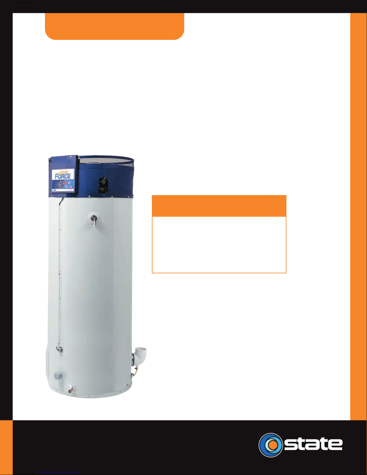
State Water Heaters Utra-Force STC-077, Utra-Force SUF100 150NE, Utra-Force SUF100 199NE, Utra-Force SUF100 240NE Service Handbook
Page 1
� � � � �� � �� � � � � � � �
� ���� �� � �� �
� � � � � ���� ��� � � �� � ����� � � ����
� ��� �� � � ��� � �� � ��� ������� ���� � � �
� �� � ��� � �� �� � � ��� ��� � ����
�
� � � � � � � � � � � � � �
� � � � � � �� � � � �
� � � � � � �� � � � �
� � � � � � �� � � � �
� �� � ��� � �� � � � �� � ����� ����
� � ���� � � � � ��� � � �� � �
� � � ���� ��� �� � ��� ��� � �� �� �� ����� � � �
COMMERCIAL
The Expert’s Choice®
Page 2

SUF Service Handbook
TABLE OF CONTENTS
STC-077
Introduction . . . . . . . . . . . . . . . . . . . 2
Installation
Clearances. . . . . . . . . . . . . . . . . . . . . 3
Gas Requirements . . . . . . . . . . . . . . . 3
Venting . . . . . . . . . . . . . . . . . . . . . 4 – 8
Air Requirements . . . . . . . . . . . . 9 – 11
Contaminated Air . . . . . . . . . . . . . . . 12
Flammable Items . . . . . . . . . . . . . . . 12
Multiple Unit Piping. . . . . . . . . . . . . . 13
Condensation. . . . . . . . . . . . . . . . . . 14
Operation
Sequence of Operation . . . . . . . . . . 15
Controls . . . . . . . . . . . . . . . . . . . . . . 16
Circuit Boards. . . . . . . . . . . . . . . . . . 17
Troubleshooting
Pre-Service. . . . . . . . . . . . . . . . . . . . 18
120 VAC to Control. . . . . . . . . . . . . . 18
Transformer . . . . . . . . . . . . . . . 19 – 20
ECO Check . . . . . . . . . . . . . . . 21 – 22
Temperature Probe. . . . . . . . . . . . . . 23
Pressure Switch Continuity . . . . . . . 24
Troubleshooting (continued)
Blower . . . . . . . . . . . . . . . . . . . . . . . 25
Pressure Switch Performance . 26 – 27
120 VAC to Ignitor . . . . . . . . . . . . . . 28
Ignitor Resistance. . . . . . . . . . . . . . . 29
Gas Valve Test . . . . . . . . . . . . . . . . . 30
Gas Pressure Check . . . . . . . . . . . . 31
Component Information
Orifice Tables . . . . . . . . . . . . . . . . . . 32
Pressure Switches . . . . . . . . . . 33 – 34
Wiring Diagrams . . . . . . . . . . . . . . 35
Service Aids . . . . . . . . . . . . . . . . . . 36
SUF Muffler . . . . . . . . . . . . . . . . . . . 37
Questions & Answers . . . . . . . . . . 38
Error Codes. . . . . . . . . . . . . . . . . . . 39
Service Checklist . . . . . . . . . . . . . . 40
Parts Lists
Models 100 – 150, 100 – 199,
and 100 – 240 . . . . . . . . . . . 41 – 43
Page 3

SUF SERVICE HANDBOOK
INTRODUCTION
INTRODUCTION
This service handbook is designed to aid in servicing and troubleshooting State SUF 150, 199 and 240 water heaters.
No duplication or reproduction of this book may be made without the express written authorization of the State Water
Heaters Company.
The following text and illustrations will provide you with a step by step procedure to verify proper installation, operation
and troubleshooting procedures. Additional quick reference data is included to assist you in servicing this product.
The information contained in this handbook is designed to answer commonly faced situations encountered in the operation of the SUF product line and is not meant to be all inclusive. If you are experiencing a problem not covered in this
handbook, please contact the S t ate Technical Information Dep artment a t 1-800-3 65-0577 or you r local State Representative for further assistance. This handbook is intended for use by licensed plumbing professionals and reference
should be made to the instruction manual accompanying the product. This handbook contains supplemental information to the SUF instruction manual.
Qualifications: Installation or service of this water heater requires ability equivalent to that of a licens ed tradesman in
the field involved. Plumbing, venting, gas supply and electrical testing skills are required.
Tools Required:
• Phillips head and flat tip screw drivers
• Set of marked drill bits
• Electric multimeter tester
• Gas pressure gauge or manometer (gauge — part number 8099-2)
• Water pressure gauge (part number 4798)
• Digital manometer or draft gauge
• Thermometer (part number 4870 — range 0 thru 220°F)
1
•
/2”, 1” and 11/8” sockets
• Pipe wrench for union disconnect
NOTE Also, have a copy of the instruction manual for the model and series SUF that you are servicing.
Technical Training Department State Water Heaters
STC-077
2 Ashland City, Tennessee © 2004
Page 4
SUF SERVICE HANDBOOK
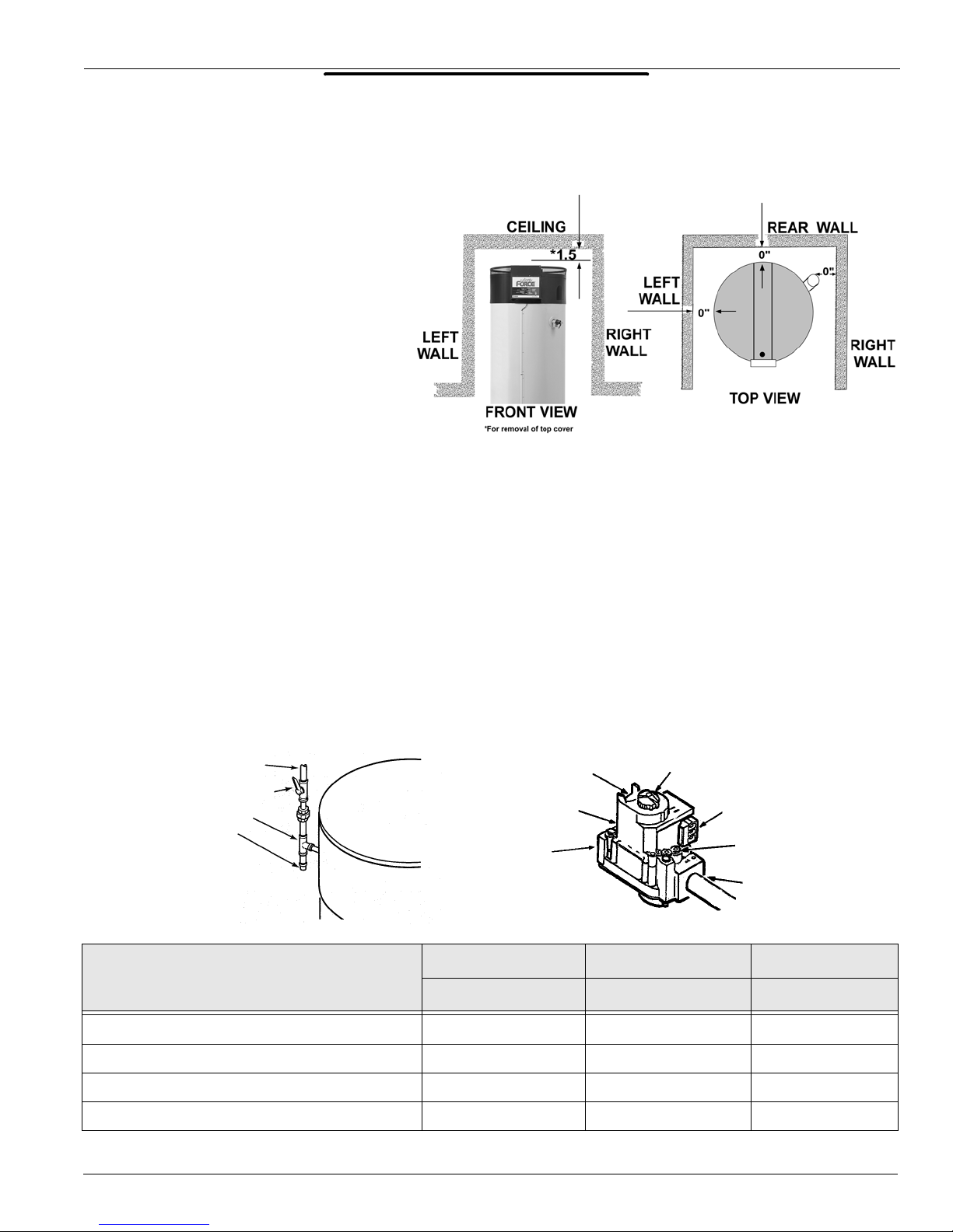
INSTALLATION
INSTALLATION
This portion of the handbook will review
often overlooked installation requirements. The installation manual covers
these items in detail. SUF water heaters
are approved for installation on combustible flooring. The minimum clearance to combustibles or noncombustibles is 0 inches from the sides
and rear, 0 inches from vent piping, and
1.5 inches from the top cover. A 24 inch
clearance for all serviceable parts is
recommended. Clearances may vary
between SUF models. See installation
manual or the label on the heater for
your specific model.
CLEARANCES
GAS REQUIREMENTS
NOTE: Pressure without capacity will result in lockout. Follow the piping guidelines in the
installation manual. The supply gas pressure is normally measured at the dirt leg or at the inlet gas
pressure tap on the gas valve. This reading must be measured with ‘flowing’ gas.
The manifold gas pressure is measured at the manifold pressure tap on the gas valve when the
gas is flowing. The gas valves used on all SUF water heaters are 24 VAC combination step opening gas valves. They incorporate the main valve and pressure regulator into one body.
REGULATED GAS SUPPLY LINE
MAIN GAS
SHUTOFF VALVE
DIRT LEG TEE
PIPE CAP
GAS SUPPLY SPECIFICATIONS
NATURAL GAS NATURAL GAS PROPANE GAS
PRESSURE REGULATOR
ADJUSTMENT
(COVER SCREW)
INLET PRESSURE
TAP
GAS INLET
SUF 240 SUF 150 & 199 SUF 150 & 199
GAS VALVE ON/OFF
TH & TR TERMINALS
(MAIN VALVE)
MANIFOLD
PRESSURE TAP
GAS OUTLET
Max
. Gas Supply Pressure Inches W.C.
Nominal Gas Supply Pressure
Minimal Gas Supply Pressure
Manifold Pressure
State Water Heaters Technical Training Department
Ashland City, Tennessee © 2004
Inches
Inches
Inches
W.C.
W.C.
W.C.
12.0 (3 kPa) 12.0 (3 kPa) 14.0 (3.45 kPa)
7.0 (1.75 kPa) 7.0 (1.75 kPa) 11.0 (2.74 kPa)
5.5 (1.37 kPa) 4.5 (1.12 kPa) 11.0 (2.74 kPa)
4.0 (1 kPa) 3.5 (0.8 kPa) 10.0 (2.5 kPa)
3 STC-077
Page 5

SUF SERVICE HANDBOOK
INSTALLATION
VENTING
Equivalent Feet of Pipe Intake or Exhaust
VENT LENGTH TABLE
NUMBER OF 90°
ELBOWS
ONE (1)
TWO (2) 7 40 110
THREE (3) 7 35 105
FOUR (4) 7 30 100
FIVE (5) 7 -- 95
SIX (6) 7 -- 90
3” MINIMUM
PIPE (FEET)
745115
3” MAXIMUM
PIPE (FEET)
4” MAXIMUM
PIPE (FEET)
4-inch PVC may be used for a MAXIMUM intake of ONE HUNDRED TWENTY (120) EQUIV ALENT
FEET and a MAXIMUM exhaust of ONE HUNDRED TWENTY (120) EQUIVALENT FEET. The
maximum number of 90° elbows with the 4-inch venting is six (6) on the intake and six (6) on the
exhaust. A 90° elbow is equal to five (5) equivalent feet of pipe. One (1) 90° elbow is equal to two
(2) 45° elbows. Any venting configuration using less than 50 equivalent feet should use 3-inch venting. See Vent Length Table.
The 3-inch venting terminals (provided) must be used with the 4-inch venting by adding 4 x 3
reducing coupling at the venting terminals. A reducing coupling is also needed immediately after
the condensate elbow (exhaust) and immediately before the 3-inch blower adapter (intake) if direct
venting is installed. See Vent Length Table.
DIRECT VENTING
The air intake provided on the unit contains a mesh screen (see Figure below) to prevent large particles from entering the unit.
3” (7.6CM) 45° PVC ELBOW WITH MESH SCREEN
WARNING
WHEN THE UNIT IS TO
BE SETUP AS A DIRECT VENT, THE
MESH SCREEN MUST BE REMOVED.
THE INLET VENT PIPE MAY THEN BE
GLUED TO THE AIR INTAKE (see following Figure) PROVIDED ON THE UNIT.
Technical Training Department State Water Heaters
STC-077
4 Ashland City, Tennessee © 2004
Page 6
SUF SERVICE HANDBOOK
INSTALLATION
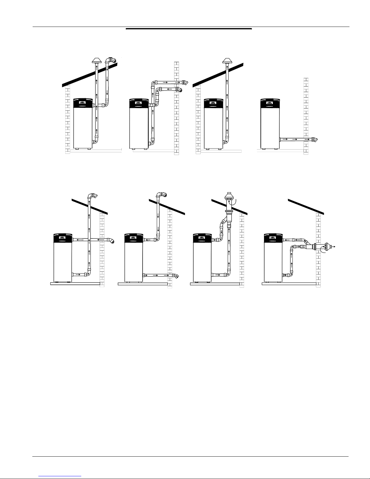
VENTING CONFIGURATIONS
SEALED DIRECT
VENT VERTICAL
SEALED DIRECT VENT
HORIZONTAL INTAKE
VERTICAL EXHAUST
SEALED DIRECT
VENT SIDEWALL
SEALED DIRECT VENT
VERTICAL INTAKE
HORIZONTAL EXHAUST
INDOOR CONVENTIONAL
VERTICAL
SEALED DIRECT VENT
W/ CONCENTRIC VENT
VERTICAL TERMINA-
INDOOR CONVENTIONAL
SIDEWALL
SEALED DIRECT VENT
W/ CONCENTRIC VENT
HORIZONTAL TERMINATION
VENTING MATERIALS
This unit can be vented using only PVC (Class 160, ASTM D-2241; Schedule 40, ASTM D-1785; or
Cellular Core Schedule 40 DWV, ASTM F-891), Schedule 40 CPVC (ATSM F-411), or ABS (ASTM
D-2661) pipe. The fittings, other than the TERMINATIONS should be equivalent to PVC-DWV fittings meeting ASTM D-2665 (Use CPVC fittings, ASTM F-438 for CPVC pipe and ABS fittings,
ASTM D-2661/3311 for ABS pipe. If CPVC or ABS pipe and fittings are used, then the proper
cement must be used for all joints, including joining the pipe to the Termination Tee (PVC Material).
PVC Materials should use ASTM D-2564 Grade Cement; CPVC Material should use ASTM F-493
Grade Cement and; ABS Materials should use ASTM D-2235 Grade Cement.
For water heaters in locations with high ambient temperatures (above 100°F) and/or insufficient
dilution air, it is recommended that CPVC or ABS pipe and fittings (MUST USE SUPPLIED VENT
TERMINAL) be used.
State Water Heaters Technical Training Department
Ashland City, Tennessee © 2004
5 STC-077
Page 7
SUF SERVICE HANDBOOK
INSTALLATION
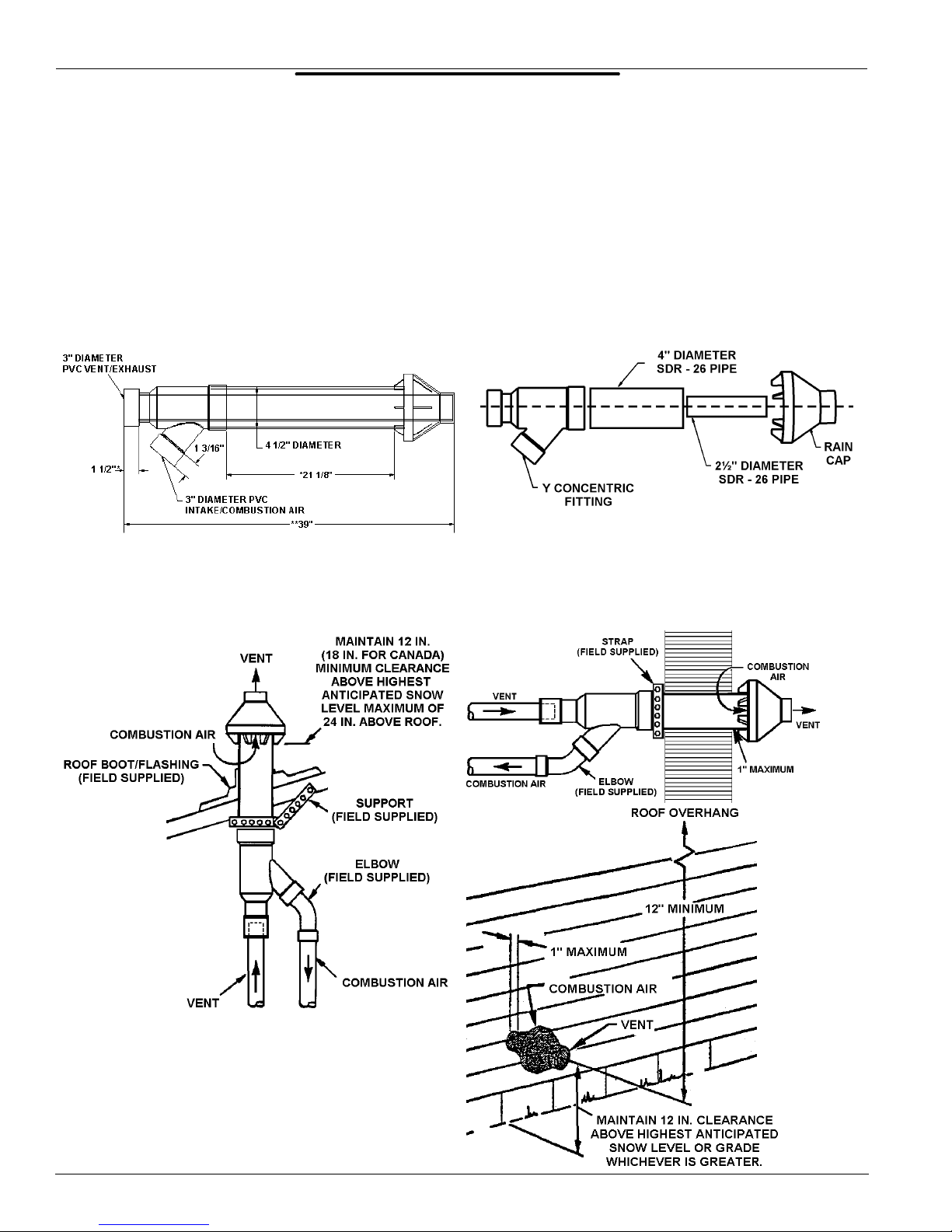
CONCENTRIC VENT TERMINATION
The concentric vent termination kit, Part No. 9003910005 can be used on SUF 150 – 240 Ultra
Force water heaters. It adds zero equivalent feet to the vent system. Below are some general application and installation guidelines for the concentric vent kit. Refer to the accompanying literature
and the water heater installation manual for complete venting installation instructions.
This concentric vent termination kit may be used with 3 or 4 in. diameter pipe systems. When connecting to a 4 in. diameter pipe system a 3 x 4 in. field supplied reducer is to be installed at the
intake and exhaust connection of the concentric vent termination kit. See water heater installation
and operation manual for venting specification
Dimension 211/8 in. may be lengthened to 60 in. maximum. Dimension 211/8 in. may also be shortened by cutting the pipes, provided in the kit, to 12 in. minimum. Dimension 39 will change accord-
ingly as dimension 211/8 in. is lengthened or shortened
Horizontal
Installation
Vertical Installation
Technical Training Department State Water Heaters
STC-077
6 Ashland City, Tennessee © 2004
Page 8

SUF SERVICE HANDBOOK
INSTALLATION
VENTING CLEARANCES
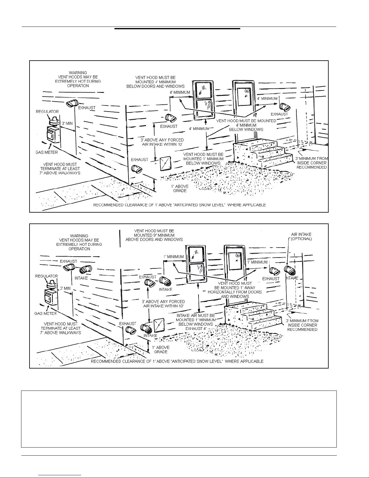
This illustrates the exterior clearances for these SUF units when installed as direct vent heaters.
NOTE: 24 inches between inlet and outlet is a MINIMUM. Greater distance is recommended.
In colder climates increasing the 24” minimum to a maximum practical distance will reduce the
possibility of frost over from side winds blowing exhaust vapors into the air intake.
SUF MODEL 150 – 199
SUF MODEL 240
State Water Heaters Technical Training Department
Ashland City, Tennessee © 2004
7 STC-077
Page 9
SUF SERVICE HANDBOOK
INSTALLATION
EXTERIOR SIDEWALL CLEARANCES
Horizontal Vent (Using Room Air for Combustion)
Horizontal Direct Vent (Using Outdoor Air for Combustion)
When multiple units are directly vented through a wall, all intake vent terminals must be no lower
than the highest exhaust vent terminal.
CAUTION
DO NOT TERMINATE THE VENTING WHERE NOISE FROM THE EXHAUST OR INTAKE WILL BE OBJECTIONABLE. THIS INCLUDES LOCATION CLOSE TO
OR ACROSS FROM WINDOWS AND DOORS. AVOID ANCHORING THE VENT AND
INTAKE PIPES DIRECTLY TO FRAMED WALLS, FLOORS OR CEILINGS UNLESS RUBBER ISOLATION PIPE HANGERS ARE USED. THIS PREVENTS ANY VIBRATIONS
FROM BEING TRANSMITTED INTO THE LIVING SPACES.
Technical Training Department State Water Heaters
STC-077
8 Ashland City, Tennessee © 2004
Page 10

SUF SERVICE HANDBOOK
INSTALLATION
AIR REQUIREMENTS
MINIMUM AIR FOR COMBUSTION
10 Cubic Feet of Air Per 1000 BTUH
Stoichiometric or theoretical complete combustion requires 10 cubic feet of air per 1000 BTUH of
gas input. The National Fuel Gas Code also recommends an additional 2.5 cu.ft. of “excess air”.
This 12.5 cu.ft. minimum supply air per 1000 BTUH input applies to natural and propane gas models.
The National Fuel Code also specifies minimum make-up air opening sizes for various building
installations (Ref: NFPA 54, ANSI Z223.1, sec 5.3).
MAKE-UP AIR
Direct Vent Installation
This model is approved for direct venting either horizontally or vertically or conventional venting
horizontal or vertical. Direct venting avoids using room air for combustion and eliminates the need
for additional air intake ducts.
State Water Heaters Technical Training Department
Ashland City, Tennessee © 2004
9 STC-077
Page 11
SUF SERVICE HANDBOOK
INSTALLATION
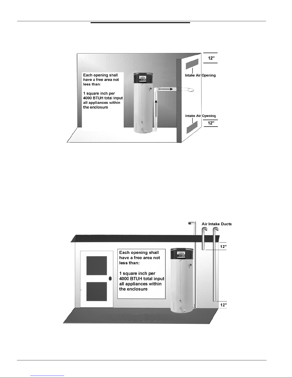
MAKE-UP AIR
Direct Communication
A fresh supply of make-up air for combustion can be supplied to the heater through make-up air
openings, which directly communicate with the out of doors. Two openings are required — one
within 12 inches of the top of the enclosure and one within 12 inches of the bottom of the enclosure.
Each opening shall have a free area of not less than 1 square inch per 4000 BTUH of the total input
of all appliances within the enclosure.
The lower opening is primarily providing combustion air. The upper opening is providing vent dilution air and acts as a relief opening for flue gases should the vent become obstructed or a down
draft condition occur.
MAKE-UP AIR
V ertical Ducts
Often it is more practical to install vertical make-up air ducts to the outdoors. Again, two openings
are required — within 12 inches (30 cm) of the top of the enclosure and one within 12 inches (30
cm) of the bottom of the enclosure. Each opening shall have a free area of not less than 1 square
inch per 4000 BTUH of the total input of all appliances within the enclosure.
Technical Training Department State Water Heaters
STC-077
10 Ashland City, Tennessee © 2004
Page 12

SUF SERVICE HANDBOOK
INSTALLATION
MAKE-UP AIR
Horizontal Ducts
When the heater is installed in an interior room with no roof access for vertical ducts, horizontal
make-up ducts should be installed. When using horizontal ducts, two openings are required —
within 12 inches (30 cm) of the top of the enclosure and one within 12 inches (30 cm) of the bottom
of the enclosure. Each opening shall have a free area of not less than 1 square inch per 2000
BTUH of the total input of all appliances within the enclosure.
INSUFFICIENT MAKE-UP AIR
Backdraft
Insufficient make-up air is a major cause of combustion problems. One common example is in a
restaurant installation where exhaust vent equipment was not considered in sizing make-up air
requirements. This may result in air being backdrafted by the restaurant exhaust equipment
through the heater causing flue gas spillage, flame roll out, improper combustion, inconsistent pilot
operation, and/or erratic heater shutdown.
A possible solution to this situation would be to use a SUF with direct venting.
A less common service issue associated with a backdraft or negative pressure room would be the
opening or closing of air pressure switches. This may result in erratic or no heater operation.
State Water Heaters Technical Training Department
Ashland City, Tennessee © 2004
11 STC-077
Page 13

SUF SERVICE HANDBOOK
INSTALLATION
CONTAMINATED AIR
RUST
=
CHIPS
Along with adequate make-up air, the quality of the air is import ant. Contaminants in combustion air
can lead to premature heater failure. Vapors from bleaches, soaps, salts, etc. are drawn into the
combustion chamber with the make-up air and, once fired, mix with water vapor in the gasses to
form extremely corrosive hydrochloric or hydrofluoric acid and other corrosive by-products. Dust
drawn in may build up on the blower or clog the main burner ports. Also, be certain to examine the
exterior area around the air intake of a direct vent installation for the contaminants.
FLAMMABLE ITEMS
Flammable items or pressurized containers or any other potentially hazardous articles must never
be placed on or adjacent to the heater. Open cont ainers of flammable material should not be stored
or used in the same room with the heater or in the area of the exterior air intake of a direct vent
installation. Direct venting does not eliminate the need to remove flammable or corrosives from the
area surrounding the heater.
Technical Training Department State Water Heaters
STC-077
12 Ashland City, Tennessee © 2004
Page 14

SUF SERVICE HANDBOOK
INSTALLATION
MULTIPLE UNIT — WATER PIPING
NOTES APPLY TO ALL SYSTEMS:
*ADD GATE VALVES TO INLET AND OUTLET OF EACH
UNIT FOR ISOLATION FLEXIBILITY. LOCATE AT THE
SAME POINT FROM TEE.
** ADD THERMAL EXPANSION TANK TO COLD WATER
SUPPLY IF NECESSARY.
CONDENSATION HOSE MUST BE ALLOWED TO DRAIN.
NOTE: T&P VALVES MUST BE PIPED TO OPEN DRAIN OR
PER LOCAL CODE
State Water Heaters Technical Training Department
Ashland City, Tennessee © 2004
13 STC-077
Page 15

SUF SERVICE HANDBOOK
INSTALLATION
CONDENSATION
The average dewpoint of natural gas flue products is 127° F. Propane flue products is 119° F. With
70° F ambient air temperature and 180° F stored water temperature, exhaust gas will be approximately 140° F. Recommended starting point for water storage is 120° F.
The extra high thermal efficiency of the SUF will result in condensation in the flue passage. The following answers common questions about this condensation.
CAN I DRAIN THIS CONDENSATION TO A FLOOR DRAIN? The “Corrosion Resistance of Cast
Iron Soil Pipe” by the Ductile Metals Association (formally the Cast Iron Soil Pipe Institute) states
that:
“Internal corrosion of cast iron soil pipe and fittings can be caused by strong acids or other reagents
having an acidity of pH 4.3 or less if allowed to contact cast iron pipe for an extended period of time
without sufficient dilution to raise the pH valve about 4.3. By avoiding low pH discharges, internal
corrosion problems can be limited or eliminated, assuring the owner many years of service.”
WHAT ABOUT THE pH VALUES OF CONDENSATE AND SODA POP? The pH of the SUF condensate average 4.5 which is approximately 4 times less concentrated than the limit of 4.3 recommended by the DMA. Any water flow in the drain rapidly dilutes the condensate even more. A can
of leading carbonated cola drink measured a pH of 2.5 which is 300 times more concentrated than
the SUF condensate.
WHAT DOES THE pH SCALE MEAN? The pH value is a measure of acidity of alkalinity. A pH of
7 is neutral. Numbers from 7 to 1 indicate increasing acidity and numbers from 7 to 14 indicate
increasing alkalinity. The pH scale is similar to the Richter scale used to measure earthquakes.
Each number indicates a change of 10 times the concentration of the previous value. A pH 6 is 10
times more concentrated than a pH 7, a pH 5 is (10x10) 100 times pH 7 and pH 4 is (10x10x10)
1,000 times pH 7, etc.
WHAT ABOUT CONDENSATE NEUTRALIZERS? Condensate neutralizers are usually not necessary. A condensate neutralizer is easy to make by filling a short length of 2” or 3” PVC pipe with
landscape marble chips, capping it and installing it in series with the condensate drain of the equipment. Most commercial neutralizers are off the market because of poor demand for the product.
Condensation from the exhaust vent piping and tank internal flue way must be allowed to drain. A
“blocked flue” indication will often be your first indication that condensate is not draining.
Technical Training Department State Water Heaters
STC-077
14 Ashland City, Tennessee © 2004
Page 16
SUF SERVICE HANDBOOK
OPERATION
OPERATION
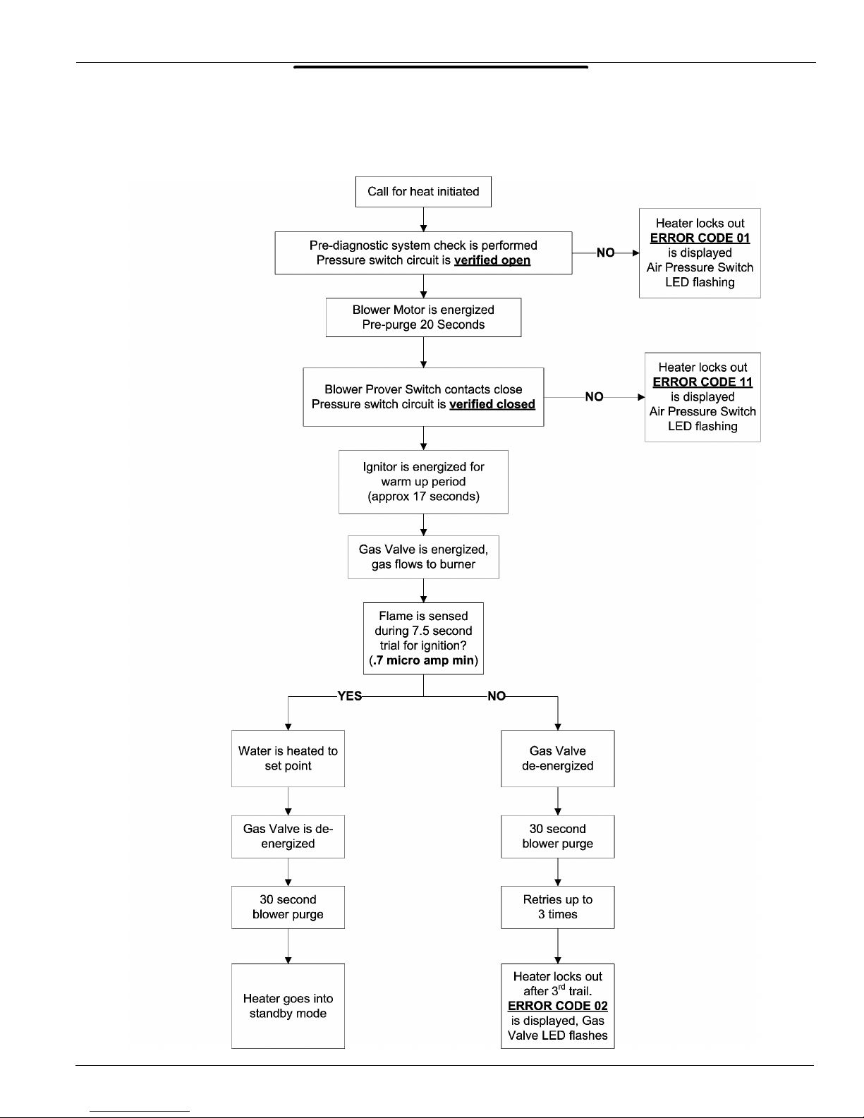
SEQUENCE OF OPERATION
State Water Heaters Technical Training Department
Ashland City, Tennessee © 2004
15 STC-077
Page 17
SUF SERVICE HANDBOOK
OPERATION
CONTROLS
NORMAL INDICATIONS / READINGS / SETTINGS
During Call for Heat
• On/Off switch in the “on” position
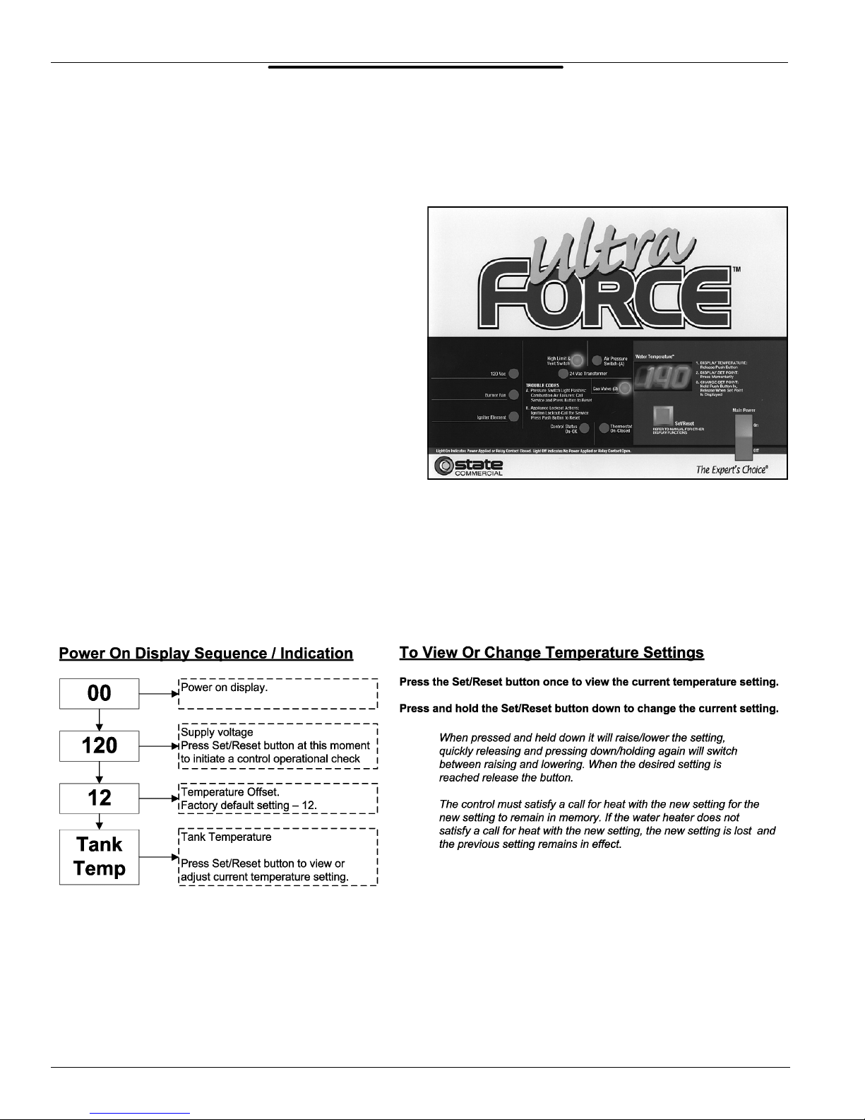
DISPLAY PANEL (CONTROL PANEL)
• Water Temperature F° — current average
tank water temperature displayed
• 120 VAC LED light on
• 24 VAC LED light on
• High Limit/Vent Switch LED light on
• Blower (while blower is running) LED light
on
• Air Pressure Switch (while blower is
running) LED light on
• Control Status LED light on
• Gas Valve (during ignition period and
heating cycle) LED light on
The water temperature inside the tank must be below the current temperature setting to activate a
call for heat. Pressing the Set/Reset button approximately 4 – 6 seconds after powering up the
water heater will reveal the current temperature setting. See the instructions below for how to view
or change temperature settings.
Technical Training Department State Water Heaters
STC-077
16 Ashland City, Tennessee © 2004
Page 18
SUF SERVICE HANDBOOK
OPERATION
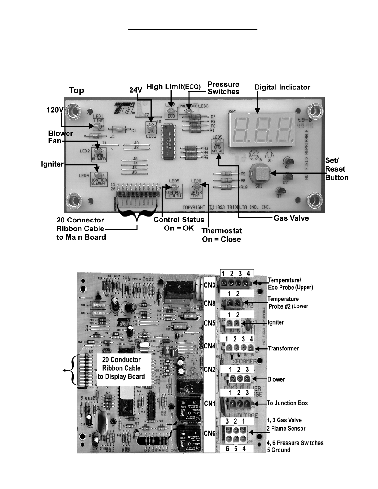
CIRCUT BOARDS
DISPLAY CIRCUIT BOARD
IGNITION CIRCUIT BOARD
State Water Heaters Technical Training Department
Ashland City, Tennessee © 2004
17 STC-077
Page 19

STC-077
SUF SERVICE HANDBOOK
SUF SERVICE HANDBOOK
TROUBLESHOOTING
TROUBLESHOOTING
PRE-SERVICE TIPS
CHECK THAT:
• Insure 120 VAC power supply has correct polarity — check neutral
(white) wire to ground with volt meter. It should read “0” volts.
• Tank is full of water
• Exhaust and intake vent do not exceed allowable limits
• All plugs into boards are secure
• Condensate hose is drained and open
• Proper (natural or propane) gas is supplied
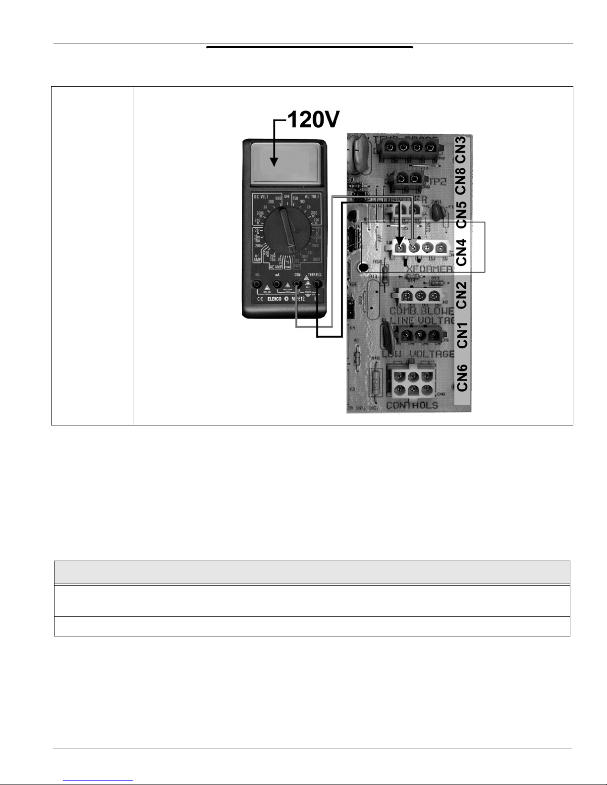
120 VAC TO CONTROL
STEP 1 120 VAC TO CONTROL BOARD
STEP 1: CHECK FOR 120 VAC TO CONTROL BOARD CN1 TERMINAL.
Condition:
• Disconnect plug from CN1 terminal.
• On/Off switch is on.
Check for 120 VAC black wire terminal white wire on plug.
IF… THEN
120 VAC is not present
120 VAC is present reconnect CN1 plug, continue to Step 2.
Technical Training Department State Water Heaters
STC-077
check On/Off switch, turn switch on, replace On/Off switch if defective, restore
power to the water heater.
18 Ashland City, Tennessee © 2004
Page 20
SUF SERVICE HANDBOOK
TROUBLESHOOTING
TRANSFORMER
STEP 2 120 VAC TO TRANSFORMER
STEP 2: CHECK FOR 120 VAC TO TRANSFORMER FROM PIN 1 AND 2 ON CONTROL
BOARD CN4 TERMINAL.
Condition:
• Disconnect CN4 plug from control board.
• On/Off switch is on.
Check for 120 VAC between pin 1 and 2 at CN4 on the control board as illustrated above. Perform
this test with the CN4 plug disconnected and the On/Off switch turned on.
IF… THEN
120 VAC is not present
120 VAC is present reconnect CN4 plug to control board, continue to Step 3.
check CN1 plug connection
replace control board if S tep 1 has been performed and results were successful.
State Water Heaters Technical Training Department
Ashland City, Tennessee © 2004
19 STC-077
Page 21
SUF SERVICE HANDBOOK
TROUBLESHOOTING
TRANSFORMER (CONTINUED)
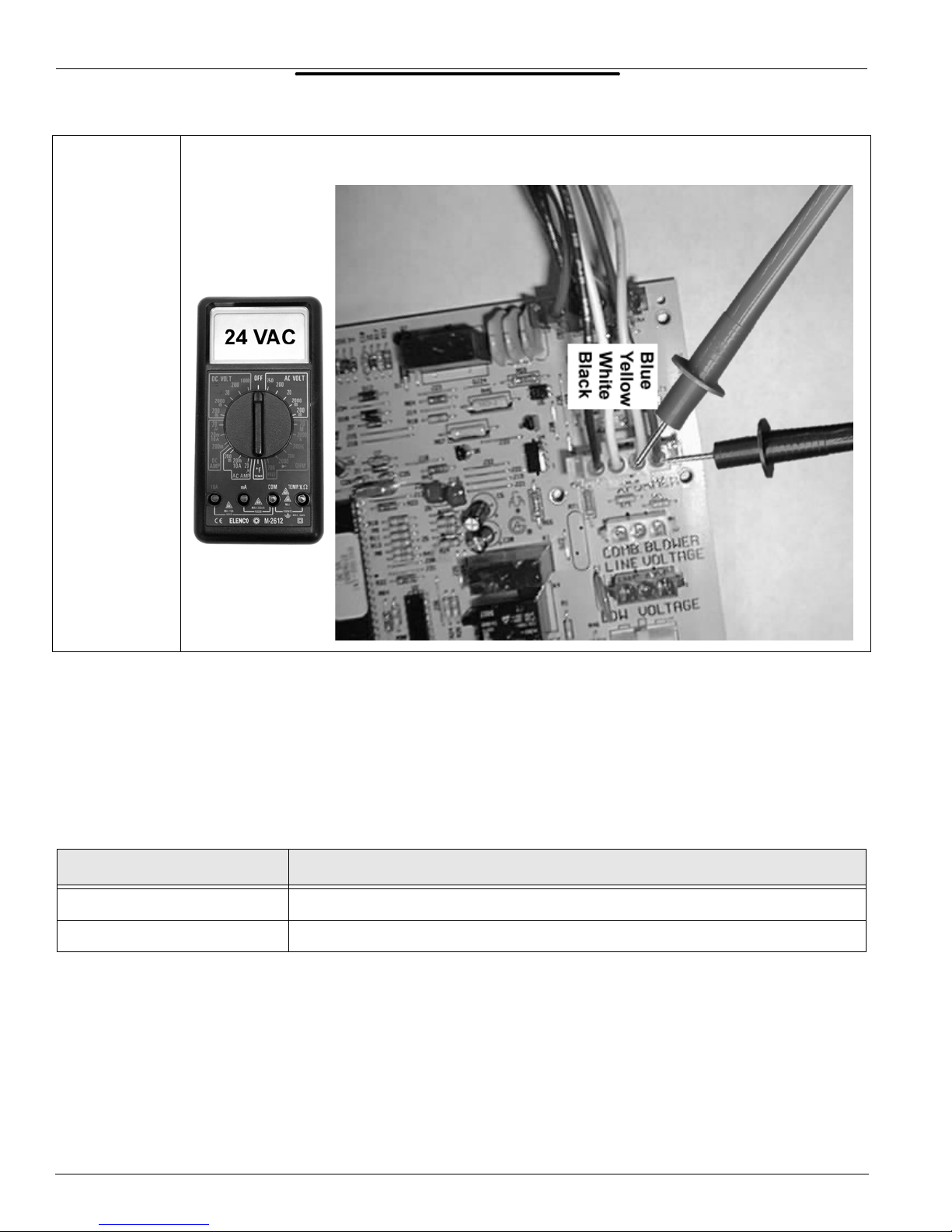
STEP 3 24 VAC FROM TRANSFORMER
STEP 3: CHECK FOR 24 VAC AT TRANSFORMER CN4 PLUG ON CONTROL BOARD.
Condition:
• CN4 is plugged into control board.
• On/Off switch is on.
Insert meter probes into back of CN4 plug on pins 3 and 4 (blue and yellow wires) with CN4
plugged in and power on.
IF… THEN
24 VAC is not present
24 VAC is present continue to Step 4.
replace transformer if S tep s 1 and 2 were performed an d result s were successful.
Technical Training Department State Water Heaters
STC-077
20 Ashland City, Tennessee © 2004
Page 22
SUF SERVICE HANDBOOK
TROUBLESHOOTING
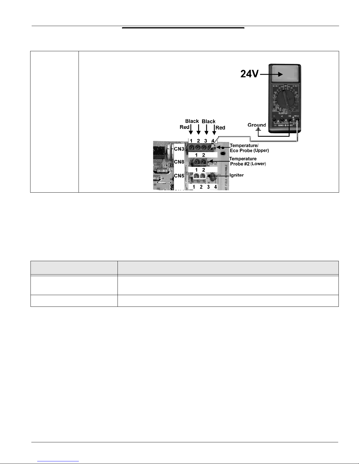
STEP 4 24 VAC TO ECO
ECO CHECK
STEP 4: CHECK FOR 24 VAC BETWEEN PIN 4 ON CONTROL BOARD TERMINAL CN3 AND
GROUND.
Condition:
• Disconnect CN3 plug from control board.
• On/Off switch is on.
Check for 24 VAC between pin 4 of the CN3 terminal on the control board and ground.
IF… THEN
24 VAC is not present
24 VAC is present continue to Step 5.
replace the control board if Steps 1, 2, and 3 have been performed and the results
were successful.
State Water Heaters Technical Training Department
Ashland City, Tennessee © 2004
21 STC-077
Page 23
SUF SERVICE HANDBOOK
TROUBLESHOOTING
ECO CHECK (CONTINUED)
STEP 5 24 VAC FROM ECO
STEP 5: CHECK FOR 24 VAC BETWEEN PIN 1 ON CN3 PLUG AND GROUND.
Condition:
• Reconnect CN3 plug to control board.
• On/Off switch is on.
Insert one meter probe into the back of CN3 plug pin 1, check for 24 V AC between here and ground
with CN3 plugged in and power on. (See illustration above for pin number locations.)
IF… THEN
make sure water temperature in tank is below 160° F, press Set/Reset button on
24 VAC is not present
24 VAC is present continue to Step 6.
Technical Training Department State Water Heaters
STC-077
display panel, replace upper temperature/ECO probe if tank water temperature is
below 160 and Step 4 has been performed and results were successful.
22 Ashland City, Tennessee © 2004
Page 24
SUF SERVICE HANDBOOK
TROUBLESHOOTING
TEMPERATURE PROBE
STEP 6 TEMPERATURE PROBE RESISTANCE
UPPER
TEMPERATURE
PROBE PLUG
LOWER
TEMPERATURE
PROBE PLUG
STEP 6: CHECK RESISTANCE OF THERMISTOR IN UPPER AND LOWER TEMPERATURE
PROBES.
Condition:
• Disconnect CN3 and CN8 plugs from control board.
• On/Off switch is off.
• Multimeter is set to lowest ohms scale above expected resistance.
Check resistance between black wire connects on CN3 and CN8 plugs as shown in illustration
above.
IF… THEN
ohm reading does not approximately correspond to table at given
temperatures
ohm reading does approximately correspond to table at given
temperatures
WATER TEMP
°C °F
3
21
37.5
49
54.5
60
71
82
40
70
100
120
130
140
160
180
OHMS RESISTANCE
26,435
11,974
5,862
3,780
3,066
2,503
1,698
1,177
NOTE: The upper and lower temperature probes contain
thermistors which are heat sensitive resistors. The control
board interprets changes in thermistor resistance as
changes in water temperature.
These thermistors are very reliable and should only be
replaced when:
The resistance test indicates an “open” (infinite resistance)
or a “direct short” (no resistance) circuit.
The nature of the service problem is temperat ur e con tr ol
and the resistance readings are significantly off when compared to the values in the table here at the given temperature.
replace temperature probe if thermistor is open.
shorted, or resistance value is off significantly.
continue to Step 7.
State Water Heaters Technical Training Department
Ashland City, Tennessee © 2004
23 STC-077
Page 25
SUF SERVICE HANDBOOK
TROUBLESHOOTING
PRESSURE SWITCH CONTINUITY
STEP 7 PRESSURE SWITCH CONTINUITY TEST
STEP 7: CHECK FOR CONTINUITY BETWEEN PRESSURE SWITCH TERMINALS WITH
WIRES REMOVED.
Condition:
• On/Off switch is off.
• All wires are disconnected from all pressure switches.
• Multimeter is set to lowest ohms scale.
IF… THEN
blocked inlet switch does not show continuity replace switch.
blocked inlet switch does show continuity continue.
blower proving switch does show continuity replace switch.
blower proving switch does not show continuity continue.
check for minimum supply gas
pressure of
low gas pressure switch does not show continuity
5.0” W.C. natural gas
9.0” W.C. LP gas
replace switch if gas pressures
are above these minimums.
low gas pressure switch does show continuity continue.
blocked outlet pressure switch does not show continuity replace switch.
blocked outlet pressure switch does show continuity
Technical Training Department State Water Heaters
STC-077
reconnect all wires to pressure
switches; continue to Step 8.
24 Ashland City, Tennessee © 2004
Page 26

SUF SERVICE HANDBOOK
TROUBLESHOOTING
BLOWER
STEP 8
120 VAC TO BLOWER
STEP 8: CHECK FOR 120 VAC TO BLOWER FROM CN2 PLUG PIN 1 AND 2.
Condition:
• Reconnect all plugs to control board.
• On/Off switch is on.
• Call for heat is activated.
Insert meter probes into back of CN2 plug on pins 1 and 2 with CN2 plugged in, power on, and a
call for heat activated.
IF… AND THEN
120 VAC is not
present
State Water Heaters Technical Training Department
Ashland City, Tennessee © 2004
replace the control board if call for heat is active and Step 7 has been
performed and results were successful — continue to Step 9A.
25 STC-077
Page 27

SUF SERVICE HANDBOOK
TROUBLESHOOTING
PRESSURE SWITCH PERFORMANCE
STEP 9A TAKE AIR AND GAS PRESSURE READINGS.
Blower prover and blocked outlet pressure
Blower inlet pressure
STEP 9A: CHECK PRESSURE AT SENSING PORTS ON BURNER, BLOWER INLET AND GAS
VALVE.
Condition:
• All wires are reconnected to all pressure switches.
• On/Off switch is on.
• Call for heat is activated.
• Blower is running during trial for ignition.
Remove the air pressure sensing tubes from the sensing ports on the blower inlet and the burner.
Using a digital manometer take a pressure reading with the blower running during a call for heat at
both of these sensing ports. Take a supply gas pressure reading on the inlet side of the gas valve
as outlined in Step 13.
Record all 3 pressure readings and have them on hand. Continue to Step 9B.
AMBIENT ROOM AIR PRESSURE
NOTE: One side of the internal diaphragms on these pressure switches are vented to the
room atmosphere. Due to this construction a negative or positive room air pressure can cause
erratic switch operation and the water heater to shut down. If you suspect a pressure imbalance
between the equipment room and the outdoor atmosphere, “zero” or calibrate your digital
manometer to the equipment room ambient air pressure. With the manometer still on and
calibrated to the equipment room air pressure take the manometer outdoors. If the pressure
reading changes significantly you may have a pressure imbalance between the equipment room
and the outdoor atmosphere. This pressure imbalance may need to be corrected before the water
heater will operate properly.
Insure the combustion/make-up air openings into the equipment room are properly sized. Check for
leaks in ductwork on any nearby air handling equipment. If there is a kitchen vent hood installed in
the building, insure it is properly balanced. Missing or worn fan belts on make up air fans to vent
hoods can cause negative air pressure throughout the building.
Direct vent installations DO NOT eliminate this potential problem.
Technical Training Department State Water Heaters
STC-077
26 Ashland City, Tennessee © 2004
Page 28

SUF SERVICE HANDBOOK
TROUBLESHOOTING
PRESSURE SWITCH PERFORMANCE (CONTINUED)
STEP 9B PRESSURE SWITCH CONTINUITY TEST — OPERATIONAL
SUF 240
ONLY
Air pressure switches
Low gas pressure switch
STEP 9B: CHECK FOR CONTINUITY BETWEEN PRESSURE SWITCH TERMINALS WITH
WIRES REMOVED AND BLOWER RUNNING.
Condition:
• All wires are disconnected from all pressure switches — ends are taped off.
• On/Off switch is on.
• Call for heat is activated.
• Blower is running during trial for ignition.
• Multimeter is set to lowest ohms scale.
The wires disconnected are energized with 24 VAC from the control board. Do not allow these
wires to touch ground — use electrical tape to insulate wire connects during this test.
Check for continuity with an ohm meter between terminals on all pressure switches with the wires
removed and the blower running during a trial for ignition. Restart the water heater as needed.
The pressure switches are wired together in a “series” circuit. For the water heater to continue to
fire and satisfy a call for heat the control board must sense a closed pressure switch circuit.
IF… THEN
continuity is not present between terminals on
one or more pressure switches — the switch
contacts are open.
compare the pressure reading recorded in Step
9A to the value given for that switch in the table
on page 34.
compare to value for correct Model and Series
number in table.
continuity is present.
State Water Heaters Technical Training Department
Ashland City, Tennessee © 2004
if the pressure recorded in Step 9A is within
the table for the switch contacts to remain closed — replace the
pressure switch.
if the pressure recorded in Step 9A is not within
in the table for the switch contacts to remain closed — check for/
clear any restrictions in the vent and/or air intake piping, check
for an excessive number of elbows or equivalent feet of pipe
used in the vent and/or air intake piping.
check for/restore minimum supply gas pressure — Step13.
continue to Step 10.
the value shown in
the value shown
27 STC-077
Page 29

SUF SERVICE HANDBOOK
TROUBLESHOOTING
120 VAC TO IGNITOR
STEP 10
120 VAC TO IGNITOR
STEP 10: CHECK FOR 120 VAC TO IGNITOR FROM PIN 1 AND 2 ON CONTROL BOARD
TERMINAL CN5.
Condition:
• Disconnect CN5 plug from control board.
• On/Off switch is on.
• Call for heat is activated.
• Perform test during ignitor warm up period.
IF... THEN
120 VAC is not present
120 VAC is present continue to step 11.
replace the control board if Steps 7 through 9B have
been performed and results were successful.
Technical Training Department State Water Heaters
STC-077
28 Ashland City, Tennessee © 2004
Page 30

SUF SERVICE HANDBOOK
TROUBLESHOOTING
IGNITOR RESISTANCE
STEP 11 IGNITOR RESISTANCE CHECK
STEP 11: CHECK RESISTANCE BETWEEN TWO WIRE CONNECTS AT CN5 IGNITOR PLUG
END.
Condition:
• On/Off switch is off.
• Disconnect CN5 ignitor plug from circuit board.
• Multimeter is set to lowest ohms scale above 300 ohms.
IF… THEN
ohms reading taken is not between 50 – 300 ohms
ohms reading taken is between 50 – 300 ohms reconnect CN5 plug, continue to Step 12.
replace the ignitor.
State Water Heaters Technical Training Department
Ashland City, Tennessee © 2004
29 STC-077
Page 31

SUF SERVICE HANDBOOK
TROUBLESHOOTING
GAS VALVE TEST
STEP 12
24 VAC TO GAS VALVE
SUF 240 ONLY
STEP 12: CHECK FOR 24 VAC TO GAS VALVE DURING TRIAL FOR IGNITION.
Condition:
• All wires are reconnected.
• On/Off switch is on.
• Call for heat is activated.
• Perform test at end of ignitor warm up period.
Touch meter probes to wiring terminals on gas valve with wires from control board still connected
during the ignitor warm up period.
IF… AND THEN
24 VAC is not present to gas valve
24 VAC is present gas does not flow to burner check for/restore supply gas;
replace control board if Step 9A and 9B have
been performed and results were successful.
check for/clear any restriction in the gas train;
replace the gas valve if the valve will not open
with 24 VAC applied.
24 VAC is pres en t
Technical Training Department State Water Heaters
STC-077
gas does flow to burner continue to Step 13.
30 Ashland City, Tennessee © 2004
Page 32
SUF SERVICE HANDBOOK
TROUBLESHOOTING
GAS PRESSURE CHECK
STEP 13 SUPPLY GAS PRESSURE TEST
SUF 150, 199
Propane
SUF 240 Natural
SUF 150, 199
Natural
Gas Valve
Gas Valve
STEP 13: CHECK AND ADJUST SUPPLY GAS PRESSURE.
Attach manometer or gas pressure gauge to pressure tap on gas valve or use adapter to check
pressure ahead of valve as near as possible to valve. All appliances being served by this gas supply line should be operating.
IF... THEN
supply gas pressure is not between 5.0 and 14” W.C.
natural gas or 11.0 and 14” W.C. propane
adjust supply gas pressure (Recommended supply
minimum is 7.0” W.C. for natural gas models)
proper supply gas pressure is present continue to Step 14.
STEP 14 MANIFOLD GAS PRESSURE TEST
STEP 14: CHECK AND ADJUST MANIFOLD GAS PRESSURE.
IF... THEN
manifold gas pressure is not:
natural gas models
3.5” W.C. ± 0.3” – SUF 155 & 199
4.0” W.C. ± 0.3” – SUF 240
propane gas models
10.0” W.C. ± 0.3” – all propane gas models.
manifold gas pressure is within tolerances given above ignition should occur.
adjust manifold gas pressure to values given for model
and fuel type (within 0.3” W.C. tolerance)
if manifold gas pressure cannot be adjusted to
maintain values given (within 0.3” W.C. tolerance)
replace gas valve.
State Water Heaters Technical Training Department
Ashland City, Tennessee © 2004
31 STC-077
Page 33
SUF SERVICE HANDBOOK
COMPONENT INFORMATION
COMPONENT INFORMATION
FLAME SENSING ROD
PART NUMBER FLAME SENSING CURRENT COMMENTS
192478 0.7 Micro Amp (µ) SUF 150, 199, & 240
HOT SURFACE IGNITOR (HSI)
PART NUMBER VOLTAGE AMP OHMS COLD COMMENTS
192638 120 VAC 1.0 50 – 300 SUF 150, 199, & 240
ORIFICE TABLE
ORIFICE TABLE
SUF MODEL
150 192477-1 0.235 192450-1 0.875
199 192477-0 0.304 192450-0 1.031
240 192477-2 0.360 192450-2 1.196
150 Prop 192477-5 0.141” 192450-5* 0.872
199 Prop 192477-4 0.166” 192450-4* 1.150
MAIN BURNER
ORIFICE NO.
MAIN ORIFICE SIZE
INCHES
AIR ORIFICES
PT. NO.
AIR ORIFICE
SIZE — INCHES
* -4 and -5 stamped with “P” for Propane
NOTE: Hex head of main burner orifice is upstream end — gas flows out of tapered end.
Technical Training Department State Water Heaters
STC-077
32 Ashland City, Tennessee © 2004
Page 34

SUF SERVICE HANDBOOK
COMPONENT INFORMATION
PRESSURE SWTCHES
State Water Heaters Technical Training Department
Ashland City, Tennessee © 2004
33 STC-077
Page 35
SUF SERVICE HANDBOOK
COMPONENT INFORMATION
PRESSURE SWITCHES (CONTINUED)
PRESSURE SWITCHES
PART NUMBER / ACTIVATION PRESSURE
†
Model Blocked Inlet
Normally Closed
Opens on a fall
Blower Prover
Normally Open
Closes on a rise
Low Gas Pressure
Normally Open
Closes on a rise
Blocked Outlet
Normally Closed
Opens on a rise
SUF 150 193363-000 / -0.76” 194706-000 / +1.00” N/A 193362-000 / +2.60”
193355-000 / -1.80” 194706-000 / +1.00” N/A 193357-000 / +4.00”
193355-000 / -1.80” 194706-000 / +1.00” N/A 193357-000 / +4.00”
SUF 199 193363-000 / -0.76” 194706-000 / +1.00” N/A 193364-000 / +2.87”
193356-000 / -2.00” 194706-000 / +1.00” N/A 193357-000 / +4.00”
193356-000 / -2.00” 194706-000 / +1.00” N/A 193357-000 / +4.00”
SUF 240 193361-000 / -0.77” 194706-000 / +1.00” 191149-005 / +5.20” 193357-000 / +4.00”
†. Pressure values are given in inches of water column pressure (“W.C.).
Negative pressure values in this table are preceded by a “-” minus sign and indicate pressure below
atmospheric; in a vacuum. Positive pressures are preceded by a “+” plus sign and indicate pressure above
atmospheric.
Technical Training Department State Water Heaters
STC-077
34 Ashland City, Tennessee © 2004
Page 36

SUF SERVICE HANDBOOK
WIRING DIAGRAMS
WIRING DIAGRAMS
State Water Heaters Technical Training Department
Ashland City, Tennessee © 2004
35 STC-077
Page 37

SUF SERVICE HANDBOOK
SERVICE AIDS
SERVICE AIDS
1. This type product is polarity sensitive. Be certain that your electrical supply wire neutral has
no voltage.
2. This unit will produce condensation — quite heavily at times. The outlet drain hose must be
allowed to drain. Exhaust Vent piping must also drain condensate. Code 11 error would imply
that these must be checked.
3. If the unit is located in a cold climate, take steps to ensure that exhaust vapors are not pulled
into the air intake. Terminate both pipes on direct vent installations in the same area, but max-
imize the distance between them.
4. Do not combine vent these units.
5. Pushing the reset button at random times may alter setting of the control. Note the sequence of
operation comments on when to push this button.
6. If you make a setting change, cycle the heater with this new setting to lock it into memory.
7. The first items to check on a service call
a. Correct venting installation
b. Drainage of condensate from hose and exhaust vent pipe
8. SUF models are certified to 6.800 ft. above sea level with the standard orifice — air and gas.
9. The temperature display board indicates average tank water temperature. If one t ank sensor is
“open”, the indicator will display the active sensor temperature. (Because the top tank sensor
also contains the high limit-24V-sensor, disconnecting this from the control board results in an
error code (04).)
10. Temperature and pressure relief valve operation. Weeping usually indicates thermal expansion. Large volume discharge usually indicates excessively hot water operation.
11. SUF models are well within decimal level limits, but if you desire to lower the installation level
approximately 6 decibels a muffler (Part No. 195334) may be installed in the exhaust vent.
Technical Training Department State Water Heaters
STC-077
36 Ashland City, Tennessee © 2004
Page 38
SUF SERVICE HANDBOOK
SERVICE AIDS
SUF MUFFLER
NOTES:
1. Install muffler in vertical position only.
2. Muffler must be a minimum of 8” from top of condensate elbow.
3. The muffler inlet and outlet are 4” PVC. If venting with a 4” PVC, a 4” x 4” PVC coupling (field
supplied) must be cemented to each end of the muffler. If venting with 3” PVC, a 4” x 3” PVC
reducing coupling (field supplied) must be cemented to each end of muffler (see illustration
above.)
4. Cement muffler into a location using ASTM D-2564 grade cement.
5. Secure muffler to suitable structure.
6. Operate heater through 1 heat cycle to ensure there are no exhaust leaks and there is no
obstruction of exhaust flow.
State Water Heaters Technical Training Department
Ashland City, Tennessee © 2004
37 STC-077
Page 39

SUF SERVICE HANDBOOK
QUESTIONS AND ANSWERS
QUESTIONS AND ANSWERS
Q. How much electrical power is required for a SUF water heater?
A. The SUF models draw approximately 5.0 Amps Max.
Q. When should SUF’s be delimed?
A. Many variables affect the lime build up process including:
• Water temperature — the amount of lime accumulation during the same period of time will be
nearly 2 times great if water is stored at 140 degrees F than at 120 degrees F. A 180° setting
may accumulate seven times more lime — in a period of time — than at 140° setting.
• Volume of water — the more gallons flowing through the SUF, the more rapid the
accumulation.
• Hardness — the harder the water the quicker lime build up occurs. 1 to 3.5 grains per gallons
is “soft”, 3.5 to 7 grains per gallon is “moderate”, 7 to 10.5 grains per gallons is “hard” and
10.5+ grains per gallon is “very hard”. (An aspirin is about 5 grains. One grain is equal to 17.1
parts per million.)
A. Deliming should be done when a slight rumbling or popping sound is detected when the main
burner is on. Check for accumulation through the clean-out opening.
Q. What effect will lime build-up have on the SUF water heater?
A. One eighth inch of scale buildup on the heat exchanger may reduce efficiency as much as
22%; a ¼ inch buildup, as much as 38%.
Less efficient heat transfer means more heat exchanger expansion/contraction stress and premature leakage.
Because the heat transfer to the water is made through a (relatively) small diameter, coil type
exchanger tube, expansion and contraction as well as the shape of the exchanger greatly
reduces buildup on the heat transfer surface. The bottom of the tank should be checked for
dislodged accumulation.
Q. Anode rods (4) provide additional protection against corrosion. When should these be
replaced?
A. When large gouges or pits appear in the anodes, replace them.
Q. How often should the anodes be inspected?
A. Approximately every six months.
Technical Training Department State Water Heaters
STC-077
38 Ashland City, Tennessee © 2004
Page 40
SUF SERVICE HANDBOOK
ERROR CODES
ERROR CODES
CODE INDICATION
00 This is normal operation, 00 is displayed each time the heater is powered up.
Indicates the pressure switch circuit was not open during the prediagnostic system
check when the proper state of the Draft Prover Switches are verified. The Blower
Prover Switch is normally open, the circuit should therefore be open during the
01
prediagnostic system check at the beginning of each cycle. Check Blower Proving
Switch for continuity with the blower off, there should be no continuity, check
pressure switch wiring.
02 Indicates the heater failed to light after 3 trials. Check ignitor, gas pressure.
Indicates the ECO is open. Check water temperature in tank, ECO will open at 202°
04
F and can be reset below 160° F.
Indicates a Temperature Probe is open. Check both probes for proper resistance
05
and continuity.
Indicates the Pressure Switch Circuit did not close after blower was energized.
Check normally open Blower Prover Switch operation, check normally closed
11
Blocked Outlet, Inlet, and Low Gas pressure (SUF 240 only) to ensure they remain
closed. Check for blocked vent pipe (s) or if equivalent feet venting limits have been
exceeded.
15
22
25
CODE #S
ABOVE
199
Indicates temperature sensed by probe(s) is out of bounds, reading is less than
30° F. Check resistance of temp probes, check water temperature in tank.
Indicates Ignition Relay failure. Should be off and it is on. Try resetting, turn power
off and on, if code remains, replace board.
Indicates temperature sensed by probe(s) is out of bounds. Reading is more than
220° F. Check resistance of temp probes, check water temperature.
Internal software or hardware errors, electrical line noise can cause erratic
operation and these error codes. Try adding a “line filter” (available from electrical
suppliers) to the 120 VAC power supply. If these errors codes persist or the control
cannot be reset, replace the control board.
All these errors cause a “soft” lockout with the exception of 04 ECO, which is a “hard” lockout. Soft lockouts will reset automatically after 60 minutes or if the reset button is pushed at any time.
The ECO lockout, error code 04 will have to be manually reset by
pushing the rest button after water in the tank has cooled below
160° F.
State Water Heaters Technical Training Department
Ashland City, Tennessee © 2004
39 STC-077
Page 41

SUF SERVICE HANDBOOK
SERVICE CHECKLIST
SERVICE CHECKLIST
This is not intended to be and all-inclusive list of the problem that the Service Agent may encounter. Any item checked “no” on
this list should be thoroughly investigated and corrective action taken, if required.
SERVICE AGENT: INSTALLATION DATE:
MODEL NUMBER: SERVICE DATE:
SERIAL NUMBER: LOCATION ADDRESS:
GAS TYPE — CHECK ONE
I. CHEC K CLEA RAN CE (CI RCLE AN SW ER)
II.
NATURAL
PROPANE
PROPER GAS VALUE VERIFIED
A. Are exterior clearances adequate?
B. Are interior clearances adequate?
Comments:
CHECK MAKEUP AIR REQUIREMENTS
A. Is the quality of make-up air adequate?
Comments:
YES NO
PHONE ( )
-
yes no
yes no
yes no
B. Is the quantity of make-up air adequate?
Comments:
III.
GAS PRESSURE (FILL IN BLANK) — ALL UNITS ON.
A. Supply gas pressure __ inches of W.C. (flowing)
B. Manifold gas pressure (main burner) __ inches of W.C. (flowing)
Comments:
IV. VENTING (CHECK)
A. Acceptable equivalent footage
B. Proper material
C. Proper exterior installation
D. Condensate will drain
Comments:
V. WATER PIPING
Is the system properly sized?
Is the system properly installed?
Are there any water leaks?
Does the installation have a recirculating system?
If so, is it operational?
VI. SAFETY
A. Air
If exhaust is blocked will unit lockout?
If air intake is blocked will unit lockout?
B. Water Temperature
- Is the thermostat adjusted to the lowest acceptable temperature?
- Does the installation have a mixing valve?
- If so, is it operational?
- What is the outlet temperature of the mixing valve?
NOTE: To minimize the risk of scalding, the manufacturer recommends storing water at 120° F.
Is a properly rated temperature and pressure relief valve installed?
Is there a properly installed expansion tank?
Should there be?
C. Electrical
Is the 120 VAC electrical powers supply properly wired? (including polarity)
Are all the SUF control covers in place?
Is the 120 VAC electrical power supply properly fused?
D. Flammables
Are flammable materials located in the area of the water heater? or air intake?
Are flammable vapors located in the area of the water heater? or air intake?
E. Gas
If the gas supply is reduced or turned off will the unit turn off?
Comments:
yes no
yes no
yes no
yes no
yes no
yes no
yes no
yes no
yes no
yes no
yes no
yes no
yes no
yes no
yes no
yes no
yes no
yes no
yes no
yes no
yes no
yes no
yes no
yes no
yes no
[This service checklist may be photo copied to assist with SUF service calls.]
Technical Training Department State Water Heaters
STC-077
40 Ashland City, Tennessee © 2004
Page 42

970 & 973 Series
SUF SERVICE HANDBOOK
PARTS LIST
SUF SERVICE HANDBOOK PARTS LIST
SUF MODELS 100 – 150, 100 – 199 AND 100 – 240
STC-077
State Water Heaters Technical Training Department
Ashland City, Tennessee © 2004
STATE WATER HEATERS
500 LINDHAL PARKWAY, ASHLAND CITY, TN 37015
PHONE: 1-800-821-2017 • FAX 1-800-644-9306
WWW.STATEWATERHEATERS.COM
41 STC-077
Page 43

SUF SERVICE HANDBOOK
PARTS LIST
ULTRA FORCE SUF MODELS REPLACEMENT PARTS
ITEM DESCRIPTION
SUF
100 150
SUF
100 199
SUF
100 240
SUF
100 150-LP
SUF
100 199-LP
1 Anode 43817-53 43817-53 43817-53 43817-53 43817-53
2 *Barb,Hose 181863 181863 181863 181863 181863
3 Blower 193354 193354 193203 193354 193354
4 Board,Display Panel 192622-0 192622-0 192622-0 192622-0 192622-0
5 Burner Assembly 194114-1 194114 194114-2 194114-5 194114-4
6 Clamp, 3 192696 192696 192696 192696 1926964
7 Clamp, Hose 192806 192806 192806 192806 192806
8 Clamp,Hose,Nylon 191794-1 191794-1 191794-1 191794-1 191794-1
9 Condensate Hose 191746-72 191746-72 191746-72 191746-72 191746-72
10 *Direct Vent Kit 193202 193202 193281 193202 193202
11 Elbow, 90 Degree 192473 192473 192473 192473 192473
12 Exhaust Terminal 192815 192815 192815 192815 192815
13 Flame Rod Assembly 192478 192478 192478 192478 192478
14 Flange, Inlet 192641-1 192641-1 192886-1 192886-1 192886-1
15 Gasket, C.O 99038 99038 99038 99038 99038
16 Igniter Assembly 192638 192638 192638 192638 192638
17 *Instruction Manual 195723 195723 195723 195723 195723
18 Intake Terminal 182167 182167 181762 182167 182167
19 Orifice, Gas 192477-1 192477 192477-2 192477-5 192477-4
20 Panel,Front 195721 195721 195721 195721 195721
21 Plate, C.O 99037 99037 99037 99037 99037
22 *Screen, Exhaust 181662 181662 181662 181662 181662
23 Press. Switch, Low Gas - - - - - - - - - - 191149-1 - - - - - - - - - -
24 Tube, Air 192469-10 192469-10 192469-10 192469-10 192469-10
25 Valve, Drain 26273-4 26273-4 26273-4 26273-4 26273-4
26 Valve, Gas 192797 192797 192454 192454-1 192454-1
27 Valve, Relief 192467 192467 192467 192467 192467
28 Gasket, Burner 192331 192331 192331 192331 192331
29 Metal Cage Assy 195731 195731 195731 195731 195731
Shaded parts are recommended stock items for emergency replacement. Consider gas used in your area only.
*Not illustrated.
Technical Training Department State Water Heaters
STC-077
42 Ashland City, Tennessee © 2004
Page 44

SUF SERVICE HANDBOOK
PARTS LIST
ULTRA FORCE SUF CONTROLS PARTS LIST
ITEM DESCRIPTION
SUF
100 150
1 Blocked Inlet Switch 193355 193363 193361 193355 193356
2 Blocked Outlet Proving Switch 193362 193364 193357 193357 193357
3 Blower Proving Switch 193295 193295 193295 193295 193295
6 Cable to Control 192623 192623 192623 192623 192623
7 Control Board 193822 193822 193822 193822 193822
8 Display Board 192622 192622 192622 192622 192622
9 E.C.O./Upper Probe
10 Lower Temperature Probe
196597 196597 196597 196597 196597
196598 196598 196598 196598 196598
12 Switch-On/Off 193243 193243 193243 193243 193243
13 Transformer 192608-1 192608-1 192608-1 192608-1 192608-1
14 Tubing, Connector 192152 192152 192152 192152 192152
15 Tubing, Pressure 192024-3 192024-3 192024-3 192024-3 192024-3
16 Tubing, Pressure 192024-8 192024-8 192024-8 192024-8 192024-8
Shaded parts are recommended stock items for emergency replacement. Consider gas used in your area only.
SUF
100 199
SUF
100 240
SUF
100 150-LP
SUF
100 199-LP
State Water Heaters Technical Training Department
Ashland City, Tennessee © 2004
43 STC-077
Page 45

NOTES:
SUF SERVICE HANDBOOK
PARTS LIST
Technical Training Department State Water Heaters
STC-077
44 Ashland City, Tennessee © 2004
Page 46

� �� � � ��� �� ���� � �� ���� �� ��� ��� �� �������� ����� �� � � � ��� � � ��
�� ��� � � ����� � ������ � �� ����� �� �� ����� ��� ���� � � �� ! �� ! ""�
COMMERCIAL
The Expert’s Choice®
� � � � � ��� � ��� � � � �� �� �� ���� � � ����� ������
� �� �� �� � �� ��� � � �� ��
� � � ����� �� ��� ��� � � �
� � � ��� � �� ���
� � � �� � � �� � � �
� � � �� �� �� � � �� �� � � �� ���� !
��� � �� � � � �
 Loading...