

Page 1
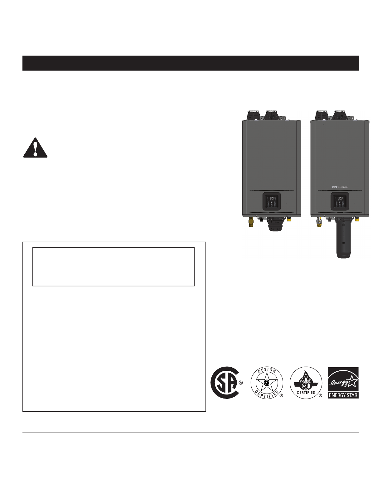
Installa on Instruc ons and
O
Use & Care Guide
ADAPT™ Residen al Gas
Tankless Water Heaters
Residen al On-Demand Gas Tankless Water Heaters
(X3™ TECHNOLOGY available on some models)
Read this manual and the labels on the water heater before you install,
operate, or service it. If you have diffi culty following the direc ons, or
aren’t sure you can safely and properly do any of this work yourself:
• Call our Technical Assistance Hotline which is listed on your warranty. We can
help you with installa on, opera ons, troubleshoo ng, or maintenance. Before
you call, write down the model and serial number from the water heater’s ra ng
plate.
• Incorrect installa on, opera on, or service can damage the water heater, your
house and other property, and present risks including fi re, scalding, electric
shock, and explosion, causing serious injury or death.
WARNING: If the informa on in these instruc ons
is not followed exactly, a fi re or explosion may
result causing property damage, personal injury or
death.
Do not store or use gasoline or other fl ammable vapors
and liquids in the vicinity of this or any other appliance.
WHAT TO DO IF YOU SMELL GAS
• Do not try to light any appliance.
• Do not touch any electrical switch; do not use any
phone in your building.
• Immediately call your gas supplier from a neighbor’s
phone. Follow the gas supplier’s instruc ons.
• If you cannot reach your gas supplier, call the fi re de-
partment.
Installa on and service must be performed by a qualifi ed
installer, service agency or the gas supplier.
MODELS:
THR-160M, THR-180M, THR-199M
THR-160X3, THR-180X3, THR-199X3
LOW LEAD
NTENT
C
Keep this manual with the heater for future reference whenever maintenance, adjustment or service is required.
Retain your original receipt as proof of purchase.
10038042_2000628591
June 2024
Page 2

TABLE OF CONTENT
WATER HEATER BASICS ....................................................................................4
COMPONENT VIEW (X3® Model Shown) ..................................................................................................4
TYPICAL INSTALLATIONS (X3® Model Shown) ............................................................................................5
DIMENSIONS ............................................................................................................................................. 6
SUPPLY CONNECTIONS ..............................................................................................................................7
SPECIFICATIONS .........................................................................................................................................8
IMPORTANT SAFETY INFORMATION .................................................................9
RISKS DURING INSTALLATION AND MAINTENANCE ................................................................................ 10
RISKS DURING OPERATION ......................................................................................................................10
GETTING STARTED .........................................................................................12
Read Before InstallaƟ on ..........................................................................................................................12
Included Items .........................................................................................................................................14
Available Accessories .............................................................................................................................. 15
INSTALLATION................................................................................................ 17
InstallaƟ on Environment ......................................................................................................................... 17
Unit Clearances .......................................................................................................................................17
MounƟ ng the Water Heater ...................................................................................................................17
CombusƟ on Air and VenƟ ng InstallaƟ on .................................................................................................18
VenƟ ng .................................................................................................................................................... 21
Installing the Vent Pipe ...........................................................................................................................23
Exhaust Vent for Indoor InstallaƟ on ........................................................................................................23
Typical VenƟ ng Confi guraƟ ons: ..............................................................................................................24
Clearances for Sidewall TerminaƟ ons .....................................................................................................28
Clearances for RooŌ op TerminaƟ ons ...................................................................................................... 29
Exhaust VenƟ ng for Outdoor InstallaƟ on ................................................................................................32
Outdoor Available Accessories ................................................................................................................32
Gas Supply and Gas Pipe Sizing ............................................................................................................... 33
Gas Conversion InstrucƟ ons ....................................................................................................................35
Water ConnecƟ ons ..................................................................................................................................35
RecirculaƟ on ...........................................................................................................................................36
CombinaƟ on Potable Water and Space HeaƟ ng .....................................................................................38
Dual Purpose Water HeaƟ ng for the State of MassachuseƩ s .................................................................39
2 • Residen al Tankless Gas Water Heater Use and Care Guide
Page 3

TABLE OF CONTENTS
X3® Technology .......................................................................................................................................40
Pressure Relief Valve ...............................................................................................................................40
Condensate Drain ....................................................................................................................................41
Printed Circuit Board BaƩ ery ..................................................................................................................42
Electrical ConnecƟ ons .............................................................................................................................42
Cascade System .......................................................................................................................................43
Accessory ConnecƟ ons ............................................................................................................................ 45
OPERATION ................................................................................................... 46
FOR YOUR SAFETY, READ BEFORE OPERATING ........................................................................................ 46
Start-up InstrucƟ ons ................................................................................................................................46
Shut-Down InstrucƟ ons ...........................................................................................................................46
Emergency Shut-Down ............................................................................................................................46
Temperature Adjustment/Seƫ ng the Temperature ................................................................................49
Unit Conversion Mode .............................................................................................................................50
Confi guraƟ on Mode (A Mode) ................................................................................................................51
Confi guraƟ on Mode (C Mode) ................................................................................................................51
Seƫ ng the Clock .....................................................................................................................................52
Seƫ ng RecirculaƟ on Mode and RecirculaƟ on Type ................................................................................ 53
MAINTENANCE .............................................................................................. 55
Seƫ ng the Pump Timers .........................................................................................................................55
Pump Timer AcƟ vaƟ on ............................................................................................................................56
Regular Maintenance ..............................................................................................................................57
TROUBLESHOOTING .....................................................................................58
Unit Draining & Power Outage
(Freeze ProtecƟ on) ................................................................................................................................. 58
Condensate Drain ....................................................................................................................................58
Inlet Water Filter .....................................................................................................................................58
General TroubleshooƟ ng .........................................................................................................................59
Error Codes ..............................................................................................................................................60
Fault Analysis of Error Codes ...................................................................................................................60
COMPONENT LIST ..........................................................................................67
FLOW RATE .................................................................................................... 73
Residen al Gas Tankless Water Heater Use and Care Guide • 3
Page 4
WATER HEATER BASICS
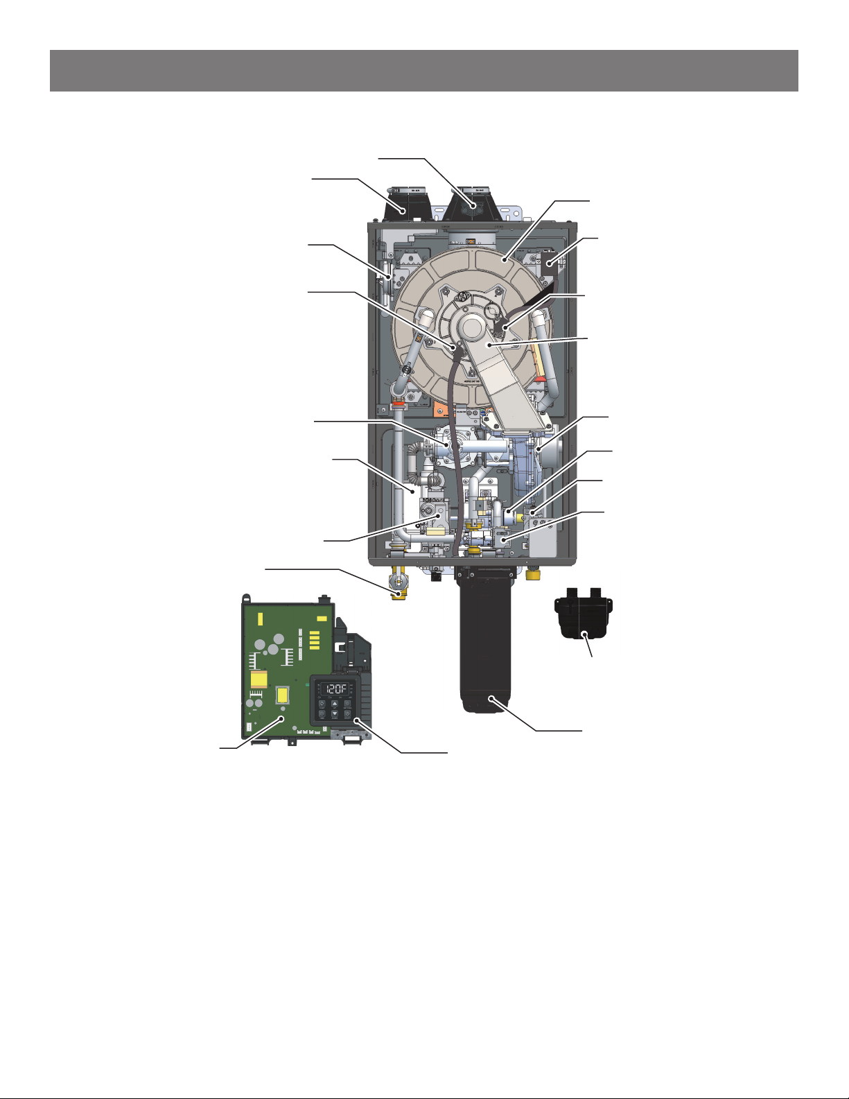
COMPONENT VIEW (X3® Model Shown)
Exhaust Port
Inlet Port
Heat Exchanger
Air Pressure Switch
Flame Sensor
Venturi Assembly
Condensate Trap
Gas Valve
Gas Valve
Pressure Relief Valve
(M Model: Field Supplied)
Igniter
Igniter Rod
Burner Assembly
Fan Motor Assembly
Pump
Flow Sensor Control
Valve Assembly
Bypass Valve
Printed Circuit Board
X3® Technology (X3® Model):
This water heater is equipped with X3® Scale Preven on Technology to inhibit scale forma on within the heat exchanger
tubing of this unit. Part of the X3® Technology’s an -scale protec on comes from the special X3® Cartridge media. The
X3® Cartridge must be installed into the manifold located on the underside of the heater cabinet prior to opera on of
the unit. X3® Scale Preven on Technology reduces the forma on of scale in the heat exchanger, extending the opera ng
life of the unit in typical potable water installa ons. Specifi c water condi ons may impact the effi ciency of X3®, such as
excessive iron or manganese levels. The maximum allowable limit of iron is 0.3 mg/l or 0.3 ppm and manganese is 0.05
mg/l or 0.05 ppm. Levels greater than these will reduce the eff ec veness of the X3. Refer to the guidelines below and
consult a water quality expert to determine if your water is within acceptable X3® and EPA guidelines. NOTE: Pressure
Relief Valve supplied in the box with this model.
Bypass Cartridge (M Model):
The Bypass cartridge will come preinstalled from the factory. Please verify the three screws securing the Bypass
cartridge are ghtened, See Figure 34. NOTE: Pressure Relief Valve will need to be fi eld supplied with this model.
4 • Residen al Gas Tankless Water Heater Use and Care Guide
Bypass Cartridge
(M Model: Alternative Configuration)
X3 Cartridge
Control Display
Page 5
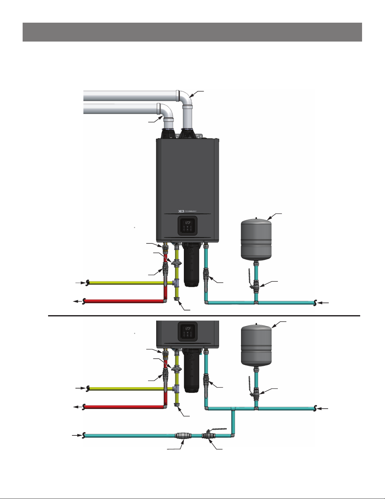
TYPICAL INSTALLATIONS (X3® Model Shown)
Inlet Air
WATER HEATER BASICS
Outlet Venting
NOTE: Condensate Drain not shown for clarity.
Typical Installation
Pressure Relief Valve
(Drain Line not
shown for clarity)
Shutoff Valve
Water Shutoff Valve
Gas Line
HWS
Dedicated Return Line
Pressure Relief Valve
(Drain Line not
shown for clarity)
Shutoff Valve
Water Shutoff Valve
Gas Line
Gas
Gas
Drip Leg
Water
Shutoff
Valve
Water
Shutoff
Valve
Expansion
Ta nk
Water
Shutoff
Valve
CWS
Expansion
Ta nk
Water
Shutoff
Valve
HWS
Return Line
Check Valve
CWS
Drip Leg
NOTE: Condensate Drain not shown for clarity.
Water Shutoff Valve
Residen al Gas Tankless Water Heater Use and Care Guide • 5
Page 6
WATER HEATER BASICS
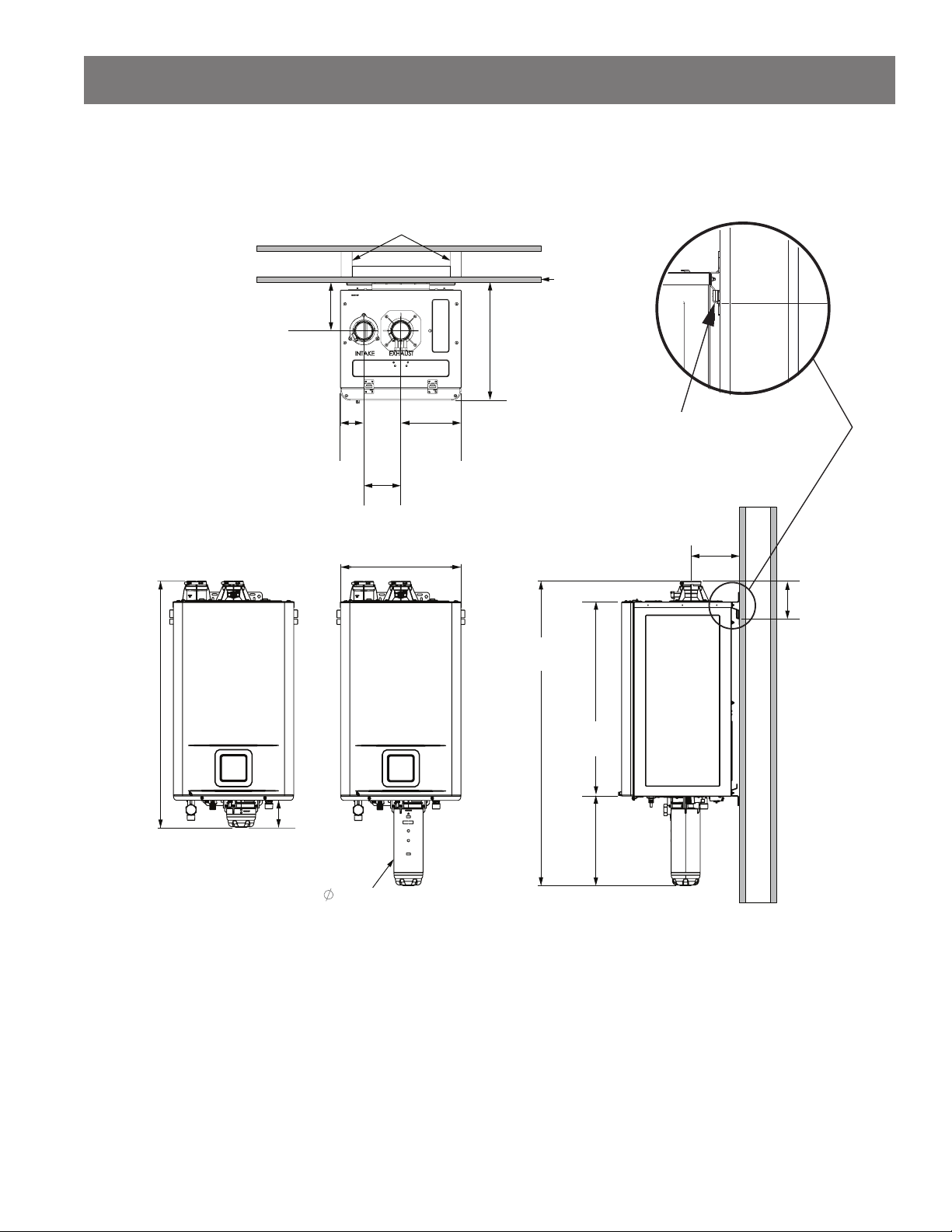
DIMENSIONS
Wall Studs
33.80 in
85.88 cm
6.58 in
16.72 cm
3.22 in
8.22 cm
Dry Wall
5.08 in
12.90 cm
16.54 in
42.00 cm
16.12 in
40.96 cm
8.31in
21.12 cm
106.13 cm
41.78 in
67.82 cm
26.70 in
Water heater wall
mount contact point.
Wall
C
L
6.70 in
17.00 cm
5.09 in
12.92 cm
3.73 in
9.47 cm
4.00 in
10.16 cm
6 • Residen al Gas Tankless Water Heater Use and Care Guide
12.28 in
31.20 cm
Page 7
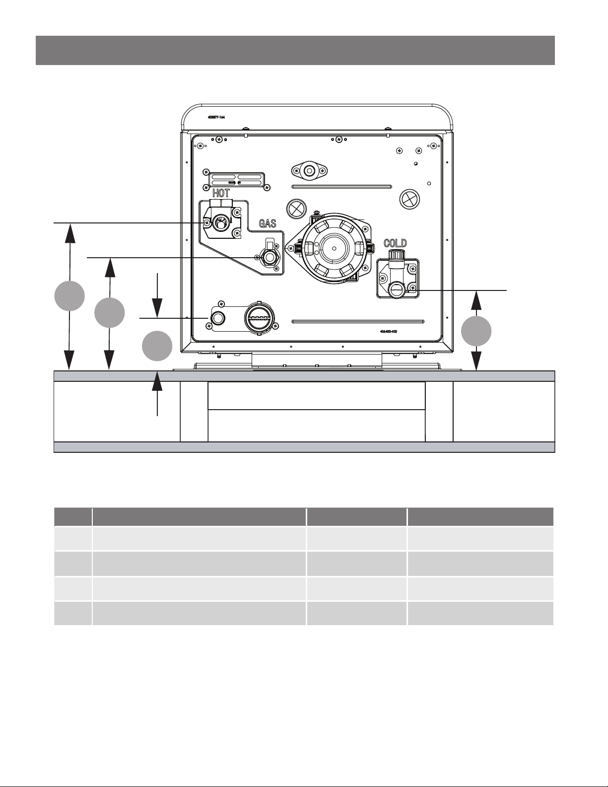
SUPPLY CONNECTIONS
1
2
3
WATER HEATER BASICS
4
WALL
Table 1: Supply Connec ons
Item DESCRIPTION MEASUREMENT CONNECTION SIZE
1 HOT OUTLET 9.00 in/22.86 cm 3/4 in MNPT
2 GAS INLET 6.90 in/17.52 cm 1/2 in MNPT
3 CONDENSATE 3.20 in/8.07 cm 1/2 in MNPT
4 COLD INLET 4.80 in/12.20 cm 3/4 in MNPT
Residen al Gas Tankless Water Heater Use and Care Guide • 7
Page 8
WATER HEATER BASICS
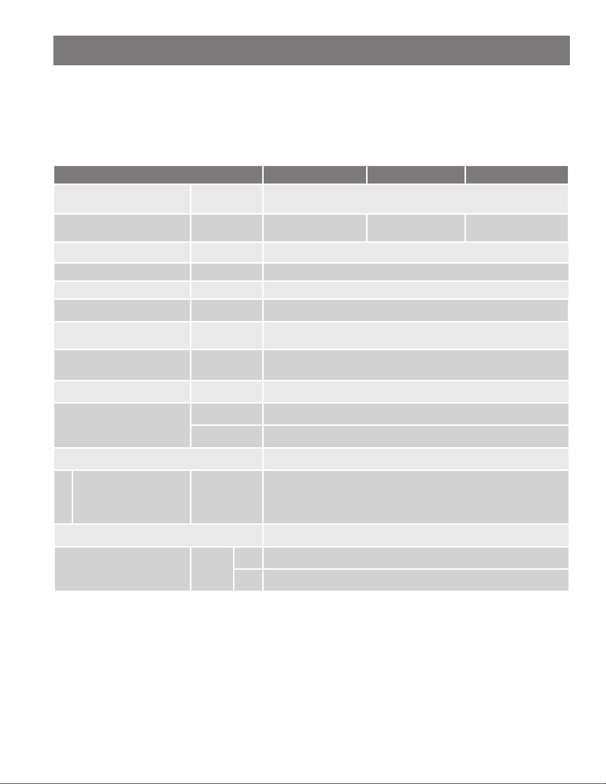
SPECIFICATIONS
X3® Models: Come with the X3® Scale Preven on Technology cartridge and pressure relief valve.
M Models: Come with the Bypass cartridge installed.
All other specifi ca ons are the same.
Table 2: Specifi ca ons
Model THR-160 THR-180 THR-199
Natural Gas/Propane Input
(Minimum Operating Range)
Natural Gas/Propane Input
(Maximum Operating Range)
Gas Connection 1/2 in MNPT
Water Connections 3/4 in NPT
Water Pressure* psi (MPa) 15 - 150 (0.1 - 1)
Water Flow Rate gpm (Lpm) 0.26 - 10.5 (1.0 - 39.7), Activation min: 0.4 (1.5)
Natural gas
Inlet Pressure
Propane
Inlet Pressure
Weight lbs (kg) 104 (47.2)
Dimensions
(including X3®)
Ignition Electronic Ignition
BTU/h 9,000
BTU/h 160,000 180,000 199,000
in W.C. (kPa)
in W.C. (kPa)
inch W 16.54 x H 41.78 x D 16.12
cm W 42.00 x H 106.13 x D 40.96
Min 3.5 (0.87)
Max. 10.5 (2.62)
Min 8.0 (1.99)
Max. 13.0 (3.24)
Supply 120 V, 60 Hz, <5 A
Electric
Water Heater Category** Category IV
Maximum Pipe length
(Hot Water supply line plus the Dedicated
Return line.) See Table 13 for addi onal
informa on.
*40 psi or above is recommended for maximum flow.
**Water Heater Category - Does not apply to Outdoor or Direct Vent Installations.
Category IV - a water heater that operates with a positive vent static pressure and with a vent gas temperature that may cause
excessive condensate production in the vent.
Pipe
Diameter
3/4 in 500 ft (152.4 m)
1/2 in 200 ft (61 m)
NOTE:
• Check the rating plate to ensure that this product matches your specifications.
• The manufacturer reserves the right to discontinue, or change at any time, specifications or designs without
notice and without incurring obligation.
8 • Residen al Gas Tankless Water Heater Use and Care Guide
Page 9
IMPORTANT SAFETY INFORMATION
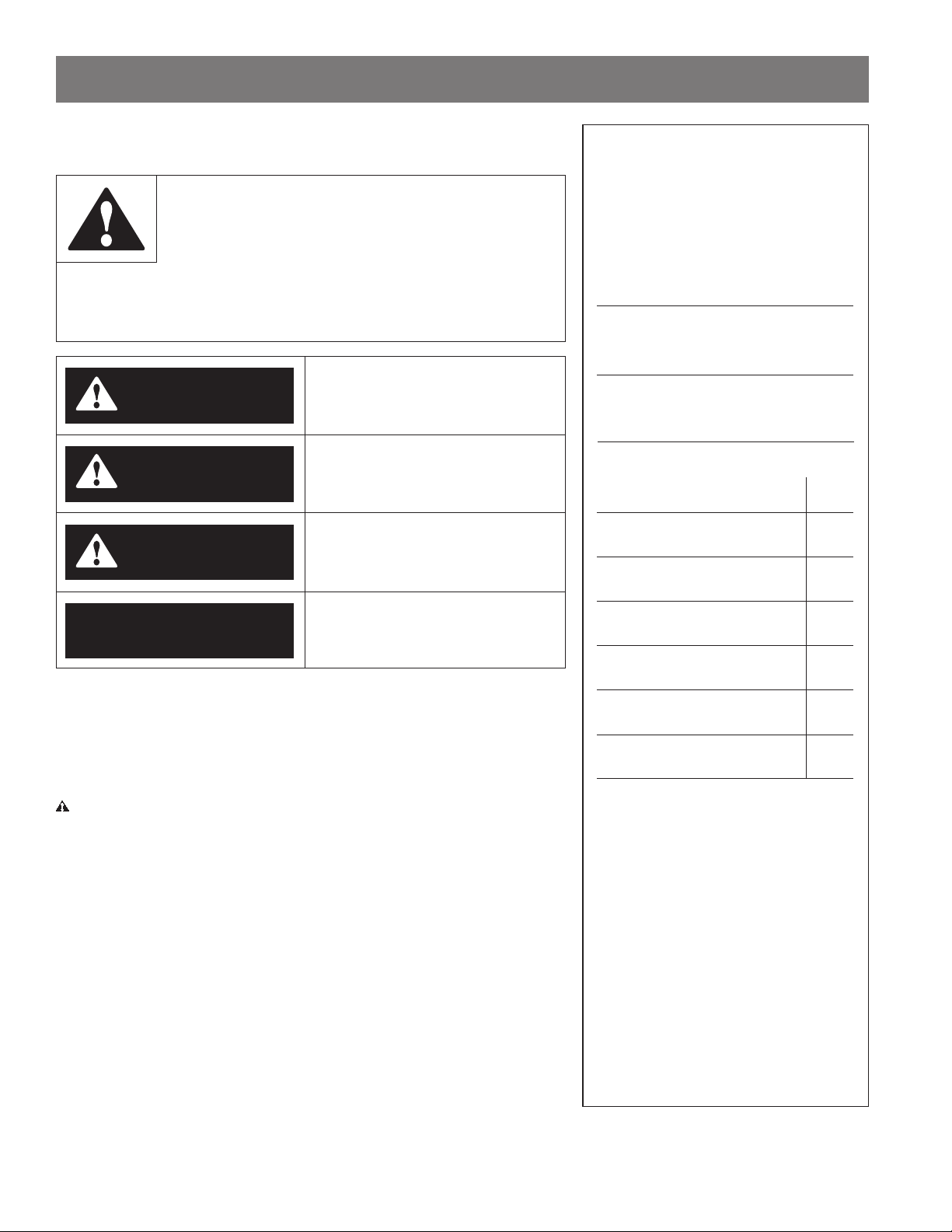
Read and follow all safety messages and instruc ons in this
manual.
This is the safety alert symbol. It is used to alert you to
poten al physical injury hazards. Obey all safety messages
that follow this symbol to avoid possible property damage,
serious injury or death. Do not remove any permanent
instruc ons, labels, or the data plate from either the outside
of the water heater or on the inside of the access panels. Keep this manual
near the water heater.
DANGER indicates a hazardous
DANGER
situa on that, if not avoided, will
result in death or serious injury.
Important informa on to keep
Fill out this sec on and keep this manual
in the pocket of the water heater for
reference.
Date Purchased:
Model Number:
Serial number:
WARNING indicates a hazardous
WARNING
CAUTION
NOTICE
WARNING! If the informa on in these instruc ons is not followed
exactly, a fi re or explosion may result causing property damage, personal
injury or death. Do not store or use gasoline or other fl ammable vapors and
liquids in the vicinity of this or any other appliance.
An odorant is added by the gas supplier to the gas used by this water heater.
This odorant may fade over an extended period of me. Do not depend upon
this odorant as an indica on of leaking gas. We recommend installing a fuel
gas and carbon monoxide detector.
This product is cer fi ed to comply with a maximum weighted average of
0.25% lead content.
situa on that, if not avoided, could
result in death or serious injury.
CAUTION indicates a hazardous
situa on that, if not avoided, could
result in minor or moderate injury.
NOTICE indicates prac ces not
related to physical injury.
Maintenance performed:* Date:
*Operate the Pressure Relief Valve
annually and inspect Pressure Relief
Valve every 2-4 years (see the label
on the Pressure Relief Valve for
maintenance schedule). If no label
is attached to the Pressure Relief
Valve, follow the instructions in the
Maintenance section of this manual.
See the Regular Maintenance section
for more information about maintaining
this water heater.
Residen al Gas Tankless Water Heater Use and Care Guide • 9
Page 10
IMPORTANT SAFETY INFORMATION
To reduce the risk of property
damage, serious injury or death, read
and follow the precau ons below,
all labels on the water heater, and
the safety messages and instruc ons
throughout this manual.
RISKS DURING
INSTALLATION AND
MAINTENANCE
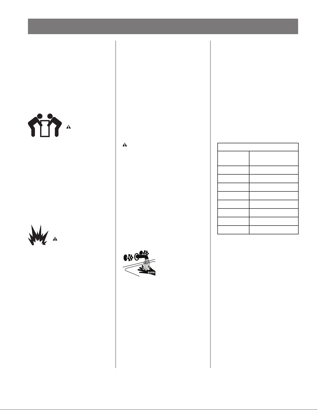
Li ing Risk
WARNING! The
water heater is
heavy. Follow these
precau ons to reduce the risk of
property damage, injuries from li ing
or impact injuries from dropping the
water heater.
• Use at least two people to li the
water heater.
• Be sure you both have a good grip
before li ing.
• Use an appliance dolly or hand truck
to move the water heater.
Explosion Risk
WARNING! Read the
water heater’s data
plate to determine the type of gas
required. Failure to follow these
instruc ons can result in serious
injury or death from explosion, fi re
or carbon monoxide poisoning.
• Do not connect a natural gas water
heater to an L.P. gas supply.
• Do not connect an L.P. gas water
heater to a natural gas supply.
• Use a new gas supply line approved
for Propane or Natural Gas that
meets all local and state/provincial
codes.
• Install a full port shut-off valve on
the gas supply line.
• Maintain the Pressure Relief Valve
properly. Follow the maintenance
instruc ons provided by the
manufacturer of the Pressure Relief
Valve (label a ached to Pressure
Relief Valve). If no label is a ached
to the Pressure Relief Valve, follow
the instruc ons in the Regular
Maintenance sec on of this manual.
An explosion could occur if the
Pressure Relief Valve or discharge
pipe is blocked. Do not cap or
plug the Pressure Relief Valve or
discharge pipe.
Gas Pressure
WARNING! The gas supply
pressure must not exceed the
maximum supply pressure as stated
on the water heater’s ra ng plate.
Have a qualifi ed person (licensed
plumber, gas company personnel,
or authorized service technician)
check for proper gas pressure. Gas
pressures exceeding the maximum
supply pressure as stated on the
water heater’s ra ng plate can
result in serious injury or death from
explosion or fi re.
RISKS DURING
OPERATION
Scalding Risk
This water heater
can make water hot
enough to cause
severe burns instantly, resul ng in
severe injury or death.
• Feel water before bathing or show-
ering.
• To reduce the risk of scalding, install
Thermosta c Mixing Valves (tem-
perature limi ng valves) at each
point-of-use. These valves automa -
cally mix hot and cold water to limit
the temperature at the tap. Mixing
valves are available at your local
plumbing supplier. Follow the manufacturer’s instruc ons for installa-
on and adjustment of the valves.
• Water temperatures over 125°F
(52°C) can cause severe burns
instantly or death from scalding. The
water temperature is set at 120°F
(50°C) from the factory to minimize
any scalding risk. Before bathing or
showering, always check the water
temperature. Higher temperatures
increase the risk of scalding, but even
at 120°F, hot water can scald. If you
choose a higher temperature se ng,
Thermosta c Mixing Valves located
at each point-of-use are par cularly
important to help avoid scalding.
Table 3: Burn/Scald Table
Temperature Time to Produce a
Serious Burn
120°F (49°C) More than 5 minutes
125°F (52°C) 1½ to 2 minutes
130°F (54°C) About 30 seconds
135°F (57°C) About 10 seconds
140°F (60°C) Less than 5 seconds
145°F (63°C) Less than 3 seconds
150°F (66°C) About 1½ seconds
155°F (68°C) About 1 second
For more informa on about changing
the factory temperature se ng, refer
to the “Adjus ng the Temperature”
sec on in this manual.
• Water temperature will be ho er if
someone adjusted the set temperature to a higher se ng.
• Should overhea ng occur or the
burner fail to shut off , turn off the
manual gas supply valve to the
water heater and call a qualifi ed
person.
10 • Residen al Gas Tankless Water Heater Use and Care Guide
Page 11
IMPORTANT SAFETY INFORMATION
To reduce the risk of unusually hot
water reaching the fi xtures in the
house, install Thermosta c Mixing
Valves at each point-of-use.
If anyone in your home is at par cular
risk of scalding (for example, the
elderly, children, or people with
disabili es) or if there is a local code
or state/provincial law requiring a
certain water temperature at the
hot water tap, these precau ons are
par cularly important.
According to a na onal standard
American Society of Sanitary
Engineering (ASSE 1070) and most
local plumbing codes, the water
heater’s thermostat should not be
used as the sole means to regulate
water temperature and avoid scalds.
Water Contamina on Risk
Do not use chemicals that could
contaminate the potable water supply.
Do not use piping that has been
treated with chromates, boiler seal, or
other chemicals. Suitable for potable
water hea ng only.
Fire Risk
To reduce the risk of a
fi re that could result in
property damage, or
serious injury or death:
• Do not store things that can burn
easily such as paper or clothes next
to the water heater.
• Do not store or use gasoline or other
fl ammable substances in the vicinity
of this or any other appliance.
• Do not use this appliance if any part
has been in contact with or been immersed in water. Immediately call a
qualifi ed installer or service agency
to replace a fl ooded water heater.
Do not a empt to repair the unit. It
must be replaced.
Explosion Risk
High pressures in the
water heater can cause
an explosion resul ng in property
damage, serious injury or death. A
Pressure Relief Valve is required to
be installed on the water heater.
A Pressure Relief Valve is supplied
with X3® models and shall be fi eld
supplied for M models. Addi onal
pressure protec ve equipment may
be required by local codes.
A na onally recognized tes ng
laboratory maintains public inspec on
of the valve produc on process
and cer fi es that it meets the
requirements for Relief Valves for Hot
Water Supply Systems, ANSI Z21.22.
The Pressure Relief Valve’s relief
pressure must not exceed the working
pressure ra ng of the water heater as
stated on the ra ng plate.
Carbon Monoxide Risk
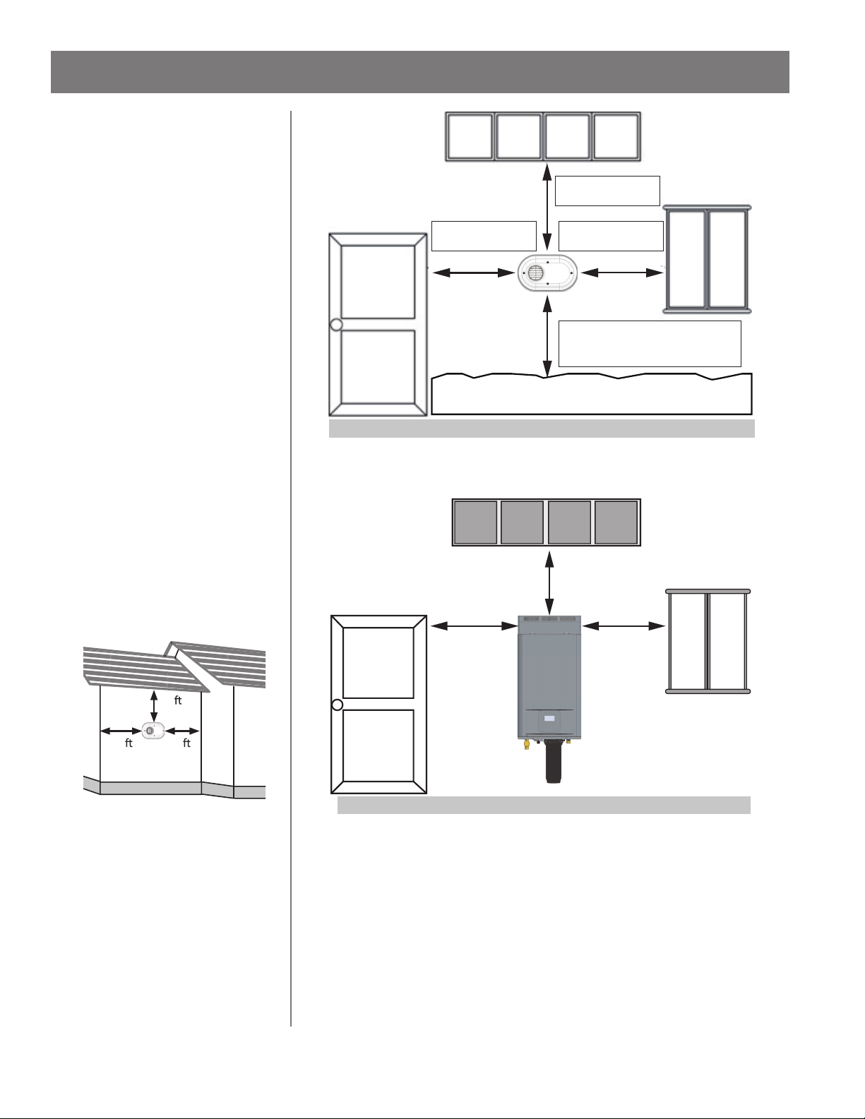
WARNING! This
water heater
operates by burning
gas. Carbon
monoxide is a
colorless, odorless,
gas that is a by-product of burning of
fuels such as coal, wood, charcoal,
oil, kerosene, propane, and natural
gas. Breathing excessive and
abnormal amounts of carbon
monoxide can cause carbon
monoxide poisoning, resul ng in
serious injury or death. This water
heater must be supplied with
adequate combus on air and must
be properly vented to the outdoors.
Have a qualifi ed person (licensed
plumber, authorized gas company
personnel, or authorized service
technician) install the ven ng system
using these installa on instruc ons.
Install a fuel gas and carbon
monoxide detector in the living areas
of your home.
• Failure to follow these instruc ons
can result in serious injury or death
from carbon monoxide poisoning.
Residen al Gas Tankless Water Heater Use and Care Guide • 11
Page 12

GETTING STARTED
Read Before
Installa on
Review all of the instruc ons
1
before you begin work.
Improper installa on can
damage the water heater, your home
and other property, and can present
risks of serious injury or death.
This water heater is designed
2
as a Category IV, posi ve
vented sta c pressure water
heater (vent gas temperatures may
cause excessive condensate
produc on in the vent,) which takes
its combus on air either from the
installa on area or from air ducted to
the unit from the outside. This water
heater must be installed:
• Following all local codes, or in the
absence of local codes, follow the
current edi on of ANSI Z223.1/NFPA
54, Na onal Fuel Gas Code in the
USA or B149.1, Natural gas and propane installa on code in Canada.
• For installa on in manufactured
homes (mobile homes) follow the
current edi on of The Manufactured
Home Construc on and Safety Stan-
dard, Title 24 CFR, Part 3280 and/or
CSA Z240 MH Series, Manufactured
Homes.
• Follow the electrical code require-
ments of the local authority having
jurisdic on. In the absence of such
requirements, follow the current
edi on of the Na onal Electrical
Code ANSI/NFPA 70 in the U.S. or
the current edi on of CSA C22.1
Canadian Electrical Code Part 1 in
Canada.
These are available from the
following:
CSA Group, Inc.
United States:
8501 East Pleasant Valley Road
Cleveland, OH 44131
Canada:
178 Rexdale Blvd.
Toronto, ON
Canada M9W 1R3
Na onal Fire Protec on Associa on
1 Ba erymarch Park
Quincy, MA 02269
Check with local code offi cials about
codes governing this installa on.
Have your installa on inspected by a
code offi cial to ensure the installa on
meets all local codes.
NOTICE: Installa on and service must
be performed by a qualifi ed installer
(for example, a licensed plumber or
gas fi er). Otherwise, the warranty
will be void. The installer (licensed
professional) is responsible for the
correct installa on of the water
heater and for compliance with all
na onal, state/provincial, and local
codes.
Massachuse s code requires this
water heater to be installed in
accordance with Massachuse s
248-CMR 2.00 and 248-CMR 5.00:
State Plumbing Code. Other local and
state/provincial authori es may have
similar requirements or other codes
applicable to the installa on of this
water heater.
Before you start, check the
3
following:
Warning! Do not store or use
fl ammable materials, vapors, or
liquids in the same loca on where
this water heater is installed.
• All gas water heaters require correct
installa on to ensure safe and
effi cient opera on. This manual
must be followed exactly. Read the
en re manual before installa on
and review the Safety Guidelines”
Sec on.
• Carefully plan the installa on loca-
on of the heater and vent termina-
ons.
• The water heater must be installed
where the proper amount of
combus on air will be available to
it at all mes without obstruc ons.
When installed indoors, the water
heater can be direct vented.
• The length of piping between the
water heater and fi xture determines
the me it takes for the hot water
to arrive. Consider installing the
water heater closer to the fi xtures,
if the plumbing system allows for it.
The water heater should be the fi rst
appliance to access the water line
a er u li es water meter.
• Locate your water heater close to a
drain where water leakage will not
do damage to surrounding areas. As
with any water hea ng appliance,
the poten al for leakage at some
me in the life of the product does
exist. A drain pan, or other means of
protec on against water damage, is
recommended to be installed under
the water heater in case of leaks
to lessen the chance of sustaining
property damage. In addi on, you
may install an ac ve water leak
detector with a shutoff valve which
can turn off the water supply in the
event of a leak. The manufacturer is
not responsible for damage due to
water leaks.
• The water heater shall be securely
wall-mounted or mounted on a
stand.
• Maintain proper space for servicing.
Install the unit so that it can be connected or removed easily. Refer to
the "Unit clearances" sec on page
17 for proper clearances.
• For outdoor installa ons, locate the
water heater in an open , unroofed
area. Maintain 3 in. (76 mm) minimum clearance from the le and
right sides of the unit.
• The manufacturer does not recommend installing the water heater
in an a c due to safety issues. See
the installation section for further
information.
12 • Residen al Gas Tankless Water Heater Use and Care Guide
Page 13
• Failure to observe these warnings
could result in severe personal injury,
death, and/or property damage.
GETTING STARTED
Ven ng/Combus on:
• Do not install the heater where water,
debris or fl ammable vapors may get
into the fl ue terminal. This may cause
damage to the heater and void the
warranty.
• Do not locate your heater in a pit or
loca on where gas and water can
accumulate.
• Do not install the exhaust vent for
indoor and outdoor models within
3 (914 mm) of an overhang.
• Do not install the unit where the exhaust vent is poin ng into any open-
ing in a building or where the noise
may disturb your neighbors. Make
sure the vent termina on meets the
required clearance from any doorway
or opening to prevent exhaust from
entering a building. Check local code
requirements prior to installa on.
• Vent termina on must be at least
2 (610 mm) away from both
the inside and outside corners for
outdoor installa on and direct-vent
installa on.
h^ϭŌ;ϯϬĐŵͿŵŝŶ
ĂŶĂĚĂϯŌ;ϵϭĐŵͿŵŝŶ
Figure 2 - Minimum Vent Clearances (Indoor)
h^ϭŌ;ϯϬĐŵͿŵŝŶ
ĂŶĂĚĂϯŌ;ϵϭĐŵͿŵŝŶ
h^ϭŌ;ϯϬĐŵͿŵŝŶ
ĂŶĂĚĂϯŌ;ϵϭĐŵͿŵŝŶ
h^ϭŌ;ϯϬĐŵͿĂďŽǀĞŐƌĂĚĞĂŶĚ
ĂďŽǀĞĂŶƟĐŝƉĂƚĞĚƐŶŽǁůĞǀĞů
ĂŶĂĚĂϭŌ;ϯϬĐŵͿĂďŽǀĞŐƌĂĚĞ
ŶƟĐŝƉĂƚĞĚƐŶŽǁůĞǀĞů
h^ϰŌ;ϭϮϮĐŵͿŵŝŶ
Overhang
Outside
corner
Figure 1 - Sidewall clearances
2
min.
3
min.
2
min.
Inside
corner
• Do not install next to a dryer or any
source of airborne debris that can be
trapped inside the combus on cham-
ber, unless the system is direct-vented. When direct vented, do not install
the air intake near the dryer vent or
any source of airborne debris.
• Do not common vent this water
heater with any other water heaters
or appliances.
h^ϰŌ;ϭϮϮĐŵͿŵŝŶ h^ϰŌ;ϭϮϮĐŵͿŵŝŶ
Figure 3 - Minimum Vent Clearances (Outdoor Ven ng)
Residen al Gas Tankless Water Heater Use and Care Guide • 13
Page 14
GETTING STARTED
Before you start, be sure you
4
have the following tools and
supplies:
• Plumbing tools and supplies appropriate for the type of water pipes in
your home.
• Thread sealant tape or pipe joint
compound approved for potable
water.
• Pipe dope approved for gas
connec ons or gas tape.
• For homes with water lines using
threaded connectors suitable for the
specifi c type of plas c pipe used:
CPVC or PEX (cross-linked polyethylene). Do not use PVC pipe.
• Non-corrosive gas leak detec on
solu on made from hand
dishwashing soap mixed with water
(1 part soap to 15 parts water) or
children’s soap bubbles and a small,
so -bristled brush or approved gas
leak detec on device.
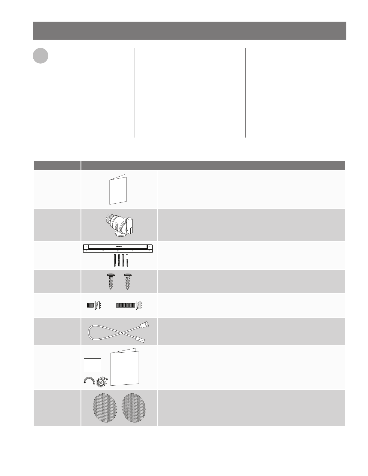
Included Items
Table 4: Items Included with your Water Heater
Item Descrip on
Manual Installa on Instruc ons and Use & Care Guide.
Pressure Relief Valve rated up to 150 psi and the maximum Btu/hr of the
Pressure Relief
Valve
water heater.
(Included with X3® models; Field supplied for M models)
• An appliance dolly or hand truck to
move the water heater.
Recommended Accessories
• Automa c water leak detec on and
shut-off device
• Thermosta c Mixing Valves at each
point-of-use
• Fuel gas and carbon monoxide
detector
Wall Moun ng
Bracket
Screws for
Vent Ports
X3® or Bypass
Cartridge Screws
Cascading Cable
Fuel Conversion
Kit
2 in Bird Screens
(x1)
Kit for moun ng water heater contains:
• Moun ng Bracket (1x)
• 1/4 in x 3 in Lag Bolts (4x)
Screws to secure the vent piping to the vent ports. See “Installing the Vent
Pipe” on page 23.
• 3/16 in x 3/8 in Vent Screw (x2)
Screws to secure the X3® Cartridge
(x2)
• M4-12 mm (1x)
• M4-25 mm (2x)
Cascading Cable for electronically connec ng tankless water heaters in
series for greater output.
• P/N 100377343
Convert heater from Natural Gas (NG) to Liquid Propane (LP). Kit contains:
• LP Diaphragm
• Gas Conversion Label (1x)
• Gas Conversion Instruc on (1x)
• Plas c Retainer (1x)
Bird screen to restrict small animals, birds, pests, and other foreign objects
from entering the vent system. Kit contains 2 screens sized for 2 in vent
elbows.
14 • Residen al Gas Tankless Water Heater Use and Care Guide
Page 15
Available Accessories
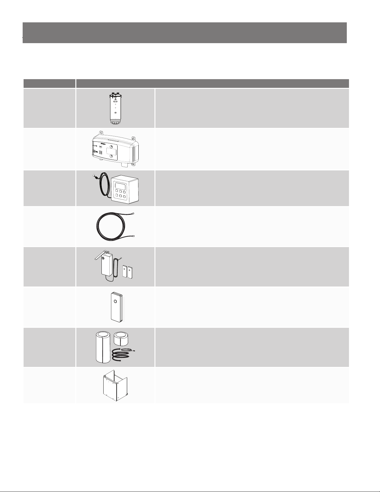
Table 5: Accessories available for your Water Heater
Item Descrip on
X3® Cartridge
Wi-Fi Module Kit
GETTING STARTED
Add to an M model heater to prevent scale buildup and eliminate the need
for annual descaling maintenance.
• P/N 100368986
Wi-Fi Module for electronically connec ng tankless water heaters to the
Internet and adapter to connect to the water heater.
• P/N 100371922
Remote
Temperature
Controller
Communica on
Cables
Remote
Recircula on Kit
Individual Spare
Bu ons
Cartridge Freeze
Protec on
Remote Temperature Controller with 10 (3 m) cable.
• P/N 100377310
Communica on Cable Extensions for Remote Temperature Controller, Wi-Fi
Module, or Remote Recircula on Kit.
• P/N 100377341 for 10 (3 m)
• P/N 100377342 for 32 (10 m)
Remote Recircula on Kit engages heater and recircula on at the touch of
the bu on for on-demand hot water. Kit contains:
• P/N 100371920 for One Receiver and Two Bu on Kit
• P/N 100371921 for One Receiver and Three Bu on Kit (Not Pictured)
Add more Remote Recircula on Bu ons to a system as needed. Add up to
a maximum of 30 bu ons.
• P/N 100377309
Cartridge Freeze Protec on can add an extra layer of freeze protec on to
external cartridge.
• P/N 100325654 for X3® Models
• P/N 100371918 for Bypass Models
Pipe Cover
Pipe Cover protects plumbing connec ons to the heater while improving
the appearance of the installa on. Affi xes to bo om of heater.
• P/N 100374697
Residen al Gas Water Heater Use and Care Guide • 15
Page 16
GETTING STARTED
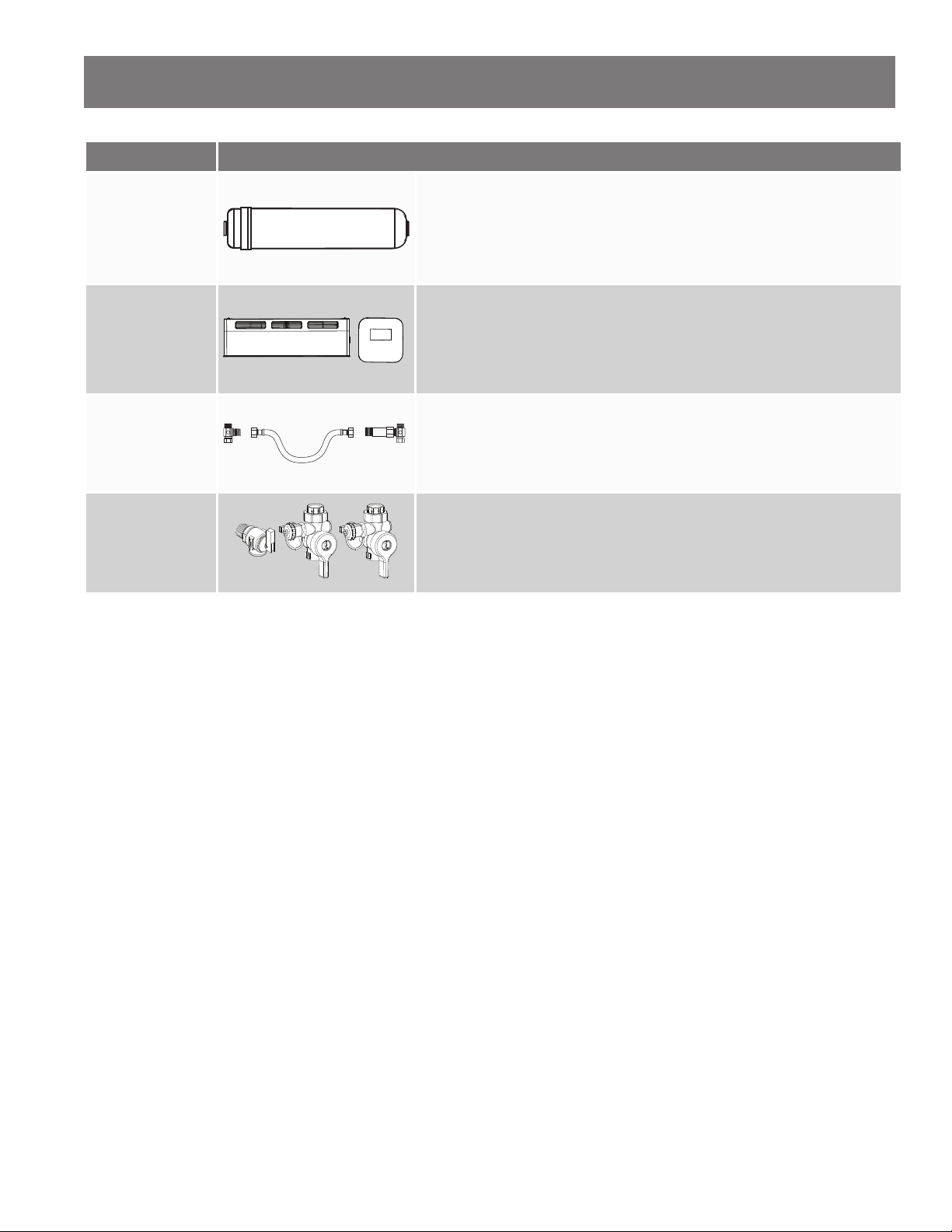
Item Descrip on
Neutralizer Assembly neutralizes the condensate (acidic water) that forms
Neutralizer
Assembly Kit
in the heat exchanger of the water heater. It connects to the condensate
drain port of the water heater by using connectors included with the
neutralizer kit.
• P/N 100112159
Outdoor Vent Cap
Kit
Crossover Valve Kit
Isola on Valve
Kit with Pressure
Relief Valve
Outdoor Installa on Kit containing the outdoor vent cap and User Interface
Cover
• P/N 100369060
Crossover Valve for recircula on systems without a dedicated return line.
The kit includes a lead free Stainless/Brass Crossover Valve, Brass Tees and
2 . Flex Hose.
• P/N 100327167
Isola on Valve supports rou ne maintenance and allows for draining
and fl ushing the heater; whereas, the Pressure Relief Valve, as the name
implies, serves to limit internal pressure in the system.
• P/N 100112156
16 • Residen al Gas Water Heater Use and Care Guide
Page 17
)
INSTALLATION
Installa on Environment
Proper moun ng and clearance
The water heater shall be securely
mounted on a wall that can support
the weight of the water heater. A wall
moun ng bracket is supplied with the
water heater to securely mount the
water heater to wall studs. The water
lines, gas line, condensate drain line,
and pressure relief valve discharge
line shall be supported using fi eld
supplied pipe hangers. The water
heater shall not bear the weight of
these lines. The water heater requires
proper installa on clearance for
opera on and service as described in
Unit Clearances sec on.
Warning! The installer (licensed
professional) is responsible for the
correct installa on of the water
heater and for compliance with all
na onal, state/provincial, and local
codes.
Atmosphere temperature
Install the water heater in a
heated area where below freezing
temperatures cannot occur. A pipe
cover is recommended when the
water heater is installed outdoors
because it provides be er protec on
from the elements. The warranty will
not be covered if the water heater is
damaged due to freezing. See ”Freeze
Protec on System” on page 57.
Combus on air supply
The water heater requires fresh
combus on air and should be
free of corrosive elements and
fl ammable vapors. If it is installed in
a contaminated area or in a confi ned
area, direct ven ng installa on is
recommended.
Proper ven la on
For proper opera on the water heater
must be vented in accordance with
the sec on “Ven ng” of the current
edi on of the ANSI Z223.1/NFPA 54,
Na onal Fuel Gas Code in the United
States and/or Sec on 8 of the B149.1,
Natural gas and propane installa on
code in Canada, as well as applicable
local building codes.
Condensate Drain line
The condensate produced is acidic.
Drain the condensate in accordance
with all local codes and common
safety prac ces.
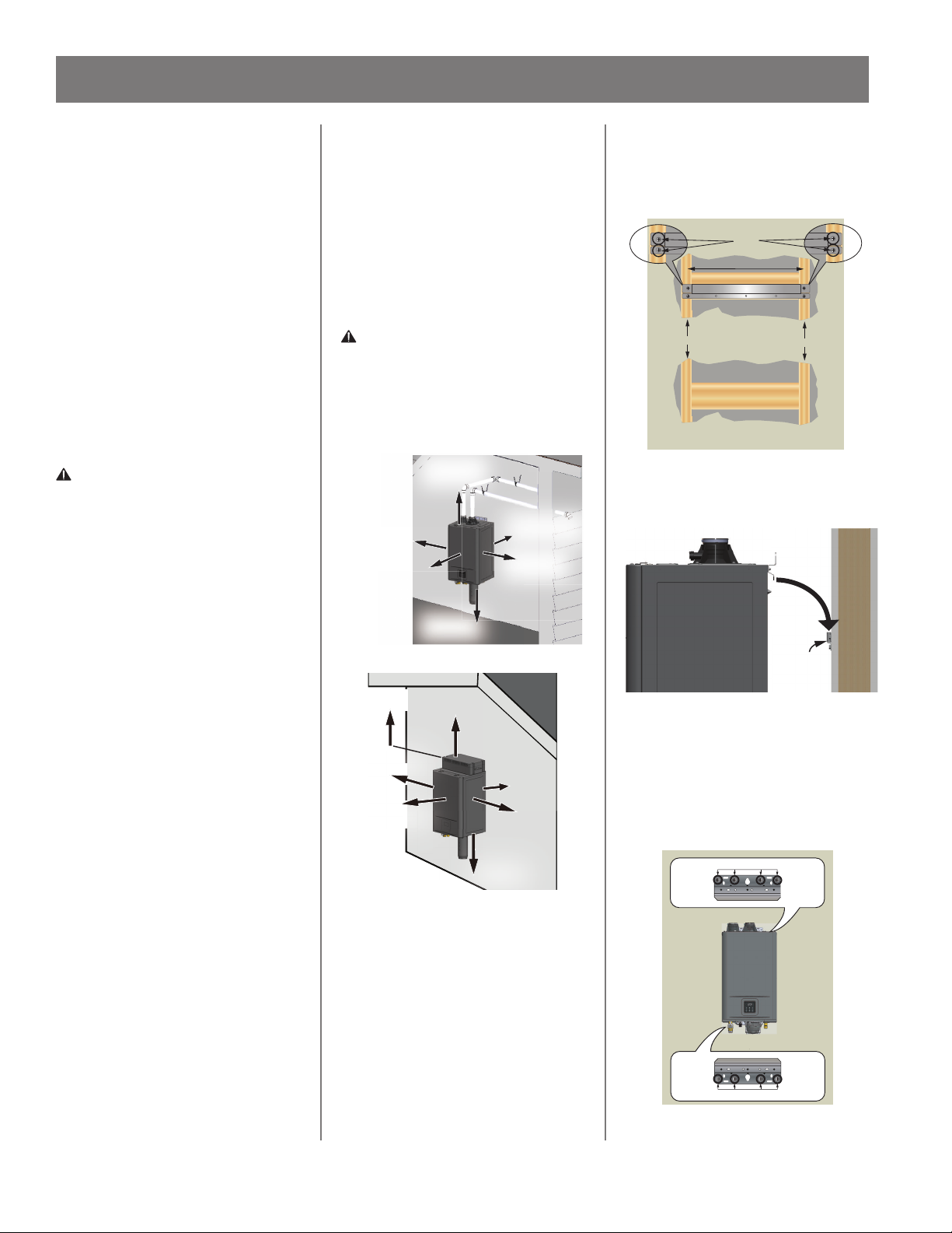
Unit Clearances
Warning! Maintain all clearances
around the water heater. Failure
to do so could create a fi re hazard,
poten ally leading to death, serious
injury, and/or property damage.
Indoor
Top:
12 in (305 mm)
Side:
3 in (76 mm)
Front:
4 in (102 mm)
Bottom:
18 in (458 mm)
Figure 4 - Indoor Clearances
Overhang:
36 in (914 mm)
Side:
3 in (76 mm)
Front:
4 in (102 mm)
Figure 5 - Outdoor Clearances
Top:
12 in (305 mm)
Back:
0.5 in (13 mm
Side:
3 in (76 mm)
Back:
0.5 in (13 mm)
Side:
3 in (76 mm)
Bottom:
18 in (458 mm)
It is recommended that the front
should have 24 inches (610 mm) of
clearance for maintenance.
Moun ng the Water
Heater
1. Secure the wall moun ng bracket
with the four supplied lag bolts to
the wall studs. See Figure 6. DO
NOT secure to the drywall only.
NOTICE: The supplied fasteners
are for wood studs only. When
moun ng on any other surface
use fasteners approved for that
wall material/construc on. Make
sure to level the bracket.
Screws
16” (406.4 mm) Center
Horizontal Blocking - Top
Wall Stud
Horizontal Blocking - Bottom
New Construction Configuration Shown:
Drywall cut away to show horizontal bracing.
Figure 6 - Wall bracket installa on.
Wall Stud
1. Hang the water heater on the wall
bracket. See Figure 7.
Wall
Bracket
Figure 7 - Moun ng the water heater.
2. Secure the water heater fi rmly
fastening appropriate screws
into the upper bracket/bo om
brackets of the water heater and
wall. NOTICE: these screws are
not provided.
Securewithscrews.
Securewithscrews.
Figure 8 - Use moun ng screws.
Residen al Gas Tankless Water Heater Use and Care Guide • 17
Page 18
INSTALLATION
Combus on Air and
Ven ng Installa on
Combus on Air
Before installing the water heater, you
must determine the amount of air
needed to supply this water heater
and any other gas appliances in the
same area and provide adequate air
for combus on and ven la on. This
sec on does not apply if the water
heater is direct vented. Consult a
qualifi ed person if you’re unsure of
the proper way to supply air to your
water heater.
WARNING! This gas water heater
requires an adequate source of
clean air for combus on and
ven la on. Without suffi cient air,
your water heater will have frequent
outages and may emit excessive
and abnormal amounts of carbon
monoxide.
Before beginning:
Calculate total Btu/hr ra ng of all
appliances.
To calculate the combus on air and
ven la on required, add up the
total Btu/hr ra ngs of all gas burning
appliances (e.g., water heaters,
furnaces, clothes dryers) in the same
area.
Your water heater’s Btu/hr ra ng is
on the ra ng plate, located on the
side of the water heater. The Btu/
hr ra ngs should be on the other
appliances’ data plates. If you have
trouble determining the Btu/hr
ra ngs, contact the manufacturer or
have a qualifi ed person determine the
ven la on requirements.
NOTICE: If you are replacing your
old water heater with one that has a
higher Btu/hr ra ng, the amount of
ven la on required may be greater.
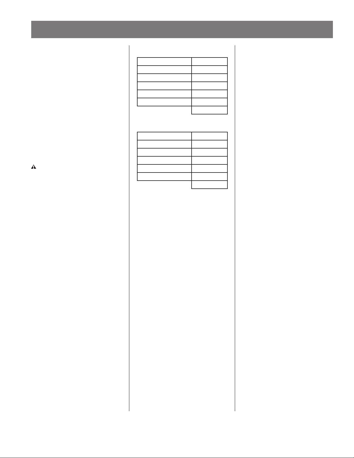
Example:
Gas Burning Appliance Btu/hr Ra ng
Gas Water Heater 199,000
Furnace 75,000
Dryer 20,000
Total 294,000
Your Appliances:
Gas Burning Appliance Btu/hr Ra ng
Gas Water Heater
To ta l
Op on A: Installa on without
outside ven la on (not
recommended)
Ven la on with outdoor air is
recommended for all installa ons.
Even if the water heater is installed in
a large, open room inside the house,
outdoor air is usually needed because
modern homes are very ghtly sealed
and o en do not supply enough air
to the water heater. However, when
installed in a large indoor space, it
may be possible to provide enough air
without outside ven la on. If you are
unsure if your installa on loca on has
enough ven la on, contact your local
gas u lity company or code offi cials
for a safety inspec on.
The following instruc ons will help
determine if it may be possible to
install without outside ven la on. If
there is not enough ven la on, you
will need to ven late with outside air.
Check for Chemicals:
Installa ons where corrosive
chemicals may be present require
outside air. Air for combus on and
ven la on must be clean and free of
corrosive or acid-forming chemicals
such as sulfur, fl uorine, and chlorine.
Ven la on with outside air will reduce
these chemicals, but it may not
completely eliminate them. Failure
due to corrosive chemicals is not
covered by the warranty. Examples of
loca ons that require outside air due
to chemicals include:
• Beauty salons
• Photo processing labs
• Indoor pools
• Laundry, hobby, or cra rooms
• Chemical storage areas
Products such as aerosol sprays,
detergents, bleaches, cleaning
solvents, gasoline, air fresheners,
paint and varnish removers, and
refrigerants should not be stored or
used near the water heater.
A1: Calculate the air volume of
the room
Air requirements depend on the size
of the room.
Floor Area (square feet) x Ceiling
Height (feet) = Room Volume (cubic
feet)
If there are large objects in the
room (e.g., refrigerator, furnace,
car), subtract their volume from the
volume of the room to get a be er
es mate of the air available.
Room Volume – Object Volume = Air
Volume
A2: Calculate required air
volume
A water heater installed in an
unconfi ned space, such as an a c or
garage, requires that the space be at
least 50 cubic feet per 1,000 Btu/hr
of the total input for all gas burning
appliances in the same area.
[Total Btu/hr/1000] x 50 = Cubic feet
of air required.
18 • Residen al Gas Tankless Water Heater Use and Care Guide
Page 19

INSTALLATION
Example:
(294,000 / 1000) x 50 = 14,700
If the air volume of the room is less
than the required air volume, you
must provide two permanent outside
air openings that draw in suffi cient air.
Use Op on B.
If the air volume of the room is
greater than the required air volume,
it may be possible to install the water
heater without outside ven la on.
A3: Check that combus on
ven la on is adequate
Because modern homes are o en
well-sealed to prevent dra s, a
large room may not provide enough
combus on air without ven la on.
Confi rm that your installa on has
enough combus on air.
Op on B: Installa on with
outside ven la on
Ven la on with outside air is
recommended, and, for most
installa ons, is needed. There may be
exis ng ven la on that is adequate,
or you may need to add more
ven la on.
Supplying outside air typically requires
two openings. One opening must be
within 12 inches from the fl oor and
the second opening must be within
12 inches from the ceiling. Although
a single opening is not preferred, you
may use a single opening to outside
air if the minimum free area is sized
according to Table 6. Two openings
must be used when ven la ng with
air from another room.
B1: Determine type of
ven la on
There are several types of ven la on
that can be used:
1. Direct to outdoors
2. Ver cal ducts
3. Horizontal ducts
4. Single opening (not recommended); must be at least 100
square inches. Not appropriate
for confi ned spaces smaller than
50 cubic feet per 1,000 Btu/hr as
calculated in sec on A or when
ge ng air from another room.
5. From a larger room inside the
house (not recommended —
refer to sec on A to determine
if the combined volume of the
room may be adequate)
B2: Determine minimum free
area required for each vent
opening
The size of the vent openings depends
on the total Btu/hr ra ng of all
appliances in the space (use your
calcula on from “Before Beginning”)
and the type of vent used. Table 6
provides the minimum free area for
each vent opening depending on the
type of ven la on.
B3: Calculate minimum size of
vent openings and ducts
The vent cross-sec onal area needed
to provide the free area depends on
the covering on the vent openings.
Typical vents use louvers or grilles to
protect the opening. The louver or
grille itself blocks some of the free
area, so the opening may need to be
larger to meet the minimum free area
requirements.
Use the following formula to calculate
the required cross-sec onal area:
Cross-sec onal area = minimum free
area required ÷ percent free area of
covering (in decimals – e.g., 60% = .6)
For example, an installa on area that
requires openings with 100 square
inches of free area would need 134
square inch openings if using metal
louvers rated at 75% free area
(100 sq in ÷ .75 = 134 sq in).
If you do not know the % (percentage)
free area for your louver or grille, use
the following values:
• For wood louvers or grilles: 20%
• For metal louvers or grilles: 60%
Follow these rules to ensure that
vents and ducts provide adequate air
fl ow:
• Each vent opening must be no smaller than 100 square inches.
• Ducts must have the same cross-sec onal area as free area of the
opening.
• Rectangular ducts must have a
minimum dimension of no less than
three inches.
• All screens must have mesh ¼ in or
larger.
• Movable louvers must be locked
open or interconnected with the
equipment so that they open automa cally during opera on.
• Keep louvers and grilles clean and
free of debris or other obstruc ons.
B4: Check that air source is
clean and free of chemicals
Air for combus on and ven la on
must be clean and free of corrosive
or fl ammable chemicals. A failure due
to corrosive chemicals in the air is not
covered by the warranty. Combus on
air must be free of acid-forming
chemicals such as sulfur, fl uorine, and
chlorine. Be sure that air at the vent
inlets is free of such chemicals.
B5: Check that combus on
ven la on is adequate
To confi rm that your installa on has
enough combus on air.
Residen al Gas Tankless Water Heater Use and Care Guide • 19
Page 20
INSTALLATION
p
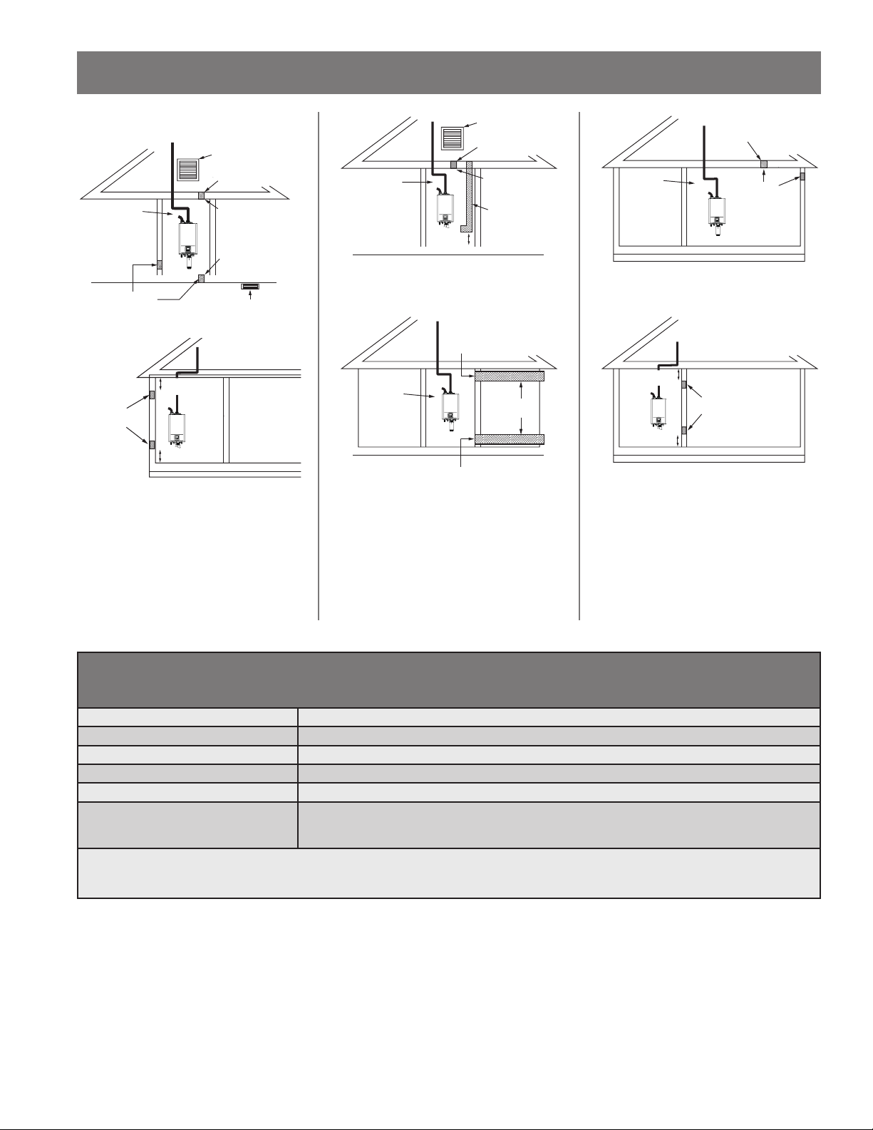
Combus on Air Supply Op ons
Gable vent
to outdoors
Install above
ŝŶƐƵůĂƟŽŶ
ŽŶĮŶĞĚ
Space
Outlet air to
2
;ϲϱĐŵ2)
ĂƫĐϭŝŶ
per 4,000 Btu/hr
/ŶůĞƚĂŝƌĨƌŽŵ
ƚŚĞĐƌĂǁůƐƉĂĐĞ
KƉĞŶĨŽƵŶĚĂƟŽŶǀĞŶƚ
ŽŶĮŶĞĚ
^ƉĂĐĞ
Alternate
Air Inlet
2
ϭŝŶ
;ϲϱĐŵ2)
er 4,000 Btu/hr
Figure 9 - Direct to Outdoors Openings
12 in (305 mm)
maximum
Two permanent
Openings
1 in2 (6.5 cm2)
per 4,000 Btu/hr
12 in (305 mm)
maximum
Figure 10 - Direct to outdoors openings. Two
permanent openings.
'ĂďůĞǀĞŶƚ
ƚŽŽƵƚĚŽŽƌƐ
/ŶƐƚĂůůĂďŽǀĞ
ŝŶƐƵůĂƟŽŶ
ŽŶĮŶĞĚ
^ƉĂĐĞ
ϭϮŝŶ;ϯϬϱŵŵͿ
ŵĂdžŝŵƵŵ
Outlet air to
ĂƫĐϭŝŶ
per 4,000 Btu/hr
/ŶůĞƚĂŝƌĚƵĐƚ
ϭŝŶ2 ;ϲϱĐŵ2)
per 4,000 Btu/hr
Figure 11 - Ver cal Duct Openings
2
1 in
(6.5 cm2)
per 2,000 Btu/hr
1 in2 (6.5 cm2)
per 2,000 Btu/hr
Outlet
Inlet
ŽŶĮŶĞĚ
Space
Figure 12 - Horizontal Duct Openings
2
;ϲϱĐŵ2)
KƵƚĚŽŽƌ
Air Ducts
ůƚĞƌŶĂƟǀĞ
KƉĞŶŝŶŐ
>ŽĐĂƟŽŶ
ŽŶĮŶĞĚ
^ƉĂĐĞ
1 in2 (6.5 cm2)
ƉĞƌϯϬϬϬBtuŚƌ
Figure 13 - Single Opening
12 in (305 mm)
maximum
ŽŶĮŶĞĚ
Space
12 in (305 mm)
maximum
Two permanent
Openings
1 in2 (6.5 cm2)per
1,000 Btu/hr
Figure 14 - Two permanent openings
Table 6:
Minimum Free Area of Permanent Openings for Ven la on and Combus on Air Supply – Air from outdoor or indoor spaces.
Based on the total Btu/hr input ra ng for all gas burning appliances within a confi ned space.
Opening Source Minimum Free Area
Direct to outdoors* 1 in2 (6.5 cm2) per 4,000 Btu/hr (See Figure 9 & Figure 10)
Ver cal ducts 1 in2 (6.5 cm2) per 4,000 Btu/hr (see Figure 11)
Horizontal ducts 1 in2 (6.5 cm2) per 2,000 Btu/hr (see Figure 12)
Single Opening 1 in2 (6.5 cm2) per 3,000 Btu/hr (see Figure 13)
Two permanent openings
to another room**
1 in2 (6.5 cm2) per 1,000 Btu/hr (see Figure 14)
Opening: 100 in2 (645 cm2) Min
Minimum dimension of air openings: no less than 3 in (76 mm)
*These openings connect directly with the outdoors through a ven lated a c, a ven lated crawl space, or through an outside wall.
**United States: For direc on on combining spaces in diff erent stories within the structure, refer to the current edi on of the Na onal Fuel Gas Code ANSI
Z223.1/NFPA 54. In Canada, refer to the current edi on of B149.1 Natural gas and propane installa on code.
20 • Residen al Gas Tankless Water Heater Use and Care Guide
Page 21

INSTALLATION
Ven ng
WARNING! Carbon Monoxide
Hazard. This water heater must
be supplied with adequate air and
vented to outdoors. The vent system
must be installed by a qualifi ed
person. Examples of a qualifi ed
person include gas technicians,
authorized gas company personnel,
and authorized service technicians.
Failure to properly vent the water
heater can result in severe injury
or death from carbon monoxide
poisoning.
The Indoor model must be vented in
accordance with the current edi on
of ANSI Z223.1/NFPA 54, Na onal
Fuel Gas Code in the USA or B149.1,
Natural gas and propane installa on
code in Canada, as well as applicable
local building codes.
The use of ven ng materials approved
for Category III/IV appliances is
recommended whenever possible.
However, the Indoor model may also
be vented with plas c pipe materials
such as ABS, PVC (solid core), CPVC
(solid core), or polypropylene.
For details, please refer to the
Exhaust Vent (ABS, PVC, CPVC, or
Polypropylene Vent) Sec on on page
23. Vent installa ons in Canada
which u lize plas c vent systems must
use ven ng that is cer fi ed to ULC
S636.
Ven ng may not intermingle with
other manufactured material types,
other than approved adapters.
General rules for ven ng water
heaters:
• Follow the vent pipe manufacturer’s
installa on instruc ons when install-
ing the vent pipe.
• Place the water heater as close as
possible to the vent termina on.
• The vent collar of the water heat-
er must be fastened directly to an
unobstructed vent pipe.
• Do not weld, glue, or permanently
bond the vent pipe to the water
heater’s vent collar.
• Do not cut or alter the vent collar of
the unit.
• The vent must be easily removable
from the top of the water heater for
normal service and inspec on of the
unit.
• The water heater vent must not be
common vented to any other gas
appliance or vent stack.
• Air supply pipe can be made of ABS,
PVC (solid core), CPVC (solid core),
polypropylene, or Category lll/IV
stainless steel.
• Use of cellular core PVC (ASTM
F891), cellular core CPVC, or Radel®
(polyphenylsulfone) in nonmetallic
ven ng systems is prohibited
• Covering non-metallic vent pipe and
fi ngs with thermal insula on is
prohibited.
• Sidewall ven ng is recommended
for the Indoor model. Ver cal vent-
ing (roof termina on) is acceptable.
• The manufacturer recommends running the exhaust vent and the intake
pipe as parallel as possible.
• For roo op ven ng, a rain cap or
other form of termina on that pre-
vents rain water from entering into
the water heater must be installed.
• Do not terminate vent into a chim-
ney. If the vent must go through
the chimney, the vent must run all
the way through the chimney with
approved vent pipe.
• The water heater shall not be
connected to a chimney fl ue serving
a separate appliance, designed to
burn solid fuel.
General rules for vent termina ons:
• Avoid loca ng the water heater
vent termina on near any air intake
devices. These fans can pick up
the exhaust fl ue products from the
water heater and return them to the
building. This can create a health
hazard.
• Locate the vent termina on so that
it cannot be blocked by any debris,
at any me. Most codes require that
the termina on be at least 12 in
(305 mm) above grade and an ci-
pated snow level, but the installer
may determine if it should be higher
depending on the job site condi on
and applicable codes.
• A proper sidewall termina on is rec-
ommended when the water heater
is vented through a sidewall.
• Check the clearances from the
exhaust termina on to the air inlet
or opening.
• To reduce the risk of carbon
monoxide poisoning, install a fuel
gas and carbon monoxide detector.
Install and maintain the detector in
accordance with the manufacturer’s
instruc ons and local codes.
Replacing a Water Heater
Using the Exis ng Vent System
WARNING! Improper ven ng of
this appliance can result in excessive
levels of carbon monoxide which
can result in severe personal injury
or death. Improper installa on
can cause nausea or asphyxia on,
severe injury or death from carbon
monoxide and fl ue gases poisoning.
Improper installa on will void
product warranty.
Do not use Category I or Category
II ven ng systems with this water
heater.
If exis ng ven ng and vent
termina ons are used, they MUST be
cleared of ALL restric ons for proper
opera on, such as a restricter plate.
Read the “Installing Vent Pipe” sec on
of this manual and make sure your
vent system is properly installed.
Inspect the exis ng vent system for
obstruc ons, corrosion, and proper
installa on. Repair or replace if
necessary.
Residen al Gas Tankless Water Heater Use and Care Guide • 21
Page 22

INSTALLATION
Table 7: Plas c Vent Pipe Table
Item Material United States Canada
Schedule 40 PVC ANSI/ASTM D1785
Exhaust pipe and
Fi ngs
Pipe Cement/Primer
Use of cellular core PVC (ASTM F891), cellular core CPVC, or Radel® (polyphenylsulfone) in non-metallic ven ng systems is prohibited.
Covering non-metallic vent pipe and fi ngs with thermal insula on is prohibited.
NOTE: Approved vent and air intake Polypropylene vent materials: Centrotherm InnoFlue® Single Wall Vent System
Table 8: Vent Pipe Lengths
No. of
Elbows
0 75 (22.9 m) 150 (45.7 m)
1 70 (21.3 m) 145 (44.2 m)
2 65 (19.8 m) 140 (42.7 m)
3 60 (18.3 m) 135 (41.1 m)
4 55 (16.8 m) 130 (39.6 m)
5 50 (15.2 m) 125 (38.1 m)
Excludes vent terminators, termina on elbows, or rain caps.
For details on the vent connec on, refer to “Installing the Vent Pipe” on page 23.
For each 90 degree elbow added, deduct 5 . 45 degree elbows count as 2.5 feet.
PVC-DWV ANSI/ASTM D2665
Schedule 40 CPVC ANSI/ASTM F441
Schedule 40 ABS-DWV ANSI/ASTM D2661
Polypropylene UL-1738
PVC ANSI/ASTM D2564
CPVC ANSI/ASTM F493
ABS ANSI/ASTM D2235
Max. Ver cal or Horizontal (Total) Vent Length
2 in ven ng 3 in ven ng
ULC S636 Cer fi ed
Materials Only
22 • Residen al Gas Tankless Water Heater Use and Care Guide
Page 23
INSTALLATION
Installing the Vent Pipe
WARNING! Improper installa on
can cause nausea or asphyxia on,
severe injury or death from carbon
monoxide and fl ue gases poisoning.
Improper installa on will void
product warranty
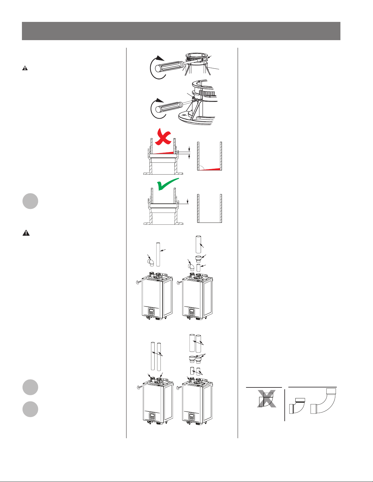
• When inser ng the pipe into the
exhaust/intake port, make sure
that the pipe end is cut straight and
posi oned properly under the o-ring
to seal the connec on fi rmly.
• Improper ven ng of this appliance
can result in excessive levels of
carbon monoxide which can result in
severe personal injury or death.
Vent Piping
Insert 2 in diameter straight
1
pipe fully into the exhaust/
intake connection ports until
fully seated (See Figure 15). The pipes
will insert at a minimum of 1.5 inches.
WARNING: The exhaust vent pipe
connec on to the water heater must
be fl ush to maintain a proper seal.
Check pipe for a 90° edge before
installa on. DO NOT use a fi eld cut
end for the connec on. Failure to
follow can cause carbon monoxide
poisoning or death.
NOTICE: For 3 in Ven ng, install
a 2 in x 3 in increaser to convert
to 3 in ven ng. For low clearance
installa ons, a 2 in long sweep elbow
may be used. Then 12 in max length
straight pipe may be used to fi t a 2 in
x 3 in increaser.
Air Intake for Power Vent Installs:
Insert the male end of a 2 in long
sweep street elbow into the heater’s
air intake port.
Use a screwdriver to tighten
2
the clamp. (See Figure 15)
Power Vent (PV)
2 in Pipe
Direct Vent (DV)
Intake Port
Self-Tapping Screw
Pipe end
ŶŽƚŇƵƐŚ
ǁŝƚŚďĂƐĞ
Pipe end
ŝƐŇƵƐŚ
ǁŝƚŚďĂƐĞ
2 in Pipe
2 in Pipe
džŚĂƵƐƚ
Port
2 in Pipe
Intake
Port
Clamp
džŚĂƵƐƚsĞŶƚ
Pipe
Not a
90° edge
džŚĂƵƐƚsĞŶƚ
Pipe
90° edge
3 in Pipe
2 in to 3 in
Adapter
2 in Pipe
3 in Pipe
2 in to 3 in
Adapter
2 in Pipe
džŚĂƵƐƚ
Exhaust Vent for
Indoor Installa on
ABS, PVC, CPVC or
polypropylene vent
The Indoor model can be vented with
ABS, PVC, CPVC, or polypropylene
(temperature rated up to 149°F).
In Canada, plas c ven ng must be
cer fi ed to ULC S636.
• The maximum length of exhaust
ven ng or intake piping shall not
exceed the lengths listed in Table 8.
• Do not use more than fi ve elbows in
a vent system. For every 90 degree
elbow added, deduct fi ve feet and
45 degree elbows count as 2.5 . If
an elbow(s) is used in the vent system, deduct each equivalent length
from the Max. vent length to decide
the total vent length.
• When the horizontal vent run
exceeds 5 (1.5 m), support the
vent run at 3 (0.9 m) intervals with
overhead hangers.
• In areas of high rainfall the installa on of the rain trap may be necessary.
• Slope horizontal ven ng sec ons
1/4 in (6 mm) upwards for every 12
in (305 mm) toward the termina on or according to local and state
codes, or in the absence of local or
state/provincial codes, the current
edi on of the ANSI Z223.1/NFPA 54,
Na onal Fuel Gas Code or B149.1,
Natural gas and propane installa on
code.
• Do not use ght 90° elbows. Stan-
dard and long sweep elbows are
acceptable. See Figure 16.
Not Recommeded
Recommended
Use the supplied self-tapping
3
screws to secure the venting
to the intake and exhaust
ports as shown in the image on the
right. (See Figure 15)
Figure 15 - Vent Pipe Installa on
Residen al Gas Tankless Water Heater Use and Care Guide • 23
90° Vent
Elbow
Figure 16 - Correct/Incorrect Elbows
90° Sweep
Elbow
90° Long
Sweep
Elbow
Page 24
INSTALLATION
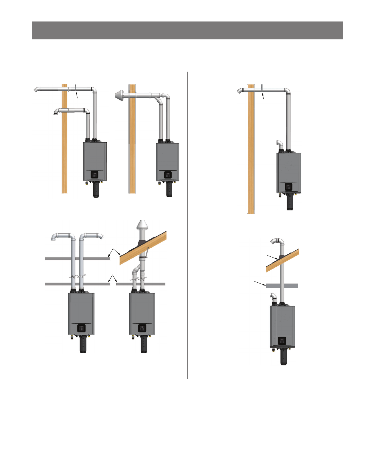
Typical Ven ng Confi gura ons:
The following are typical ven ng confi gura ons examples.
Direct Vent Horizontal Installa on Examples
Hanger
Direct Vent Ver cal Installa on Examples
Roof
Power Vent Horizontal Installa on Example
Hanger
Power Vent Ver cal Installa on Example
Roof
Flashing
Fire Stop
Figure 17 - Vent Confi gura on Examples for Direct Vent
Fire
Stop
Figure 18 - Vent Confi gura on Examples for Power Vent
24 • Residen al Gas Tankless Water Heater Use and Care Guide
Page 25
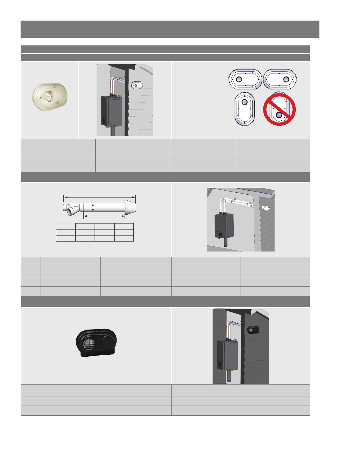
Table 9: - Vent Termina ons
INSTALLATION
LOW PROFILE TERMINATION
If used in ver cal
posi on, the
exhaust port must
be placed in the
upper side.
Vent Pipe Size PVC Kit Number IPEX PVC Part Number
IPEX System 1738®
PVC Part Number
2 in 100187903 196984 397984
3 in 100187887 196985 397985
CONCENTRIC TERMINATION
A
C
B
ABC
FGV 2" 29” 16" 2"
FGV 3" 36” 20" 3"
Vent
Pipe
Size
PVC Kit Number
IPEX
PVC Part Number
IPEX System 1738®
PVC Part Number
IPEX System 636®
CPVC Part Number
2 in 100112869 196005 397005 197040
3 in 100112163 196006 397006 197006
POLYPROPYLENE CONCENTRIC TERMINATION
Vent Pipe Size Centrotherm Part Number
2 in ISLPT0202
3 in ISLPT0303
Residen al Gas Tankless Water Heater Use and Care Guide • 25
Page 26
INSTALLATION
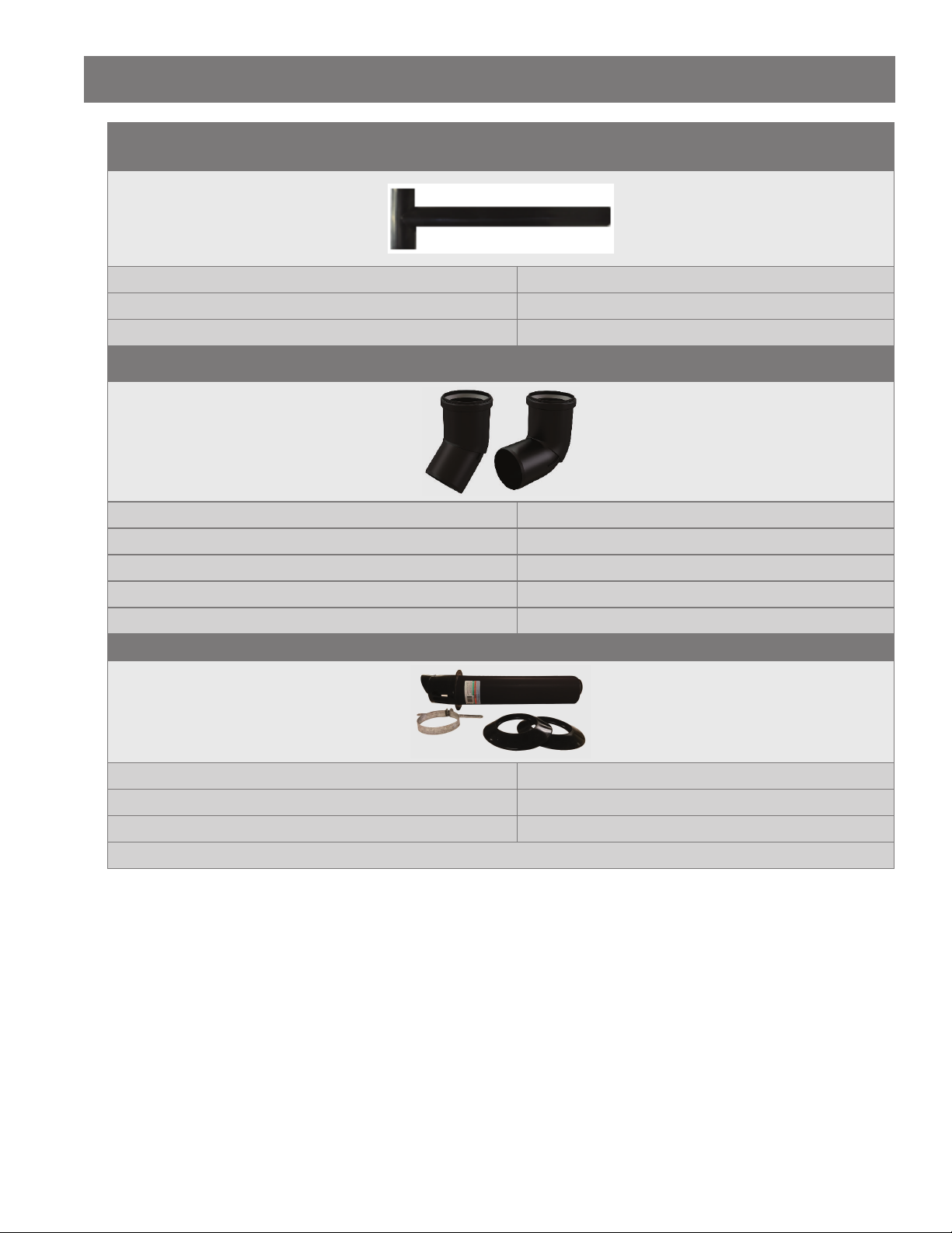
Vent Pipe Size Centrotherm Part Number
Vent Pipe Size Centrotherm Part Number
POLYPROPYLENE TERMINATION TEE
2 in ISTT0220
3 in ISTT0320
POLYPROPYLENE RADIUS ELBOWS
2 in 45° EXHAUST ELBOW ISELS0245UV
3 in 45° EXHAUST ELBOW ISELS0345UV
2 in 87° INLET ELBOW ISELS0287UV
3 in 87° INLET ELBOW ISELS0387UV
POLYPROPYLENE CONCENTRIC WALL TERMINATION
Vent Pipe Size Centrotherm Part Number
2 in ICWT242*
3 in ICWT352*
*Consult the vent manufacturer for approved concentric / twin pipe adaptors
26 • Residen al Gas Tankless Water Heater Use and Care Guide
Page 27
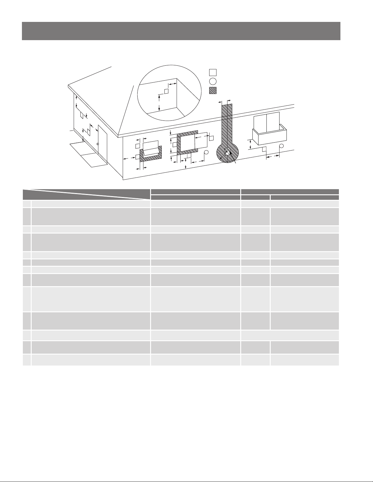
Vent Termina on Clearances
INSTALLATION
Inside corner
detail
G
V
D
E
V
B
V
L
V
V
F
C
Operable
B
Fixed
closed
A
B
Operable
V
B
V
B
A
Canada Installa ons
Direct vent and other than direct vent Direct vent Other than direct vent
Fixed
closed
J
V
= Vent terminal
X
= Air supply inlet
= Area where the terminal
ŝƐŶŽƚƉĞƌŵŝƩĞĚ
H
B
V
X
I
1
M
V
K
Regulator/Gas meter
vent outlet
US Installa ons
X
2
A Clearance above grade, veranda, porch, deck, or balcony 1 ft (30 cm) 1 ft (30 cm)
B Clearance to window or door that may be opened 3 f t (91 cm)
1 ft
(30 cm)
4 ft (1.2 m) below or to side
of opening; 1 ft (30 cm)
above opening
C Clearance to permanently closed window 0 0 0
Vertical clearance to ventilated soffit located above
D
the vent terminator within a horizontal distance of 2
3 ft (91 cm) 3 ft (91 cm) 3 ft (91 cm)
feet (61cm) from the center line of the termination
E Clearance to unventilated soffit 3 ft (91 cm) 3 ft (91 cm) 3 ft (91 cm)
F Clearance to outside corner 2 ft (61 cm) 2 ft (61 cm) 2 ft (61 cm)
G Clearance to inside corner 2 ft (61 cm) 2 ft (61 cm) 2 ft (61 cm)
Clearance to each side of center line extended above
H
meter/regulator assembly
3 ft (91 cm) * *
Above a regulator within 3 ft (91 cm)
horizontally of the vertical center
I Clearance to service regulator vent outlet
line of the regulator vent outlet to a
**
maximum vertical distance of 15 ft (4.5
m)
Clearance to non-mechanical air supply inlet to
J
a building or the combustion air inlet to any other
3 ft (91 cm)
appliance.
K Clearance to mechanical air supply inlet 6 ft (183 cm)
Clearance above paved sidewalk or paved driveway
L
located on public property
7 ft (213 cm)**
M Clearance under veranda, porch deck, or balcony 1 ft (30 cm)***
1 ft
(30 cm)
7 ft
(213 cm)
1 ft
(30 cm)***
4 ft (1.2 m) below or to side
of opening; 1 ft (30 cm)
above opening
3 ft (91 cm) above if within
10 ft (3 m) horizontally.
7 ft (213 cm)
1 ft (30 cm)***
*Clearance in accordance with local installation codes and the requirements of the gas supplier.
**A vent shall not terminate directly above a sidewalk or paved driveway that is located between two single family dwellings and serves
both dwellings.
***Permitted only if veranda, porch, deck, or balcony is fully open on a minimum of two sides beneath the floor.
The vent for condensing water heaters shall not terminate:
• over public walkways; or
• near soffi t vents or crawl space vents or other areas where condensate or vapor could create a nuisance or hazard or cause property dam-
age; or
• where condensate vapor could cause damage or could be detrimental to the opera on of regulators, relief valves, or other equipment.
Notes:
1) In accordance with the current CSA B149.1, Natural Gas and Propane Installation Code
2) In accordance with the current ANSI Z223.1/NFPA 54, National Fuel Gas Code
Residen al Gas Tankless Water Heater Use and Care Guide • 27
Page 28
INSTALLATION
Clearances for Sidewall
Termina ons
WARNING! Improper installa on
can result in carbon monoxide
poisoning or death. Follow all local
and na onal codes in regards to
proper termina on clearances.
In the absence of such codes, the
clearances below can be used as
guidelines. Local codes supersede
these guidelines
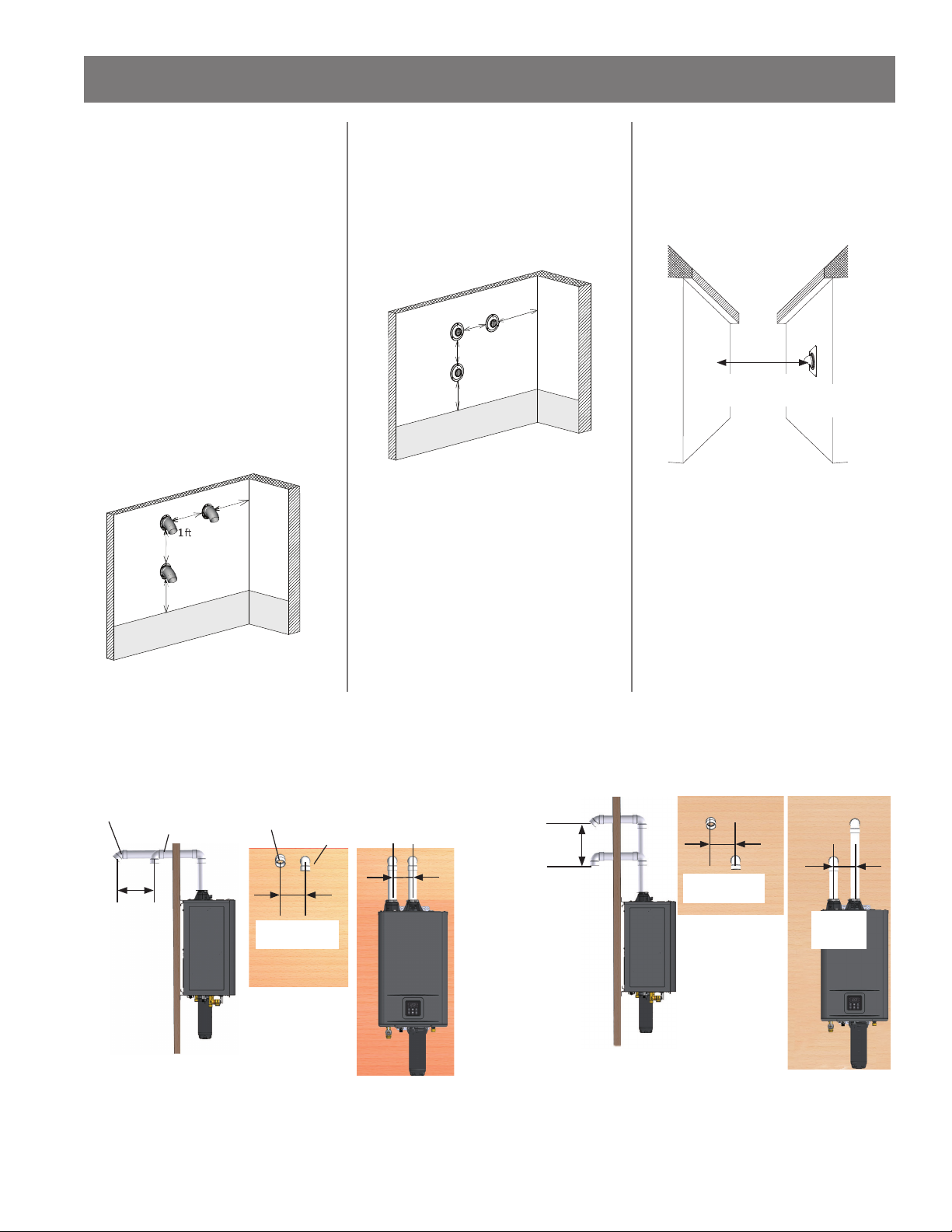
Mul ple Sidewall Termina ons
An exhaust termina on must be at
least: 1 (305 mm) from another
exhaust termina on and 2 (610
mm) from an inside corner
ϮŌ
;ϲϭϬŵŵͿ
ŵŝŶ
ŵŝŶ
ϭŌ
ŵŝŶ
džŚĂƵƐƚ
dĞƌŵŝŶĂƟŽŶ
;ϯϬϱŵŵͿ
;ϯϬϱŵŵͿ
Mul ple DV Sidewall
Termina ons
A direct vent (DV) termina on must
be at least:
• 1 (305 mm) from other DV termi-
na ons
• 2 (610 mm) from an inside corner
Combined
ŝŶƚĂŬĞĂŶĚ
ĞdžŚĂƵƐƚ
ƚĞƌŵŝŶĂƟŽŶ
Figure 20 - Mul ple DV Sidewall Termina ons
(305 mm)
(305 mm)
ŶƟĐŝƉĂƚĞĚ^ŶŽǁůĞǀĞů
ϭŌ
min.
ϭŌ
min.
ϮŌ
(610 mm)
min.
Inside
corner
Exhaust and/or direct vent sidewall
termina ons should be at least 2
(610 mm) away from an opposite
surface/wall. Do not place the
termina on directly in front of an
opening into a building.
2 ft (610 mm)
min.
Figure 21 - Sidewall Termina on Minimum
Distance to another Structure.
Exhaust
termination
ŶƟĐŝƉĂƚĞĚ^ŶŽǁůĞǀĞů
Figure 19 - Mul ple Sidewall Termina ons
/ŶƐŝĚĞ
ĐŽƌŶĞƌ
For direct vent sidewall termina ons that use two separate penetra ons for the intake and exhaust, keep the termina on
clearances shown in the diagrams below.
min.
Exhaust
Intake
Exhaust
Intake
0.5 ft
(159 mm) min.
0.5 ft
(159 mm)
min.
Exhaust
1 ft (305 mm)
min.
Intake
Exhaust
Intake
0.5 ft
(159 mm) min.
0.5 ft
(159 mm)
min.
1 ft (305 mm)
Figure 22 - Direct Vent Sidewall Termina ons
28 • Residen al Gas Tankless Water Heater Use and Care Guide
Page 29
INSTALLATION
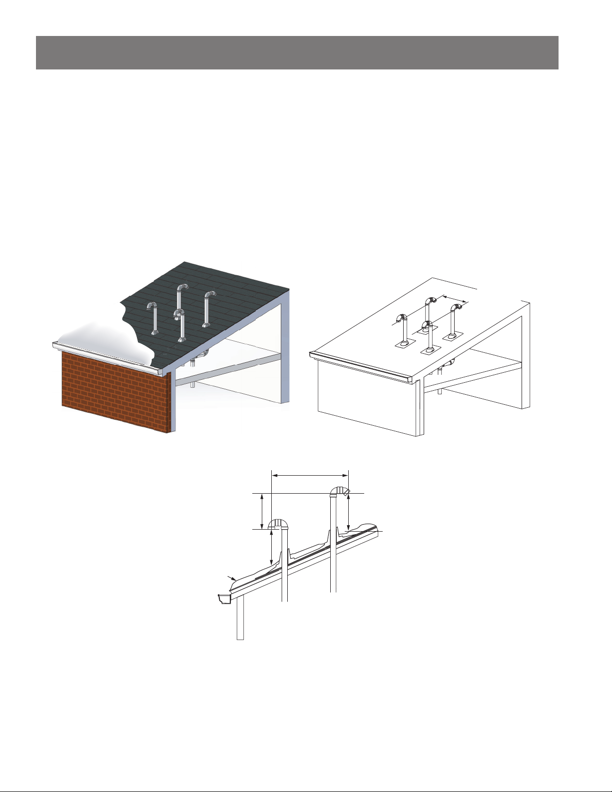
Clearances for Roo op
Termina ons
WARNING! Follow all local and
na onal codes in regards to proper
termina on clearances. In the
absence of such codes, the clearances
below must be met. Local codes
supersede these clearances. Failure
to observe this warning may result in
severe personal injury or death.
NOTICE: Canadian requirements diff er
from the guidelines in this sec on.
Typical PDV Installation
Anticipated Snow Level
In Canada, follow the current edi on
of B149.1, Natural gas and propane
installa on code as well as local
and provincial codes. Contact your
local code enforcement agency for
direc on.
• Exhaust termina ons must be at
least 1 (305 mm) away from any
obstruc ons.
• Minimum spacing between mul ple
terminals:
• Intake terminals: 1 (305 mm)
spacing between each
• Exhaust terminals: 1 (305 mm)
spacing between each
• The exhaust termina on must be
a horizontal distance of at least 2
(610 mm) from a wall or surface
unless specifi ed diff erently by local
code.
• Failure to observe this warning may
result in severe personal injury or
death.
1 ft (305 mm) min.
ISO VIEW
3 ft (914 mm) min.
1 ft (305 mm) min.
1 ft (305 mm)
min. above anticipated
snow level.
* Anticipated Snow
Level.
Air Intake
&ŽůůŽǁĂůůůŽĐĂůĂŶĚŶĂƟŽŶĂůĐŽĚĞƐŝŶƌĞŐĂƌĚƐƚŽƉƌŽƉĞƌƚĞƌŵŝŶĂƟŽŶĐůĞĂƌĂŶĐĞƐ/ŶƚŚĞĂďƐĞŶĐĞ
ŽĨƐƵĐŚĐŽĚĞƐƚŚĞĐůĞĂƌĂŶĐĞƐďĞůŽǁŵƵƐƚďĞŵĞƚ>ŽĐĂůĐŽĚĞƐƐƵƉĞƌƐĞĚĞƚŚĞƐĞĐůĞĂƌĂŶĐĞƐ
Figure 23 - Pitched roof with mul ple ver cal termina ons.
1 ft (305 mm)
min. above anticipated snow level.
SIDE VIEW
Exhaust Vent
Residen al Gas Water Heater Use and Care Guide • 29
Page 30
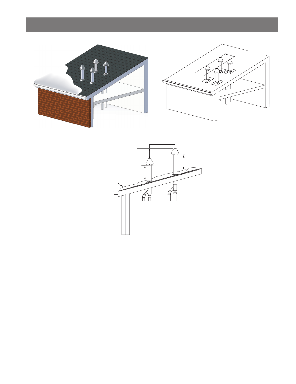
INSTALLATION
Typical PDV Concentric Installation
Anticipated Snow Level
1 ft (305 mm) min.
FRONT
1 ft (305 mm) min.
1 ft (305 mm) min.
above anticipated snow level.
* Anticipated Snow
Level (ASL).
FRONT
ISO VIEW
3 ft (914 mm) min.
Air Intake
Exhaust Vent
Air Intake
SIDE VIEW
FRONT
1 ft (305 mm) min.
above anticipated snow level.
Exhaust Vent
&ŽůůŽǁĂůůůŽĐĂůĂŶĚŶĂƟŽŶĂůĐŽĚĞƐŝŶƌĞŐĂƌĚƐƚŽƉƌŽƉĞƌƚĞƌŵŝŶĂƟŽŶĐůĞĂƌĂŶĐĞƐ/ŶƚŚĞĂďƐĞŶĐĞ
ŽĨƐƵĐŚĐŽĚĞƐƚŚĞĐůĞĂƌĂŶĐĞƐďĞůŽǁŵƵƐƚďĞŵĞƚ>ŽĐĂůĐŽĚĞƐƐƵƉĞƌƐĞĚĞƚŚĞƐĞĐůĞĂƌĂŶĐĞƐ
Figure 24 - Pitched roof with mul ple ver cal concentric termina ons.
30 • Residen al Gas Water Heater Use and Care Guide
Page 31
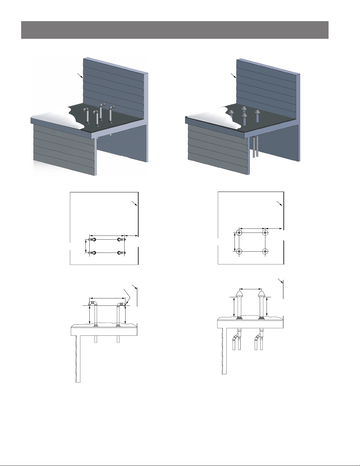
Typical Flat Roof Terminations
(Both Single and Multiple)
Wall Wall
INSTALLATION
Anticipated Snow Level
FRONT
FRONT
1 ft (305 mm) min.
min. above anticipated
FRONT
1 ft (305 mm)
snow level.
ISO VIEW
Wall Wall
TOP VIEW
3 ft (914 mm) min.
Exhaust Vent
3 ft (914 mm) min.
Wall
2 ft (610 mm) min.
from wall or surface.
1 ft (305 mm)
min. above anticipated
snow level.
SIDE VIEW
Anticipated Snow Level
FRONT
FRONT
1 ft (305 mm) min.
1 ft (305 mm)
min. above anticipated
snow level.
FRONT
ISO VIEW
TOP VIEW
3 ft (914 mm) min.
2 ft (610 mm) min.
from wall or surface.
Wall
3 ft (914 mm) min.
1 ft (305 mm)
min. above anticipated
snow level.
SIDE VIEW
Air Intake
Exhaust Vent
Air Intake
Air Intake
Exhaust Vent
Exhaust Vent
&ŽůůŽǁĂůůůŽĐĂůĂŶĚŶĂƟŽŶĂůĐŽĚĞƐŝŶƌĞŐĂƌĚƐƚŽƉƌŽƉĞƌƚĞƌŵŝŶĂƟŽŶĐůĞĂƌĂŶĐĞƐ/ŶƚŚĞĂďƐĞŶĐĞ
ŽĨƐƵĐŚĐŽĚĞƐƚŚĞĐůĞĂƌĂŶĐĞƐďĞůŽǁŵƵƐƚďĞŵĞƚ>ŽĐĂůĐŽĚĞƐƐƵƉĞƌƐĞĚĞƚŚĞƐĞĐůĞĂƌĂŶĐĞƐ
Figure 25 - Flat roof with mul ple ver cal termina ons.
Residen al Gas Tankless Water Heater Use and Care Guide • 31
Page 32
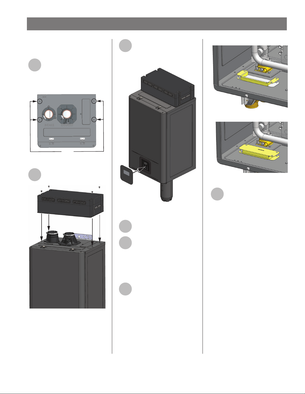
INSTALLATION
Screws
Exhaust Ven ng for
Outdoor Installa on
Turn off power and the gas
1
supply to the water heater.
Remove the four screws from
the top plate of the water heater as
shown in the fi gure below.
Figure 26 - Remove top plate screws.
Orient the outdoor vent cap
2
as shown in Figure 27.
Secure the Outdoor Vent Cap
3
to the water heater at each
corner with the screws
removed earlier. See Figure 27.
INDOOR CONFIGURATION
OUTDOOR CONFIGURATION
Figure 29 - Air inlet plate orienta on op ons
Figure 27 - Outdoor Vent Cap secure with
screws.
Figure 28 - Control Panel Cover Plate Install.
A ach the UIM overlay as
4
shown in Figure 28.
Remove the front cover and
5
remove the screw on the top
le holding the computer
board in place, press the locking tab
and pull the computer board towards
yourself to lower it on the hinge to
access the air inlet plate.
Locate the air inlet plate as
6
shown in Figure 29. Remove
and keep the 3 screws
securing it to the base of the water
heater. The plate is color coded and it
should be rotated so that the yellow
side of the plate is rotated up. Secure
with the screws removed earlier.
.
NOTICE: This water heater comes
equipped with a SJWT rated cord
which is weather resistant and rated
for outdoor use. See “Electrical
Connec ons” on page 42.
Connect the water heater to
7
power. See “Electrical
Connec ons” on page 42.
Outdoor Available
Accessories
It is recommended that a Cartridge
Freeze Protec on Kit be installed if
the water heater is installed outside
or in uncondi oned areas subject to
freezing temperatures.
A pipe cover is available and affi xes
to bo om of heater. It protects
plumbing connec ons to the heater
while improving the appearance of
the installa on.
For more informa on see “Available
Accessories” on page 15
32 • Residen al Gas Tankless Water Heater Use and Care Guide
Page 33

INSTALLATION
Gas Supply and Gas
Pipe Sizing
Gas Piping
WARNING! Read the water
heater’s data plate to determine
the type of gas required. Failure to
follow these instruc ons can result
in serious injury or death from
explosion, fi re or carbon monoxide
poisoning.
• Ensure that any and all gas
regulators used are opera ng
properly and providing gas
pressures within the specifi ed
range shown below. Excess gas
inlet pressure may cause serious
accidents.
• The water heater is set only for
Natural Gas at the factory. If your
gas type is Liquid Propane Gas, gas
conversion shall be required with
the included gas conversion kit by a
qualifi ed installer.
Gas piping must be installed according
to local and state/provincial codes,
or in the absence of these codes, the
current edi ons of ANSI Z223.1/NFPA
54, Na onal Fuel Gas Code in the USA
or B149.1, Natural gas and propane
installa on code in Canada.
• DO NOT a ach the gas line to the
water heater un l a er supply line
pressure tes ng has been complet-
ed to avoid any damage to the water
heater.
• The minimum and maximum inlet
gas pressures are:
Table 10: - Inlet Gas Type/Pressure
Natural Gas:
Min 3.5 in W.C. (0.87 kPa)
Max. 10.5 in W.C. (2.62 kPa)
Propane:
Min 8.0 in W.C. (1.99 kPa)
Max. 13.0 in W.C. (3.24 kPa)
local and state/provincial codes, or
in the absence of these codes, the
current edi ons of ANSI Z223.1/
NFPA 54, Na onal Fuel Gas Code in
the USA or B149.1, Natural gas and
propane installa on code in Canada.
Otherwise, fl ow capabili es and
output temperatures will be limited.
• Inlet gas pressures that fall outside
the range of values listed above may
adversely aff ect the performance
of the water heater. These pressures are measured when the water
heater and all other gas appliance(s)
served by the same gas line are in
full opera on.
• Inlet gas pressure must not exceed
the maximum values in Table 10; gas
pressure above the specifi ed range
will cause dangerous opera ng con-
di ons and damage to the unit.
• If the gas supply pressure to the
heater is greater than the specifi ed
maximum, a fi eld-supplied regula-
tor is required. The regulator must
lower the gas pressure within the
approved range.
• Install the gas regulator according
to the manufacturer's instruc ons.
Some manufacturers may require a
certain amount of straight pipe on
the outlet prior to any addi onal
fi ngs.
• The regulator must be sized for the
water heater's minimum to maximum input and provide the specifi ed pressures that are listed on the
ra ng plate.
• In the absence of minimum install
distance stated by the regulator
manufacturer, it is recommended
that there is at least 3 (1 m) of
piping between the regulator outlet
and the water heater's inlet gas
connec on.
Install a full port manual gas
2
shutoff valve between the
water heater and the gas
supply line.
When the gas connections
3
are completed, it is necessary
to perform a gas leak test
either by applying soapy water to all
gas fittings and observing for bubbles
or by using a gas leak detection
device.
• The water heater and its
individual shutoff valve must
be disconnected from the gas
supply piping system during any
pressure tes ng of that system
at test pressures in excess of 1/2
psi (3.5 kPa).
• The water heater must be isolated from the gas supply piping
system by closing its individual
manual shutoff valve during
any pressure tes ng of the gas
supply piping system at test
pressures equal to or less than
1/2 psi (3.5 kPa).
Always purge the gas line of
4
any debris and/or water
before connec ng to the gas
inlet.
Size the gas pipe appropriately to
supply the necessary volume of gas
pressure, and allowable pressure drop
required for the water heater using
gas piping manufacturer instruc ons,
Gas Connec ons
Use a 1/2 in union to connect
1
gas piping to the water
heater's 1/2 in male NPT
connection.
Residen al Gas Water Heater Use and Care Guide • 33
Page 34
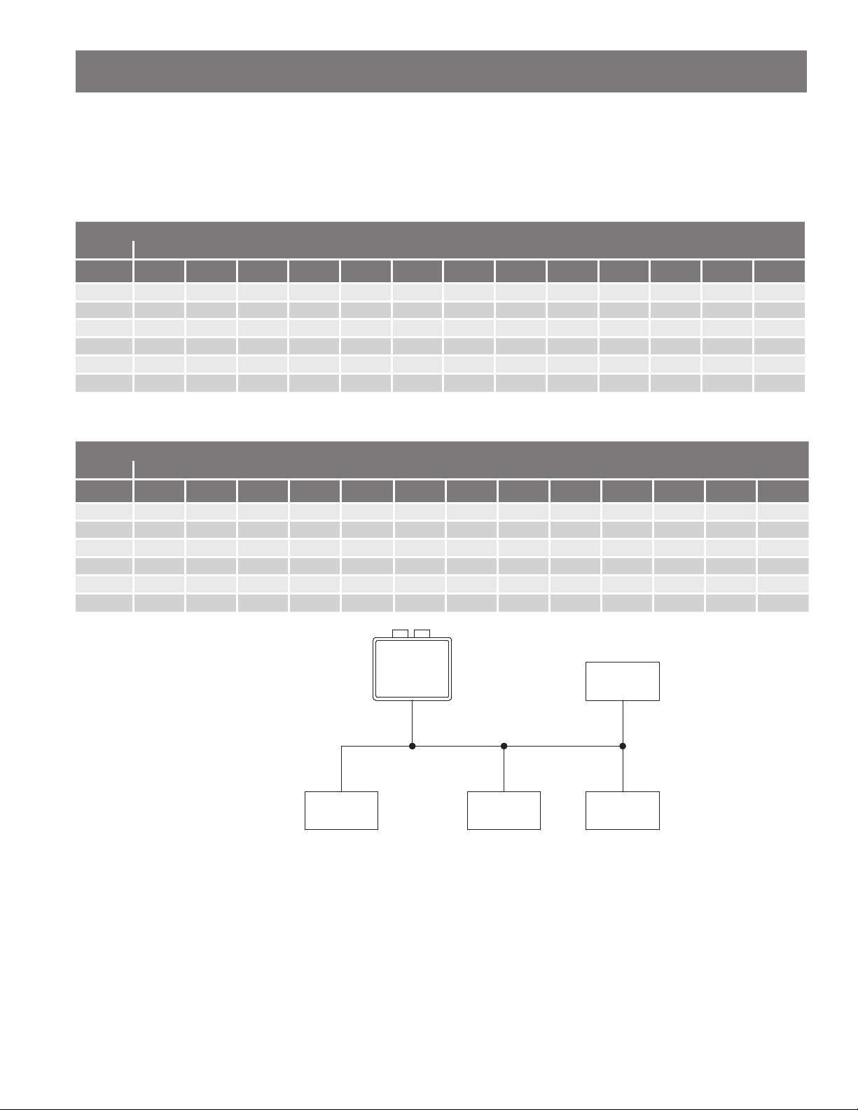
INSTALLATION
Natural Gas Supply Piping
Maximum delivery Capacity in Cubic Feet of Gas per Hour (based on IPS Pipe carrying Natural Gas with 0.60 Specifi c Gravity with
a Pressure Drop of 0.5 in W.C.).
Based on Energy Content of 1,000 BTU/ 3: The water heater requires 199 3/h for the THR-199, 180 3/h for the THR-180, 160
3/h for the THR-160.
The following tables are from ANSI Z223.1/NFPA 54. (Unit: Cubic feet per hour)
Table 11: Natural Gas Table
Pipe Size Length
Diameter
1/2 in 172 118 95 81 72 65 60 56 52 50 44 40 34
3/4 in 360 247 199 170 151 137 126 117 110 104 92 83 71
1 in 678 466 374 320 284 257 237 220 207 195 173 157 134
1-1/4 in 1,390 957 768 657 583 528 486 452 424 400 355 322 275
1-1/2 in 2,090 1,430 1,150 985 873 791 728 677 635 600 532 482 412
2 in 4,020 2,760 2,220 1,900 1,680 1,520 1,400 1,300 1,220 1,160 1,020 928 794
10 ft
(3.0 m)
Maximum Capacity of Propane (LP) Based on 11 in W.C. supply pressure at a 0.5 in W.C. pressure drop. (Unit: kBTU per hour)
Table 12: Propane Gas Table
Pipe Size Length
Diameter
1/2 in
3/4 in 567 393 315 267 237 217 196 185 173 162 146 132 112
1 in 1,071 732 590 504 448 409 378 346 322 307 275 252 213
1-1/4 in 2,205 1,496 1,212 1,039 913 834 771 724 677 630 567 511 440
1-1/2 in 3,307 2,299 1,858 1,559 1,417 1,275 1,181 1,086 1,023 976 866 787 675
2 in 6,221 4,331 3,465 2,992 2,646 2,394 2,205 2,047 1,921 1,811 1,606 1,496 1,260
10 ft
(3.0 m)
268 184 148 126 112 101 93 87 82 77 68 62 53
20 ft
(6.1 m)
20 ft
(6.1 m)
30 ft
(9.1 m)
30 ft
(9.1 m)
40 ft
(12.2 m)
40 ft
(12.2 m)
50 ft
(15.2 m)
60 ft
(18.3 m)
70 ft
(21.3 m)
80 ft
(24.4 m)
Propane (LP) supply piping
50 ft
(15.2 m)
60 ft
(18.3 m)
70 ft
(21.3 m)
80 ft
(24.4 m)
90 ft
(27.4 m)
90 ft
(27.4 m)
100 ft
(30.5 m)
100 ft
(30.5 m)
125 in
(38.1 m)
125 ft
(38.1 m)
150 in
(45.7 m)
150 ft
(45.7 m)
200 in
(61.0 m)
200 ft
(61.0 m)
Gas sizing example
(Natural Gas)
5' (1.5 m) Length
1-1/4" Pipe size
5' (1.5 m)Length
1-1/4" Pipe size
Gas meter
Water heater
199,000 BTU/h
10' (3 m)Length
1/2" Pipe size
A
10' (3 m )Length
1" Pipe size
15' (4.6 m)Length
B
10' (3 m)Length
3/4" Pipe size
Furnace
120,000 BTU/h
1" Pipe size
Dryer
35,000 BTU/h
10' (3 m)Length
1/2" Pipe size
15' (4.6 m)Length
1/2" Pipe size
C
Range
65,000 BTU/h
Based on Energy Content of 1,000 BTU/ 3:
Divide each appliance's BTU/h requirement by 1,000 BTU/ 3 to get the appliance's 3/h requirement.
Take into account the distance the appliance is from the gas meter, look in the above gas chart to properly size the line.
For sec ons of the gas line supplying gas to more than one appliance (Ex: Point A to Point B), add up the cubic per hour
requirements of the appliances that are being supplied by that sec on, and size to the farthest appliance.
For Example: The sec on from A to B supplies gas to the furnace, range and dryer. Adding up the BTU/h requirements and
dividing by 1,000 yields a 3/hr requirement of 220 3 of gas per hour. The farthest appliance is the range, which is 50 away
from the meter. Looking at the above chart, and under the column of 50 , Sec on A to B needs to be 1 in in order to supply
220 3.
34 • Residen al Gas Tankless Water Heater Use and Care Guide
Page 35

INSTALLATION
Gas Conversion
Instruc ons
WARNING! An improper fi eld
conversion could cause poten ally
dangerous condi ons that may
cause an explosion or fi re resul ng
in property damage, bodily injury or
both.
This water heater is confi gured
for Natural Gas from the factory.
However, if a fi eld conversion to
Propane Gas is necessary, the
conversion kit and instruc ons
supplied with the water heater, and
must be used and installed by a
qualifi ed service agency.
Before you install the components in
this Propane Gas conversion kit, verify
the type of gas that will be used to
fuel the unit.
Water Connec ons
WARNING! Do not use this appliance
if any part has been under water.
Immediately contact a qualifi ed
installer or service agency to replace
a fl ooded water heater. Do not
a empt to repair the unit! It must be
replaced!
NOTICE: Do not reverse the hot
outlet and cold inlet connec ons to
the water heater. If you reverse the
connec ons, the water heater will not
ac vate properly.
Determine the type of water pipes in
your home. Use fi ngs appropriate
for the type of pipe in your home
(copper, CPVC, or PEX). Do not
use iron or PVC pipe – they are
not suitable for potable water. All
pipes, pipe fi ngs, valves and other
components, including soldering
materials, must be suitable for
potable water systems. Also, an
automa c air vent or air separator
must be installed when the water
heater operates in a closed loop
system such as a recircula on
system. Trapped air bubbles in the
water system can cause a pump to
cavitate or damage the water heater's
heat exchanger. This equipment
must be installed according to its
manufacturer's instruc ons.
• A manual shutoff valve must be
installed on the cold water inlet to
the water heater between the main
water supply line and the water
heater.
• A thermal expansion tank or code
approved device to handle thermal
expansion must be and charged
to match the supply pressure as
per the thermal expansion tank
manufactures instruc on.
• Connect the cold water supply using
3/4 inch Na onal Pipe Thread “NPT”
to the fi ng marked COLD.
• For ease of removing the water
heater for service or replacement,
connect the water pipes with a
union. We recommend using a dielectric-type union (available at your
local plumbing supplier). Dielectric
unions can help prevent corrosion
caused by ny electric currents
common in copper water pipes and
can help extend the life of the water
heater.
• Connect the hot water supply using
3/4 inch NPT to the fi ng marked
HOT. Follow the same connec on
guidelines as for the cold water
supply.
• In addi on, a manual shutoff valve is
also recommended on the hot water
outlet.
• Double check to make sure the hot
and cold water pipes are connected
to the correct hot and cold water
fi ngs on the water heater.
• If needed, install (or adjust) the
home’s Pressure Reducing Valve.
• Before installing the water heater,
fl ush the water line to remove all
debris, and a er installa on is com-
plete, purge the air from the line.
Failure to do so may cause damage
to the heater.
• There is a wire mesh fi lter within
the cold inlet to trap debris from entering your heater. This will need to
be cleaned periodically to maintain
op mum fl ow.
• Install insula on (or heat tape) on
the water pipes especially if the
indoor installa on area is subject to
freezing temperatures. Insula ng
the hot water and return pipes will
reduce heat loss.
• If water hammer is evident install
water hammer arrestors on the inlet
side.
• A drain pan, or other means of
protec on against water damage, is
recommended to be installed under
the water heater in case of leaks.
IF YOU HAVE COPPER PIPES:
If your home has copper water
pipes, you can solder the water pipe
connec ons or use compression
fi ngs which don’t require soldering.
Compression fi ngs are easier to
install than soldering pipe. Check with
local plumbing offi cials to determine
what types of pipe materials are
suitable for your loca on. Do not use
lead-based solder.
NOTICE: Do not solder pipes while
they are a ached to the water
heater. The water heater contains
non-metallic parts which could be
damaged. The proper way to connect
the water heater to copper water
pipes is as follows:
• Solder a short length of pipe (about
a foot or so) to a threaded adapter
using only 95/5 n an mony or
equivalent solder.
• A ach the threaded adapters to the
water heater’s connec ons (using
thread sealant tape or pipe joint
compound). Connect the home’s
water pipes by soldering, keeping
the connec ons at the water heater
cool with wet rags.
Residen al Gas Tankless Water Heater Use and Care Guide • 35
Page 36
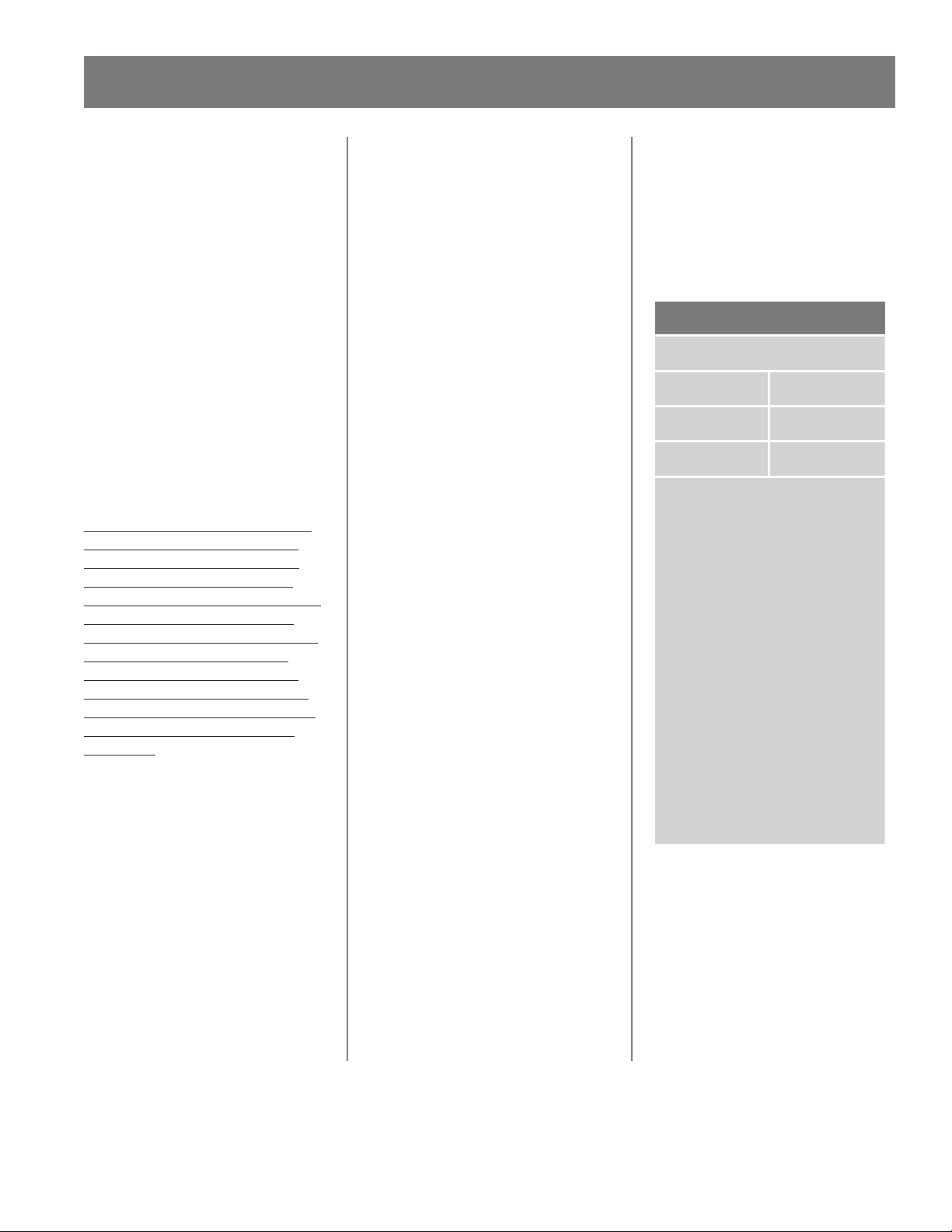
INSTALLATION
Recircula on
Internal Pump
This water heater comes with an
integrated recircula on pump, which
is deac vated by default from the
factory. The water heater has 3
recircula on mode op ons:
• Recircula on with a dedicated
return line
• Crossover recircula on mode
• On-Demand mode compliant with
California’s Title 24
Details of the opera on are listed
below. In each mode, the heater’s
pump only operates when there is no
demand from the home’s fi xtures. The
pump stops when demand is detected
from a plumbing fi xture.
The internal recircula on pump can
compensate for various plumbing
confi gura ons and the associated
pressure drops, balancing power
usage against the target recircula on
fl ow rate. The so ware has been
op mized with a default power level
to operate in the most common
installa ons delivering 1.0 gpm in
the Dedicated Return Line mode or
0.5 gpm in a Crossover Recircula on
mode while maintaining effi cient
opera ons.
NOTE: If a dedicated return line is
installed, a check valve is necessary on
the return line upstream of the tee to
the cold water supply line. See piping
layout in Figure 30 on page 37.
• Recircula on with a Dedicated
Return Line - In this mode, the
water heater will operate the
pump in order to keep your water
lines warm, reducing the me it
takes for the hot water to arrive at
the fi xture. The user can con Two
Pump Timer ON periods where the
heater will operate the pump. It
is recommended to set the Pump
Timers to ON during mes when
the home is occupied. The water
heater will operate as an ondemand water heater during Pump
Timer Off periods, though there
may be a delay ge ng hot water to
the fi xture. See “Se ng the Pump
Timers” on page 55 to set the
Pump Timers.
• Crossover Valve Mode - In this
mode, a “crossover” valve is typically installed at the home’s furthest
fi xture. This valve will use the
home’s cold water line to act as the
return line. The se ngs on the valve
are dependent on the manufacturer.
For example the typical opera on is
as follows; the crossover valves have
a type of thermal valve that will
open up when the water temperature on the hot side drops below
95°F (35°C) and will close when the
temperature reaches 105°F (40.5°C).
NOTICE: These temperature values
may vary from manufacturer to
manufacturer. Refer to Tables 20
and 21 to set the Crossover Valve
Recircula on mode and the Pump
Timers. For manufacturer recommended crossover valve see “Available Accessories” on page 15.
NOTICE: Func on/compa bilty may
vary with other crossover valves.
• On-Demand Mode - In this mode
the pump will only operate when
ac vated by the user through one
of the wireless push bu ons. A
Remote Recircula on Kit is required
see “Available Accessories” on
page 15. This kit consists of one
receiver wired to the water heater
and at least one push bu on.
The receiver can pair with up to
30 push bu ons. Instruc ons
are provided with the receiver
kit. This mode is compliant with
California’s Title 24 Code. In this
mode, the pump will run un l the
inlet water temperature reaches
the deac va on temperature set in
mode A04 for Recircula on with a
Dedicated Return Line or when the
crossover valve closes if in Crossover
Recircula on. The pump will stop if
it is s ll running a er 5 minutes.
Table 13: Maximum Pipe Length
Hot Water supply line and
Dedicated Return line
Pipe Diameter Pipe Length
3/4 in 500 ft (152.4 m)
1/2 in 200 ft (61 m)
NOTE: These are equivalent
lengths that includes head loss
for elbows, tees, unions, etc
for smooth wall copper tube.
Other water tube materials
have diff erent head loss
characteris cs. When other
materials are used, the installer
shall consult with the water
tube manufacturer to conduct
a head loss calcula on to make
sure the installed pump will fl ow
at least 2 gpm. Please refer to
the manufacturer’s specifi ca on
sheet for pump head loss
informa on. An addi onal pump
may be necessary for circula on
systems with longer equivalent
pipe lengths.
External Pump
When installing an external
recircula on pump, care must be
taken to properly size the pump
for the applica on. Sizing must
be performed by the installing
contractor or engineer. The following
requirements need to be observed
when sizing:
• Size the recircula on pump to fl ow
36 • Residen al Gas Tankless Water Heater Use and Care Guide
Page 37
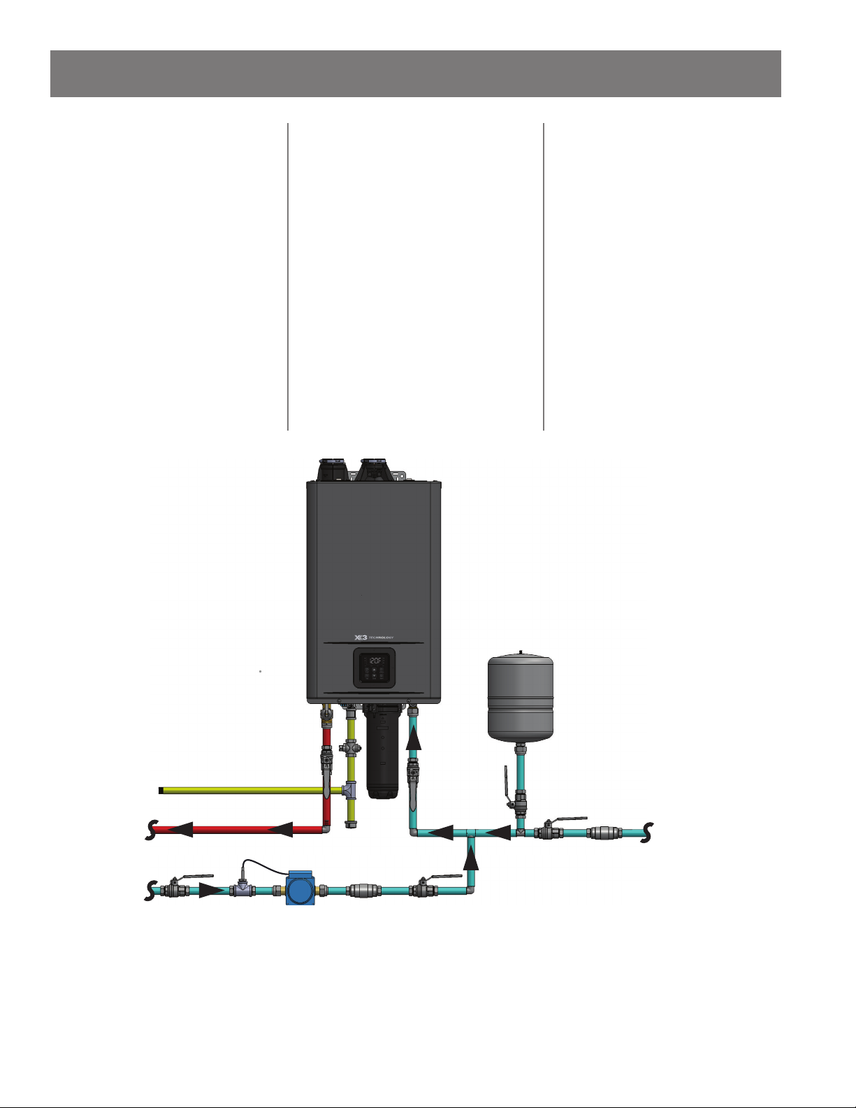
INSTALLATION
no less than 2 gpm (7.6 l/m) and
no more than 4 gpm (15.1 l/m) per
ac vated heater. The manufacturer’s
suggested fl ow rate is 3 gpm (11.4
l/m). Refer to the water heater’s
pressure drop chart on its specifi ca-
on sheet for losses at other fl ow
rates. Head loss at 3 gpm is approximately 16.9 . of head (7.3 psi) The
pump should be controlled by a fi eld
supplied aquastat with immersion
probe and an adjustable diff eren al.
The minimum suggested diff eren al
is 15°F (8.3°C). NOTE: Running the
pump con nuously will reduce the
warranty of the water heater.
• An air elimina on device is suggest-
ed to remove air from the piping
system. Air may cause the recircu-
la on pump to cavitate and may
reduce the water fl ow rate. These
items should be installed per the
manufacturer’s instruc ons.
The installer will need to consider
the size of water tubing, material
type, and fi ngs when determining
the pressure drop of the system to
size the recircula on pump. Note
that these characteris cs vary for
each tubing material of the same
nominal size. Refer to the water
tubing manufacturer for pressure drop
informa on that is needed to size the
recircula on pump.
Below is a suggested piping
diagram. Check with local codes and
ordinances for addi onal installa on
requirements. Refer to the water
heater manufacturer’s website for
addi onal layouts.
Thermosta c mixing valves may be
used with tankless water heaters.
Consult with the mixing valve
manufacturer for the appropriate
mixing valve for the applica on. Refer
to the thermosta c mixing valve
manufacturer for proper installa on
when recircula on is in use.
To reduce the risk of scalding,
install Thermosta c Mixing Valves
(temperature limi ng valves) at each
point of use.
GAS
HOT WATER TO FIXTURES
TEMP. PROBE
PUMP
BUILDING RETURN
SHUT OFF
VALVE
Figure 30 - Recircula on Loop Typical Confi gura on
Residen al Gas Water Heater Use and Care Guide • 37
EXPANSION
TANK
CHECK
VALVE
COLD
WATER
SUPPLY
Page 38
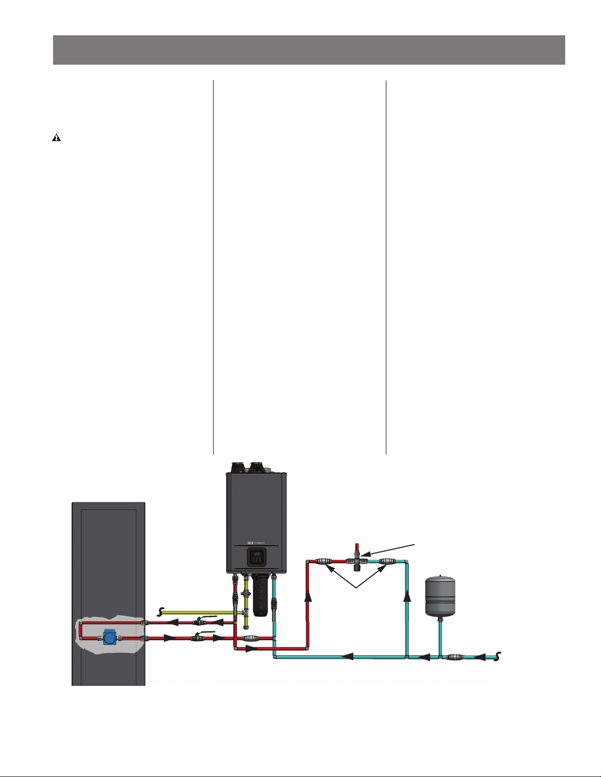
INSTALLATION
Combina on Potable
Water and Space
Hea ng
WARNING! This water heater
is suitable for combina on water
(potable) hea ng & space hea ng,
and not suitable for space hea ng
applica ons only.
• This water heater shall not be
connected to any hea ng system
or component(s) previously used
with non-potable water where
any chemicals were added to the
water hea ng appliances.
• Toxic chemicals used in boiler
treatments such as alcohol, glycerol, and glycol groups must not be
introduced into the water system.
• When the system requires water
for space hea ng at temperatures
higher than required for other
uses, thermosta c mixing valves
must be installed at each pointof-use. Water temperatures over
125°F (52°C) can cause severe
burns instantly or death from
scalding. Failure to observe these
warnings could result in severe
personal injury or death.
Care must be taken by the installing
contractor or design engineer to
size the components of the system
appropriately for fl ow rate and
temperature. In addi on to sizing
the water heater for the domes c
potable water, the installer must size
the water heater to provide the fl ow
rate required by the manufacturer
of the air handler. Refer to the air
handler manufacturer’s instruc ons
and specifi ca on documents for this
fl ow rate. The pump, fi eld supplied
or provided by the air handler
manufacturer, must be able to
provide this minimum fl ow rate.
The water heaters internal
circula on pump shall not be used in
this applica on.
When sizing the pump, the installer
must take into account the pressure
drop of the following:
• Hydronic Air Handler. Refer to the
manufacturer for this informa on.
• Water Heater. Refer to the water
heater’s specifi ca on sheet for
pressure drop informa on. At 3
gpm, the approximate head loss is
16.9 . of head (7.3 psi).
• Water Tubing Size, Length, and
Material. Refer to the water
tubing manufacture for pressure
drop informa on as it diff ers
from one material to the next
and at diff erent sizes. There
may be addi onal applica on
requirements by the water tubing
manufacturer.
• Fi ngs: Refer to the fi ng
manufacturer for pressure drop
informa on.
Addi onal considera ons are:
• Installing an air elimina on device
to remove air that may cause
cavita on in the pump.
• A priority control device, such
as a fl ow switch, to priori ze the
domes c water system over the
hea ng system.
• Thermosta c mixing valves at each
point-of-use. Refer to the mixing
valve manufacturer for proper
selec on and installa on.
Figure 31 is a suggested piping
layout. The installer must properly
install the system per manufacturer’s
instruc ons and local codes.
AIR HANDLER
GAS
PUMP
SHUT OFF
VALVE
Figure 31 - Air Handler/Recircula on Loop Confi gura ons
38 • Residen al Gas Tankless Water Heater Use and Care Guide
TEMPERED HOT
WATER TO FIXTURE
CHECK
VALVE
THERMOSTATIC MIXING
VALVE
EXPANSION
TANK
COLD
WATER
SUPPLYCHECK
VALVE
Page 39
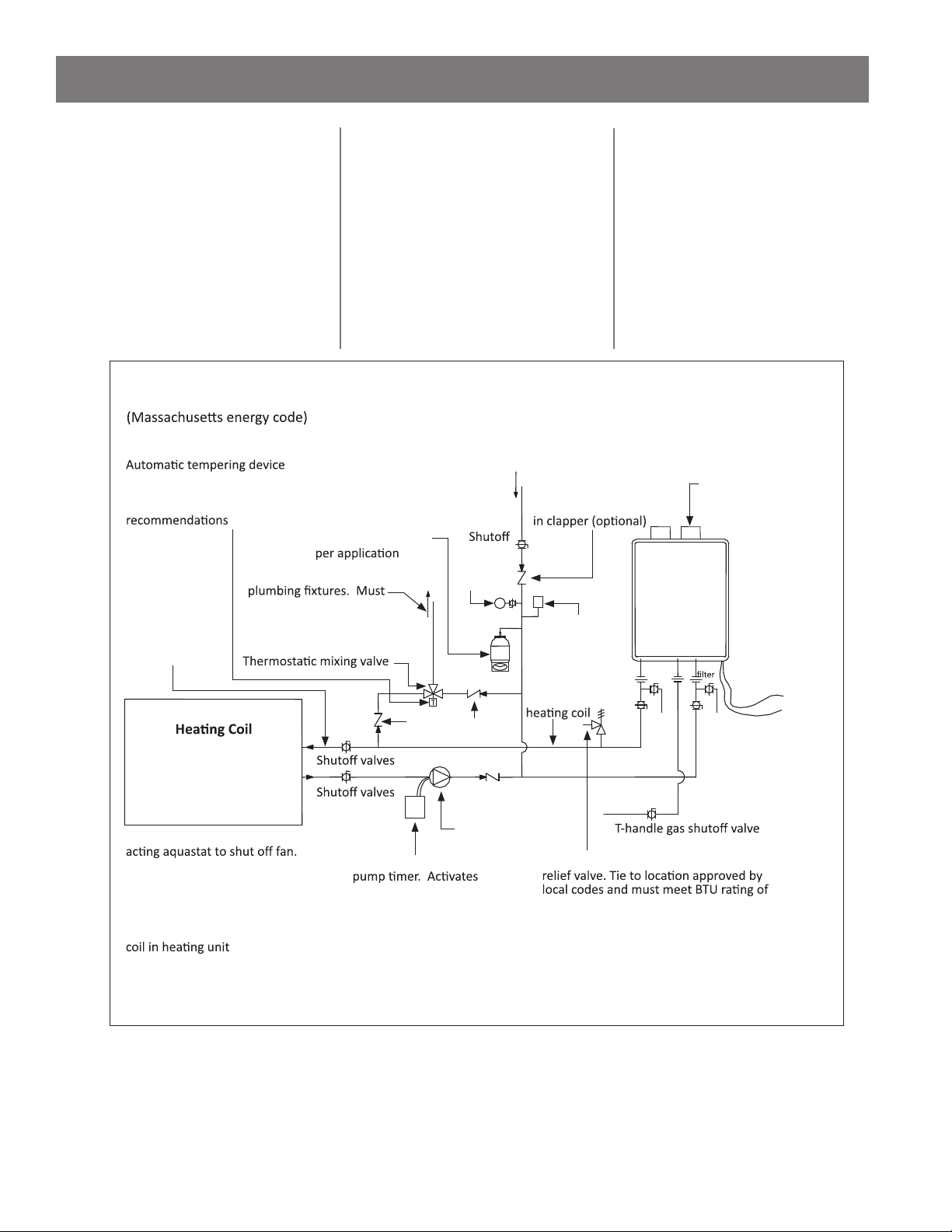
INSTALLATION
Dual Purpose Water
Hea ng for the State
of Massachuse s
• This sec on applicable to
Massachuse s (USA) installa ons
only. Not applicable in Canada.
• Priority Control Devices such as a
fl ow switch, an Aquastat or other
electronic controller can be used
All water piping should be insulated
in accordance with 780 CMR
must be installed below
the top of the water heater
as per manufacturer’s
Piping loop
between water
heater and fan
coil shall be in
compliance with
248 CMR
(used with air-handler)
Tempered water to
meet temperature
requirements of 248 CMR
to priori ze the domes c water
system over the hea ng system.
• Follow all local codes, or in the
absence of local codes, follow the
current edi on of the Na onal
Standard Code, ANSI Z21.10.3, CSA
4.3.
• The illustra on below is a concept
design only. The reference to
the 1/8-inch hole in the check
Apply correct thermal
expansion tank-size
Check valves
valve
Pressure
gauge
Cold water supply
Check valve will have
1/8-inch hole drilling
Atmospheric
vacuum
breaker
Hot water
supply and
return to
Unions
Ball
Val ve
valve is only required in the State
of Massachuse s. There are
a wide variety of varia ons to
the applica on of controls and
equipment presented. Designers
must add all the necessary safety
and auxiliary equipment to
conform to code requirements and
design prac ce. For more details,
contact the manufacturer or local
code authority.
Discharge must
comply with local and
state codes. Cannot
be common vented
with other appliances
Cold water inlet
Gas inlet
Hot water outlet
Drain
plug
Water
IsolaƟŽn
Val ve
120 VAC
switch or
outlet
Check valve
System installed with reverse
Suggested but not required by
248 CMR
50’-0” maximum distance from
water heater to fan coil.
(Developed length) Not including
Electronically controlled
every 6 hours for 60
seconds. Wire to
product approved pump
NSF-61 product
approved pump
An approved temperature and pressure
water heater model used
The ƌĞĐŝƌĐƵůĂƟŽŶ pump is tŽ prŽvide ŶŽ less ƚŚĂŶ 2 GPM (7.5 >ŵŝŶͿ ĂŶĚ ŶŽ ŵŽƌĞ ƚŚĂŶ 4 GPM (15 >ŵŝŶͿ ƚŚƌŽƵŐŚ
each ĂĐƟǀĂted ƵŶŝƚ ŝŶ the system.
Figure 32 - Diagramma c Layout of Radiant Hea ng and Domes c Water Heater
Residen al Gas Tankless Water Heater Use and Care Guide • 39
Page 40
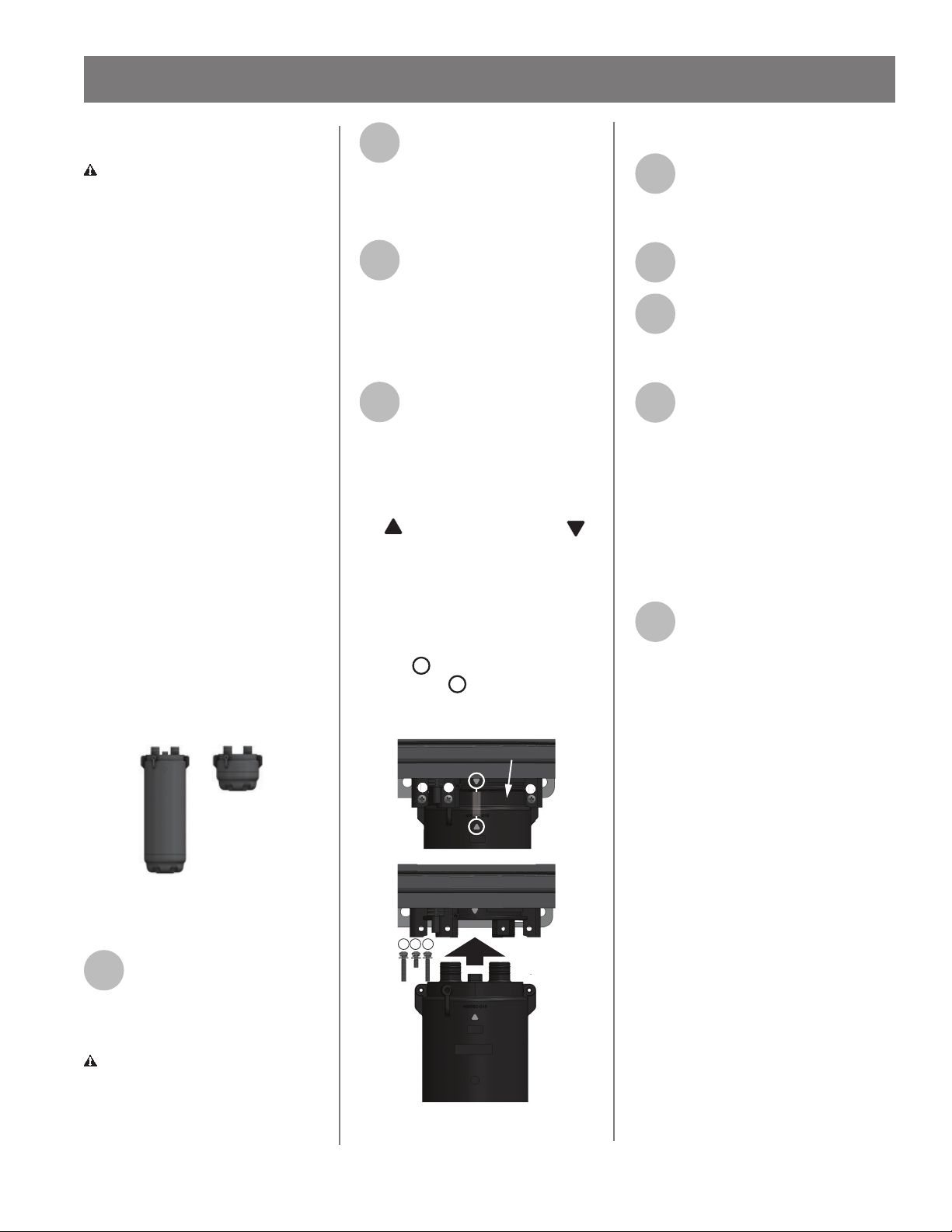
INSTALLATION
A
B
X3® Technology
WARNING! DO NOT operate
water heater un l either the X3®
Cartridge or Bypass cartridge has
been installed into the manifold
located on the underside of the
water heater cabinet. Failure to do
so may result in leaks and poten al
property damage.
This water heater may be equipped
with X3® Scale Preven on
Technology to inhibit scale forma on
within the heat exchanger tubing
of this unit. Part of the X3®
Technology’s an -scale protec on
comes from the special X3®
Cartridge media. The X3® Cartridge
must be installed into the manifold
located on the underside of the
heater cabinet prior to opera on
of the unit (shown as follows). X3®
Scale Preven on Technology reduces
the forma on of scale in the heat
exchanger, extending the opera ng
life of the unit in typical potable
water installa ons. Specifi c water
condi ons may impact the effi ciency
of X3®, such as excessive iron or
manganese levels.
®
X3
Cartridge
Figure 33 - X3® & Bypass Cartridges
X3® Cartridge Installa on
Remove the plug assembly
1
installed into the manifold
located on the underside of
the water heater cabinet. Properly
dispose of plug assembly materials.
CAUTION! Water may be present
in the manifold. Place a bucket
under the water heater cabinet to
collect any residual water.
Bypass
Cartridge
Locate the three (3) screws
2
located in the hardware bag
that is located on the top of
the heater carton. Set the one
M4-12mm screw and two M4-25mm
screws aside in a safe place.
Locate the X3® Cartridge
3
provided with the water
heater.
NOTICE: Inspect o-rings for damage
or debris. Handle with care and
verify lubricant has been properly
applied to o-rings.
Insert the X3® Cartridge into
4
manifold and secure with
the two long screws and
one short screw previously set aside
in Step 2.
NOTICE: The X3® cartridge is keyed
to only install in one direc on. Align
the on the cartridge with the
on the manifold. When inser ng
the cartridge, push up un l the
screw holes align. Some resistance is
normal. See Figure 34.
Insert and snug all three screws by
hand. Use a screwdriver to ghten
the two B screws fi rst and lastly
ghten screw A. DO NOT use a
drill or impact driver to ghten the
screws.
MANIFOLD
AB
ALIGN
A BB
®
X3
CARTRIDGE
Figure 34 - X3® Cartridge Installa on
B
B
X3® Cartridge Removal
Disconnect power to the
1
water heater by unplugging
it or by turning off the
circuit at the breaker box.
Close the cold inlet water
2
valve.
Open all hot water taps in
3
the house. When the
residual water fl ow has
ceased, close all hot water taps.
Remove the two long and
4
one short screws securing
the X3® Cartridge to the
manifold located on the underside of
the water heater cabinet. Set the
screws aside in a safe place for
re-installa on. Place a bucket under
the water heater cabinet to collect
any residual water. Note the order of
the screws when removing them.
Reference Figure 34.
Pull down to remove the
5
X3® Cartridge from the
water heater.
NOTICE: The X3® Cartridge will be
full of water. Use cau on not to lt
the cartridge un l the water has
been drained.
Bypass Cartridge
If the water heater does not use the
X3® Scale Preven on Technology,
confi rm the bypass cartridge has
been properly installed before
opera ng the water heater.
NOTICE: Bypass cartridge installs
the same way as the X3® cartridge,
however it is not keyed.
Pressure Relief Valve
WARNING! Hot water could be
released. Before opera ng the
pressure relief valve manually,
check that it will discharge in a safe
place. If water does not fl ow freely
from the end of the discharge pipe,
turn the gas supply and power
OFF and call a qualifi ed person to
determine the cause.
40 • Residen al Gas Tankless Water Heater Use and Care Guide
Page 41
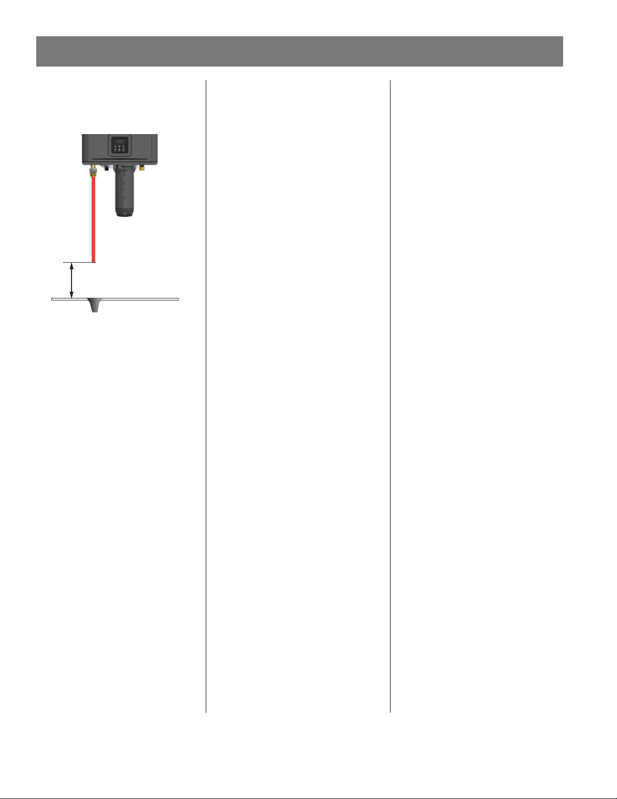
INSTALLATION
Refer to the pressure relief valve
manufacturer's instruc ons for
inspec on and maintenance
requirements.
Discharge Pipe
6” (152.4 mm)
Maximum
Figure 35 - Discharge Pipe
The water heater has a hightemperature shutoff switch built in
as a standard safety feature (called a
Hi-Limit switch) therefore a “pressure
only” relief valve is required.
• An approved pressure relief valve is
supplied with the X3® models. An
approved pressure relief valve shall
be fi eld supplied for the M models.
• The discharge piping for the pressure relief valve must be directed
so that the hot water cannot splash
outward and cause damage or personal injury.
• A ach the discharge tube to the
pressure relief valve and run the end
of the tube to within 6 in (152 mm)
from the fl oor for US installa ons
and 12 in (305 mm) for Canadian installa ons. This discharge tube must
allow free and complete drainage
without any restric ons.
• If the pressure relief valve discharges periodically, this may be due
to thermal expansion in a closed
water supply system. Contact the
water supplier or a local plumbing
professional on how to correct this
situa on. Do not plug the pressure
relief valve.
The pressure relief valve must be
manually operated annually to
check for correct opera on. Before
opera ng the valve manually, check
that it will discharge in a place for
secure disposal.
• No valve must be placed between
the relief valve and the water heater.
• If another pressure relief valve is
used or needs to be replaced, it
must meet the following:
• The pressure relief valve must
conform to local codes.
• The discharge capacity must be
at least 199,000 BTU/h for the
THR-199 model, 180,000 BTU/h
for the THR-180 model,160,000
BTU/h for the THR-160 model,
• The pressure relief valve needs
to be rated for a maximum of
150 psi (1 MPa).
Condensate Drain
• Follow all code requirements of the
local authority on condensate neutralizers and whether or not they are
required for the installa on.
• Discharge condensate (acidic water)
in accordance with all local codes
and common safety prac ces.
• Install minimum 1/2 in corrosion
resistant pipe, such as PVC, for the
condensate drain line. Do not use
metal pipe.
• The condensate drain does not
require a trap.
• Maintain a downward slope on the
drain line(s), including installa ons
in which the drain is not directly
below the water heater.
• If a neutralizer is installed, a fi eld-
supplied overfl ow bypass fi ng
(tee/wye) is recommended.
• Do not connect the condensate
drain line directly to a condensate
pump.
If the drain line is required to have
bends, ensure that there are no
kinks that will restrict the fl ow of
condensa on.
• The condensate drain is at
atmospheric pressure (nonpressurized) and therefore must be
allowed to drain freely with gravity
only. Ensure that the condensate
drain tube is not plugged or blocked,
and ensure that it slopes downward
to allow condensate to fl ow freely.
All por ons of the condensate drain
(neutralizer and drain tube) must be
at a lower eleva on than the water
heater to prevent condensate water
from building up inside the heat
exchanger.
• Condensate cannot be eff ec vely
neutralized if the neutralizer
elements have been completely
consumed. If this happens,
condensate will remain acidic and
can possibly cause damage to items
such as pipes, concrete, etc., if
drained improperly.
• The actual life of the neutralizer may
vary, depending on the applica on
and usage. Replace the cartridge
when the condensate pH goes
below 6.0.
• All preventa ve measures and
safety prac ces must be adhered
to when draining condensate.
The manufacturer will not be
responsible for any damage caused
by condensate.
• A drain pan, or other means of
protec on against water damage, is
recommended to be installed under
the water heater in case of leaks.
Residen al Gas Water Heater Use and Care Guide • 41
Page 42
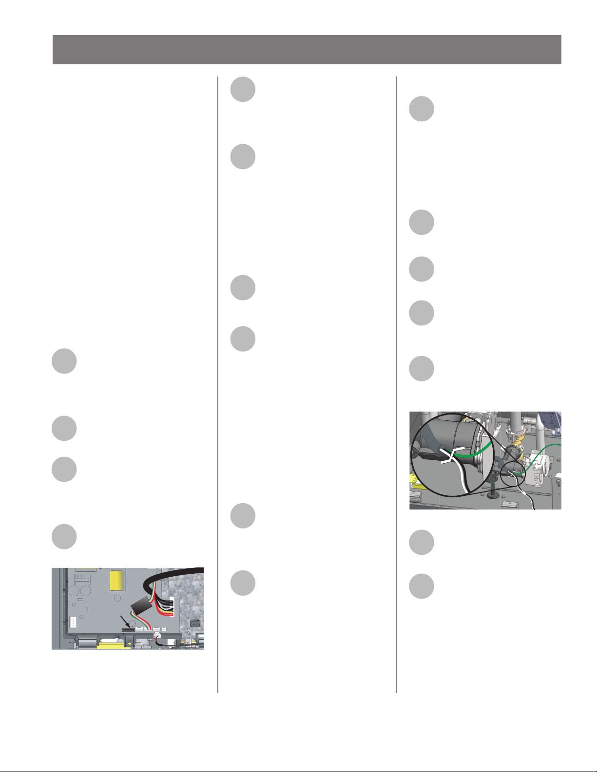
INSTALLATION
Printed Circuit Board
Ba ery
WARNING! Working on an energized
circuit can result in severe injury or
death from electrical shock.
This heater uses a type 2032 ba ery
to store the clock’s me during a
power outage. When the ba ery’s
voltage is low, an error code will
fl ash on the water heater’s display
to indicate the ba ery should be
replaced.
This ba ery only stores the clock’s
me during a power outage. All
other se ngs are saved in the PCB’s
memory.
Follow the instruc ons below to
ac vate the ba ery before the fi rst
use of the water heater.
Ensure the water heater is
1
NOT connected to any
electrical power source. The
unit must NOT have power to perform
the next step.
Remove the front cover.
2
Removed the clear plas c
3
cover over printed circuit
board. Keep this cover for
installa on a er the ba ery is
ac vated.
Locate the “coin” style
4
ba ery slot on the lower part
of the PCB shown in Figure 36
Remove the small tab from
5
the ba ery that is blocking its
connec on. Once the tab is
removed make sure the ba ery is fully
seated in the connector.
A er this step you may
6
proceed to connect the water
heater to electrical power.
NOTE: follow these steps to replace
the ba ery when it is depleted.
Electrical Connec ons
WARNING! Working on an energized
circuit can result in severe injury or
death from electrical shock.
The water heater must be
1
electrically grounded. Do not
attach the ground wire to
either the gas or the water piping.
The water heater requires a
2
120 VAC, 60 Hz electrical
power supply that is properly
grounded.
• A proper disconnect (i.e. on/
off switch, power plug, etc.)
controlling the main power
to the water heater must be
provided for service reasons.
(Must comply with local codes.)
• This water heater comes
equipped with a SJWT rated cord
which is weather resistant and
rated for outdoor use.
The water heater can be
3
hardwired or plugged into an
outlet with the correct voltage
listed above using the supplied power
cable already attached.
Plug-in Connec on
The water heater should be
1
plugged into a 120VAC, 60 HZ
ground electrical outlet.
Hard Wired Connec on
NOTE: Follow the steps below if the
power supply must be hardwired to
the water heater. Otherwise, you may
skip this section.
Remove and keep the screws
1
securing the front cover, then
remove it.
Remove and keep the screw
2
in the upper le corner of the
printed circuit board.
Depress the latch in the
3
upper right corner of the
printed circuit board and
lower it.
Locate the system power cord
4
using Figure 37. Cut the wires
at the loca on shown in
Figure 37.
Figure 37 - System power cord cut loca on.
Remove the screws securing
5
the power cord to the bo om
of the water heater.
The use of a surge protector
4
is recommended in order to
PCB
Battery
Figure 36 - Ba ery loca on on PCB
42 • Residen al Gas Tankless Water Heater Use and Care Guide
surges.
protect the unit from power
Remove the power cord from
6
the bo om of the water
heater and install a strain
relief connector in the opening.
Page 43
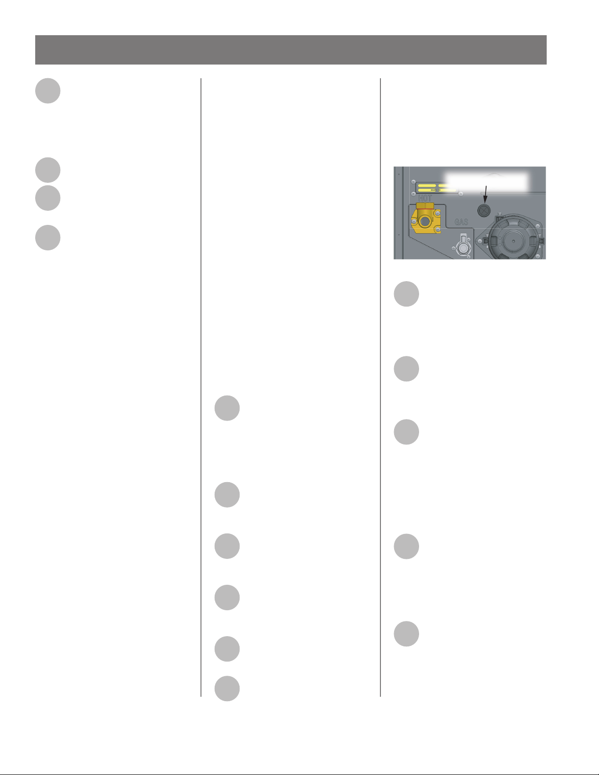
INSTALLATION
Make the electrical
7
connec on to the water
heater. Follow all local codes
or in the absence of local codes, with
the Na onal Electrical Codes: ANSI/
NFPA 70 in the USA.
Verify all electrical
8
connections are secure.
Replace the front cover and
9
turn on power to the water
heater.
10
Follow the instructions in the
Getting Started section of
this manual.
Cascade System
The Cascade System allows up to 12
heaters of the same input to be linked
in a Parent/Child confi gura on. Do not
link heaters of diff erent input rates
together.
The Cascade System will ac vate
heaters based on the system fl ow
rate demand. When system demand
increases or decreases, the cascade
system will ac vate/deac vate
heaters as needed to balance fl ow
through the heaters.
The Parent heater determines when
to ac vate/deac vate heaters. The
order of heater ac va on is set by
the Parent heater and will sequence
the heaters in order from the least
combus on hours to the most. This
allows for even opera on of all the
water heaters in the cascade system.
The heaters will deac vate in the
reverse order that they are ac vated,
meaning if Child Heater 11 was the
last to turn on, it will be the fi rst
to turn off when system demand
decreases. The Parent heater will
reorder the sequence on a weekly
basis.
The new sequence of ac va on
will start with the heater that has
the least combus on hours to the
most. Each heater will ac vate
based on predetermined fl ow rate
factors. These factors vary based
on heater model. Contact the
heater manufacturer for addi onal
informa on.
In a recircula on system, only 1 pump
will operate. The pump in the water
heater sequenced to ac vate fi rst will
operate. The pump opera on will
rotate to the fi rst ac vated heater
during each sequence. The pump
se ngs only need to be set on the
Parent water heater.
If any child heater encounters an error
code, the cascade system will bypass
that heater and con nue to operate.
If the Parent heater loses power, then
the cascade system deac vates. The
user will need to change the se ngs
of one of the other heaters to be the
Parent or resolve the issue of the
Parent heater.
WARNING! Working on an energized
circuit can result in severe injury or
death from electrical shock.
The Cascade system should
1
be configured with the
Parent water heater as either
the first or last in the series of water
heaters connected to the cold water
supply. The Child units will follow
sequentially. See Figure 39.
Before proceeding,
2
disconnect electrical power
to all water heaters in the
Cascade configuration.
Remove the front covers and
3
keep the two screws from
both the Parent and Child
water heaters for re-installation.
On the Parent water heater
4
lift the plastic clip locking the
control panel in place and
lower it down out of the way.
Remove and keep the clear
5
plastic covers over the
Printed Circuit Board (PCB).
On the bo om of the water
6
heater locate the rubber
access grommet. Route the single
harness end of the Cascade Linking
Cable through the bo om and around
to the circuit board.
NOTICE: The cable should be routed
under the circuit board assembly to
prevent strain to the wiring harness.
Rubber Grommet
Figure 38 - Bo om of water heater - Grommet.
Use Figure 39 as a reference
7
to locate the connection
point for the Parent Cascade
Unit. Use the single harness end of
the Cascade Linking Cable to make
the initial connection.
Follow steps 4-6 to route the
8
double harness end of the
Cascade Linking Cable to the
printed circuit board on the first Child
water heater.
If more than one Child water
9
heater is used then route the
single harness end of the
second Cascade Linking Cable through
rubber grommet on the bo om of the
fi rst Child water heater and connect it
to the open harness on the fi rst
Cascade Linking Cable as shown in
Figure 39.
Once all connections are
10
made, the water heaters
must be assigned their
position in the system. Turn on the
power supply to all of the water
heaters, making sure there is no
water flow.
On the Parent water heater
11
simultaneously press and
hold the SETTING and UP
bu ons un l C00 appears. See Table
18 on page 52.
Residen al Gas Tankless Water Heater Use and Care Guide • 43
Page 44
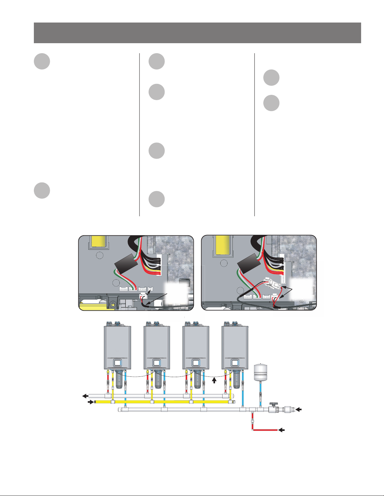
INSTALLATION
t
t
Press the UP arrow button to
12
reach the C13 option, then
press SETTING button to
enter that option.
NOTE: C13 defines the number of
Child water heaters that will be
connected to the parent unit.
Enter the number of Child water
heaters attached to the parent water
heater and press Settings to load the
number to memory. For example, if
the system consists of four total water
heaters, then enter 3 for three child
heaters into C13. Press the SETTING
button again to return to normal
operation.
After the Parent water heater
13
is configured, the Child water
heaters must be configured.
Perform the following steps on each
Child water heater.
Parent Unit
On each Child unit’s UIM,
14
press and hold both the
SETTING and UP buttons until
C00 appears.
Press the UP arrow button to
15
reach the C14 option, then
press the SETTING button to
enter that option.
NOTICE: C14 defines the number
assigned to each Child water heater
connected to the parent water heater.
Enter number 2 for the first
16
Child water heater and press
the SETTING button to load
the number to memory. Repeat this
step assigning a sequencial number at
each additional Child water heater.
Press and hold the SETTING
17
button again to return to
normal operation. NOTICE: A
maximum 11 Child water heaters can
be connected to a Cascade System of
12 total water heaters.
Verify all electrical
18
connections and conduit
connections are secure.
19
Follow the instructions in the
Getting Started section of
this manual.
Child Unit
HWS
Gas
Supply
Parent Unit
Single
Harness
End
Child UnitChild Unit
hild Uni
Figure 39 - Mul Unit Cascade Confi gura on
Child Uni
Cascade
Linking
Cable
Child Unit
Double
Harness
End
CWS
Building Return
44 • Residen al Gas Water Heater Use and Care Guide
Page 45
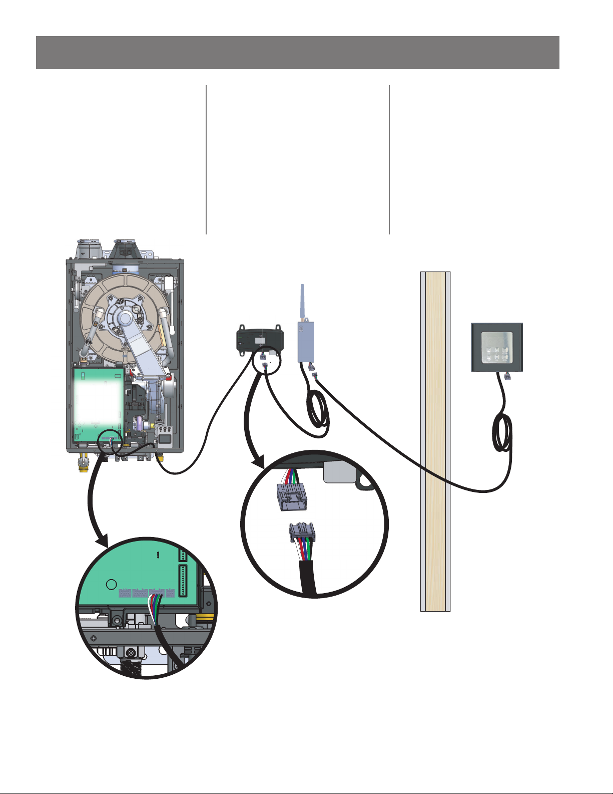
INSTALLATION
Accessory Connec ons
This system supports up to three
accessories connected in series. NOTE:
If mul ple water heaters are used in a
Cascade confi gura on, all accessories
must be connected in series to the
parent unit.
Follow the accessory kit instruc ons
to access the control board.
Each accessory has a both a fi ve pin
female connector and a sec on of
cable with a fi ve pin male connector
on the end. See Figure 40 The male
connector connects to the control
board or to the next accessory in the
series. The fi ve pin female connector
allows another accessory to connect
and create a series. Reference the
fi gure below when crea ng a series
of accessories. If the length of the
accessories cord is not long enough,
Remote
Recirculation
Wi-Fi Module
Receiver
communica on cables can be
purchased to extend the length. These
cables are available in 10
(3 m) and 32 (10 m) lengths.
Connect the single fi ve pin connector
on communica on cable to the
fi ve pin female connector on the
accessory. The maximum wire length
from the water heater (parent in
a Cascade System) to the furthest
accessory is 100 (30 m).
Wall
Remote
Temperature
Controller
Printed
Circuit
Board
Accessory 5
Pin Female
Accessory 5
Pin Male
Figure 40 - Accessories installed in series
Residen al Gas Water Heater Use and Care Guide • 45
Page 46

OPERATION
FOR YOUR SAFETY,
READ BEFORE
OPERATING
WARNING! IF YOU SMELL GAS:
• Do not try to start the water heater.
• Do not touch any electric switches;
do not use any phone in your
building.
• Immediately call your gas supplier
from a neighbor’s phone. Follow the
gas supplier’s instruc ons.
• If you cannot reach your gas
supplier, call the fi re department.
• Failure to observe these warnings
could lead to fi re or an explosion,
resul ng in severe injury or death.
ᅚ Check the GAS and WATER
CONNECTIONS for leaks before
fi ring unit for the fi rst me.
ᅚ Open the main gas supply valve
to the unit using only your hand
to avoid any spark. Never use
tools. If the knob will not turn by
hand, do not try to force it; call
a qualifi ed service technician.
Forced repair may result in a fi re
or explosion due to gas leaks.
ᅚ Be sure to check for the
presence of leaking gas toward
the bo om of the unit because
some gases are heavier than air
and may se le towards the fl oor.
ᅚ Check the GAS PRESSURE. Refer
to “Gas Supply and Gas Pipe
Sizing” on page 33.
ᅚ Check for PROPER VENTING and
COMBUSTIBLE AIR to the water
heater.
replace a fl ooded water heater.
Do not a empt to repair the
unit! It must be replaced!
Start-up Instruc ons
Read and understand these direc ons
thoroughly before a emp ng to
start-up the water heater. Make sure
the water is plumbed correctly before
a emp ng to start the water heater.
Check the data plate on the right side
of the water heater to ensure the
correct gas type. Do not use this water
heater with any gas other than that
for which the heater is confi gured.
If you have any ques ons or doubts,
consult your gas supplier or gas u lity
company.
NOTICE: A newly installed water
heater will have air in the gas line. It
may take several a empts to clear all
the air from the gas line.
Make sure the manual gas
1
valve for the water heater’s
supply line is ON.
Plug the water heater into a
2
grounded 120 VAC outlet or
activate the breaker/
disconnect, if the water heater is
hardwired.
The user interface will display
3
the current temperature set-
ting. The default is 120°F.
To change the set
4
temperature press the “UP”
or “DOWN” buttons to raise
or lower the temperature. See
“Temperature Adjustment/Setting the
Temperature” on page 49.
Shut-Down Instruc ons
Press the “ON/OFF” button
1
and wait for the display to
shut-off.
NOTICE: The power button on the
water heater and remote DOES NOT
disconnect power to the water heater.
You must physically disconnect power
to the water heater.
Emergency Shut-Down
Should overhea ng occur or the gas
supply fail to shut off follow these
steps.
Turn off gas supply to the
1
water heater at the manual
shut-off valve.
Press the “ON/OFF” button
2
on the water heater.
Disconnect power to the
3
water heater by unplugging it
or by turning off the circuit at
the breaker box, as appropriate.
Call a qualifi ed person
4
(licensed plumber, authorized
gas company personnel, or
authorized service technician for
assistance.
ᅚ Purge the GAS and WATER LINES
to remove any air pockets.
ᅚ Do not use this appliance if
any part has been under water.
Immediately contact a qualifi ed
installer or service agency to
46 • Residen al Gas Water Heater Use and Care Guide
Page 47
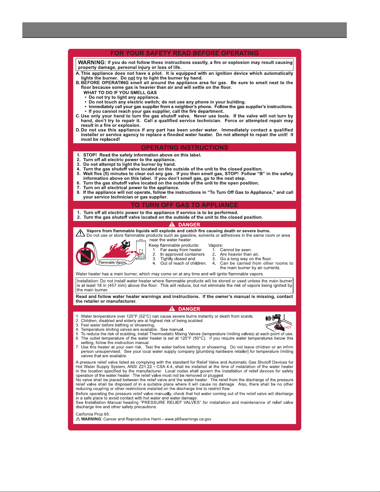
OPERATION
Figure 41 - Ligh ng Instruc ons
Residen al Gas Water Heater Use and Care Guide • 47
Page 48
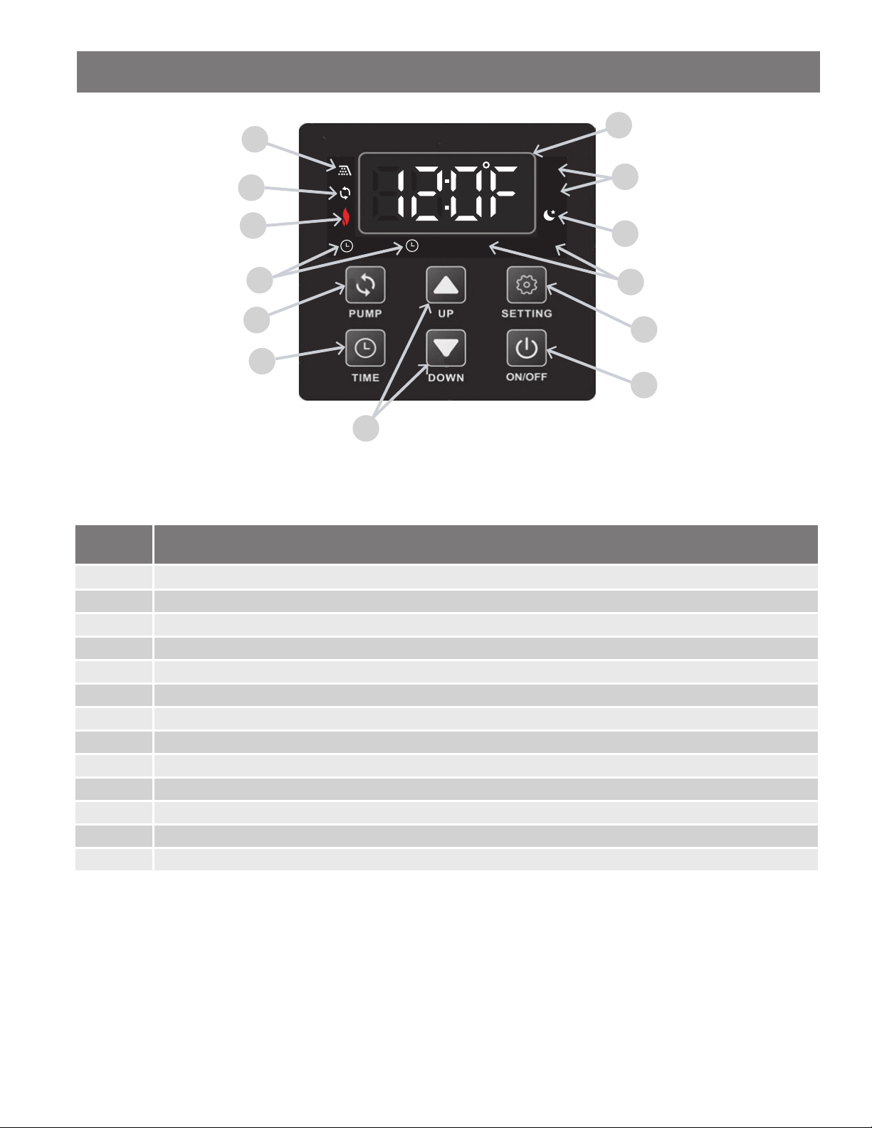
OPERATION
Table 14: User Interface Display
B
C
A
E
D
M
1 2
AM
PM
ON OFF
L
K
J
I
F
H
G
Figure 42 - User Interface Display Diagram
Item Descrip on
A Water Flow Detected
B Pump is Opera ng
C Flame Detected
D Pump Timer 1 & 2 Ac ve
E Pump Bu on
F Time Bu on
G Up & Down Bu ons
H Opera on ON/OFF Bu on
I Se ng Bu on
J Pump Timer ON/OFF Indicators (only shown when se ng the Pump Timers)
K Standby Mode
L AM/PM for Time & Pump Timer Se ng
M Display
48 • Residen al Gas Tankless Water Heater Use and Care Guide
Page 49
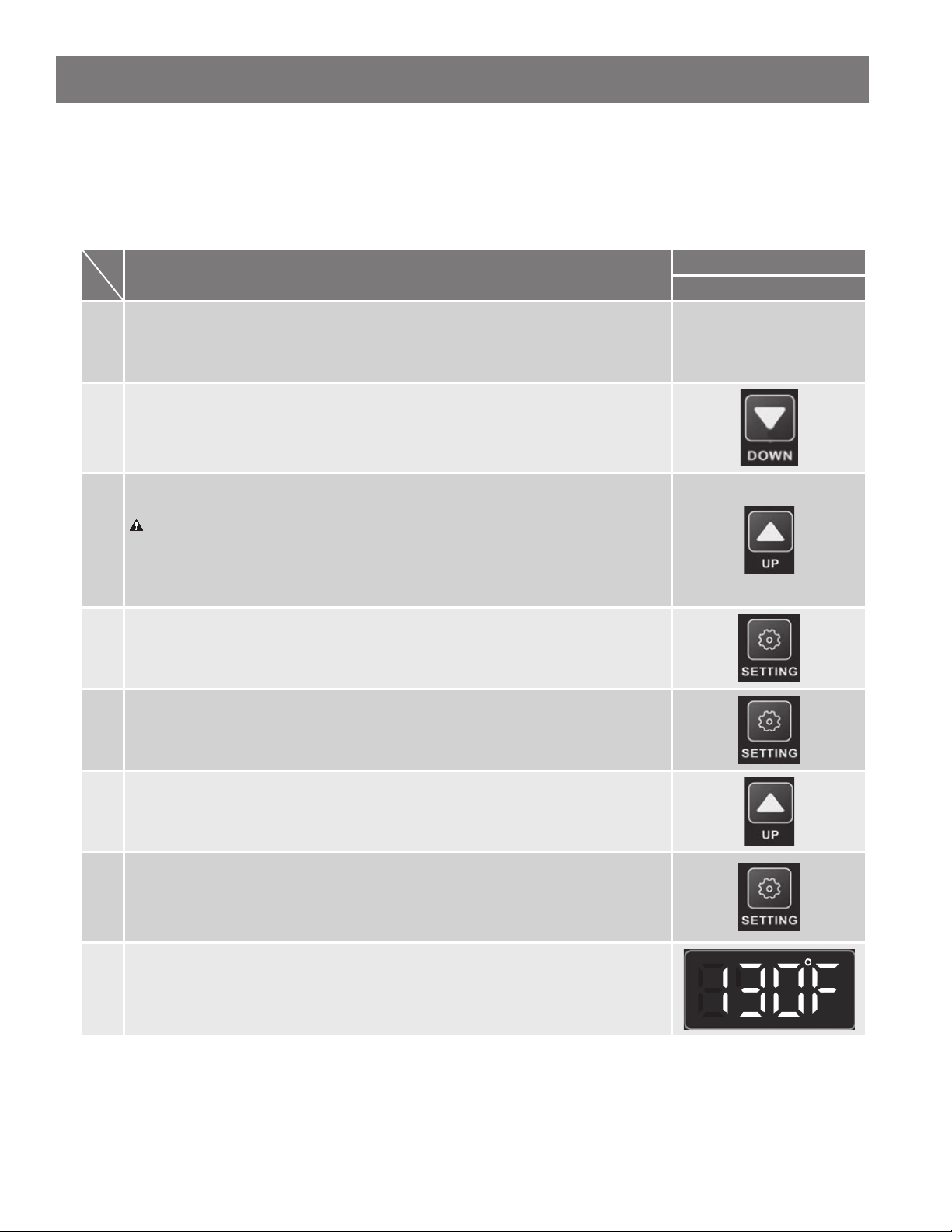
OPERATION
Temperature Adjustment/Se ng the Temperature
With the installa on steps completed, you may adjust the water heater’s temperature se ng if desired. The water
temperature set point is factory set to 120°F (49°C). The temperature set point may be increased or decreased in increments
by simply pressing the “UP” bu on or the “DOWN” bu on. To set the water heater to a temperature above 125°F (52°C),
follow the procedure below.
Opera on
1 Turn on the 120 VAC power supply to the water heater.
2 Press the DOWN bu on to decrease the water temperature.
Press the UP button to increase the water temperature.
WARNING! Higher temperatures increase the risk of scalding, but even at 120 °F
3
(50 °C), hot water can scald (See Table 3).
NOTE: You can only increase the water temperature to 125°F. Addi onal steps are
required to increase the temperature above 125°F.
To raise the temperature above 125°F, press and hold the SETTING button for 5 sec-
4
onds then release. The display will alternately flash A00 and 125°F.
4a Press the SETTING button again. The temperature setting will flash. You can
increase the temperature above 125°F.
Screen on the Controller
Built-in Controller
4b Press the UP button to set the desired temperature.
4c Press and hold the SETTING bu on to return the display to normal opera on. The
new set temperature will appear in the selected unit
(Example: 130°F).
4d The display should show the updated temperature.
Residen al Gas Tankless Water Heater Use and Care Guide • 49
Page 50
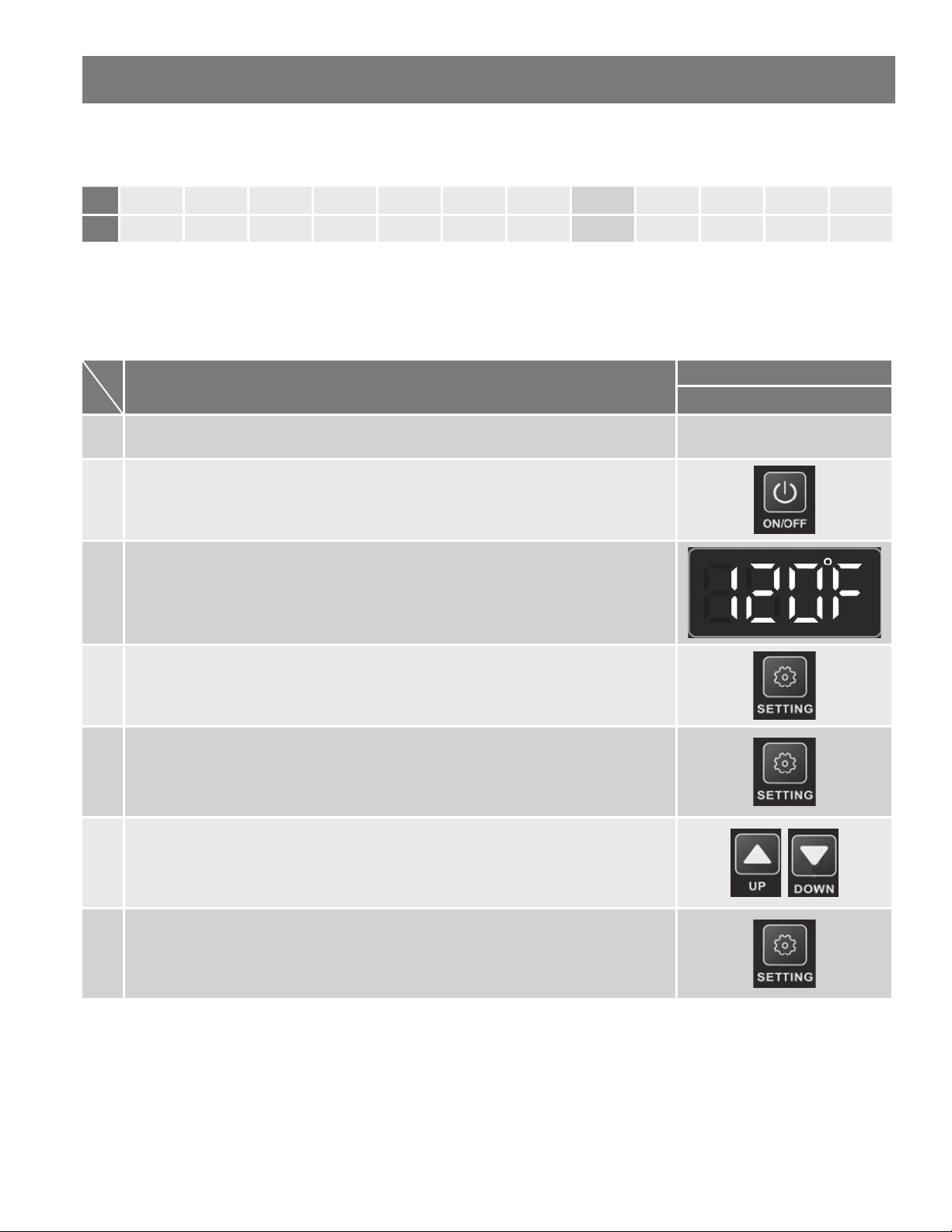
OPERATION
Unit Conversion Mode
Table 15: Water Heater Temperature Set Points
100 102 104 106 108 110 115 120* 125 130 135 140
°F
°C 38 39 40 41 42 43 46 49* 52 54 57 60
Units of measure can be changed from Imperial to Metric and vice versa. For example, temperature can be changed from
°F to °C. Flow rate will also change from gallons per minute to liters per minute when this se ng is changed. Follow this
procedure to change this se ng.
Table 16: Unit Conversion
Opera on
1. Turn on the 120 VAC power supply to the water heater.
2. Press the ON/OFF bu on on the controller in order to turn the controller on.
The set point temperature will display as shown in the picture on the right (Example:
3
120°F).
4 Press and hold the SETTING bu on for 5 seconds to access the water heater A Mode.
The display will show code A00. Press the UP bu on once to display code A01. Press
5
the SETTING bu on to show the current temperature se ng. The temperature will
fl ash.
Screen on the Controller
Built-in Controller
6 Press the UP bu on to alternate between F (Fahrenheit) and C (Celsius).
7 Press the SETTING bu on to execute the change.
50 • Residen al Gas Tankless Water Heater Use and Care Guide
Page 51
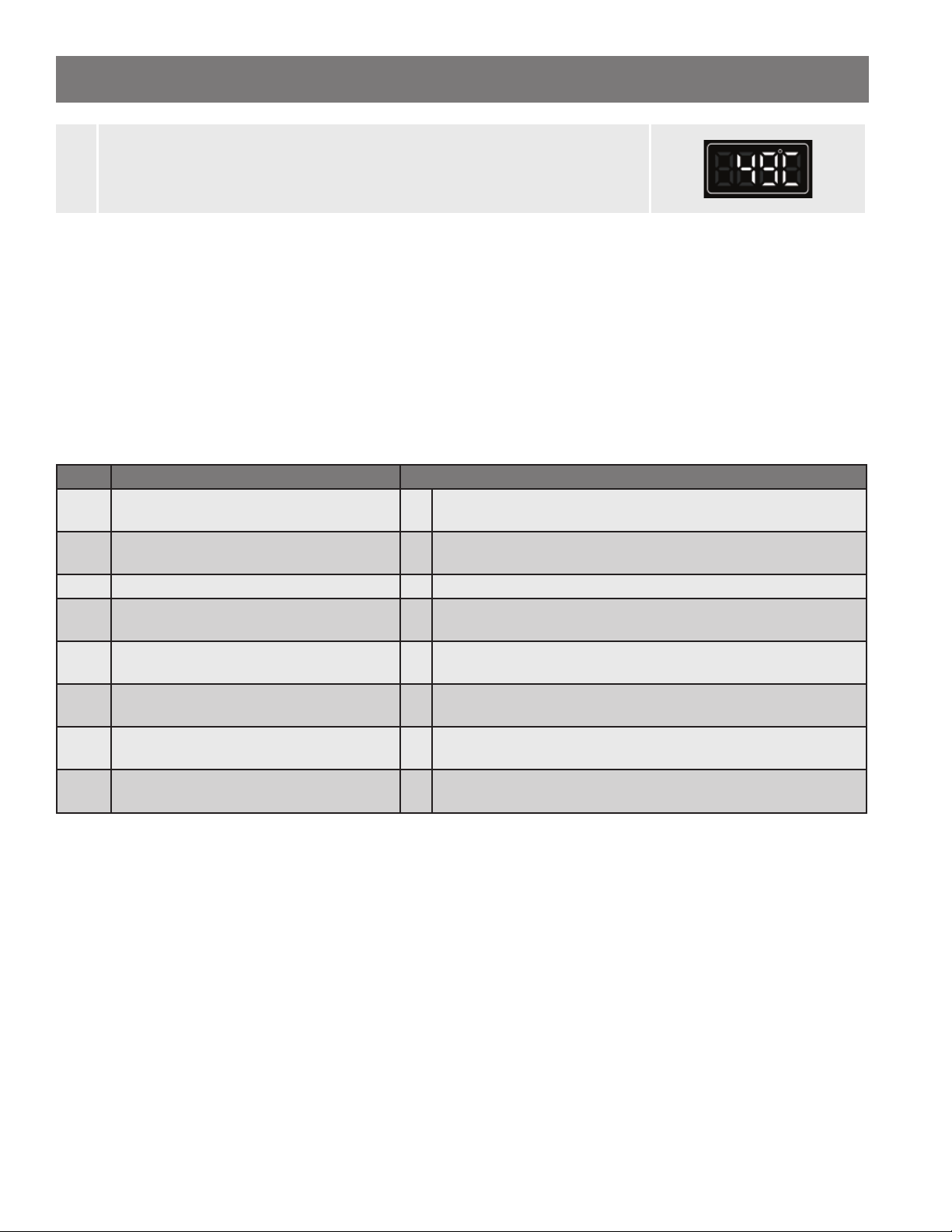
OPERATION
Press and hold the SETTING bu on to return the display to normal opera on. The
8
new set temperature will appear in the selected unit
(Example: 49°C).
Confi gura on Mode (A Mode)
You can confi gure the water heater to accommodate your applica on from A Mode. Follow the procedure below to access A
Mode:
1. Press and hold the SETTING bu on for 5 seconds to access A Mode.
2. Press the UP bu on or the DOWN bu on to search for the desired A Code.
3. If applicable, press the SETTING bu on to adjust the value. When the se ng fl ashes, use the UP or DOWN arrows to change
the se ng.
4. Press the SETTING bu on again to confi rm the new value selected is correct.
5. Press and hold the SETTING bu on for 5 seconds to return the display to normal opera on.
Table 17: A Table Se ngs
CODE DESCRIPTION OPTIONS
A00 Set Temperature Se ng (for High Temp.)
A01 Temperature Unit
°F°C125 130 135 140
52 54 57 60
°F°C°F, °C
A02 Recircula on Interval Timer 5, 10(default), 15, 20, 25, 30, 40, 50, 60 min
A03 Pump Turn On Temperature from Set Point
A04 Pump Turn Off Temperature from Set Point
A05 Recircula on Mode
A06 Recircula on Type
A07 CA Title 24 Mode
°F°C-10 -15 -20 (default) -25 -30 -35 -40
-6 -8 -11 (default) -14 -17 -19 -22
°F°C-5 -10 (default) -15 -20 -25 -30 -35
-3 -6 (default) -8 -11 -14 -17 -19
0:1:No recircula on (default)
Recircula on Ac ve
0:1:Dedicated Return Line (default)
Crossover Valve
0:1:Pump Timer Control (default)
On Demand Control - CA Title 24
Confi gura on Mode (C Mode)
You can confi gure the water heater to accommodate your applica on from C Mode. Follow the procedure below to access C
Mode:
1. Press and hold the “UP” bu on and the “SETTING” bu on for 5 seconds to access C Mode.
2. Press the “UP” bu on or the “DOWN” bu on to search for the desired C Code.
3. If applicable, press the “SETTING” bu on to adjust the value of the C Code using the “UP” and “DOWN” bu ons. The value
will fl ash.
4. Press the “SETTING” bu on again to confi rm the new value selected is correct.
5. Press and hold the “UP” bu on and the “DOWN” bu on for 5 seconds to return the display to normal opera on.
Residen al Gas Tankless Water Heater Use and Care Guide • 51
Page 52
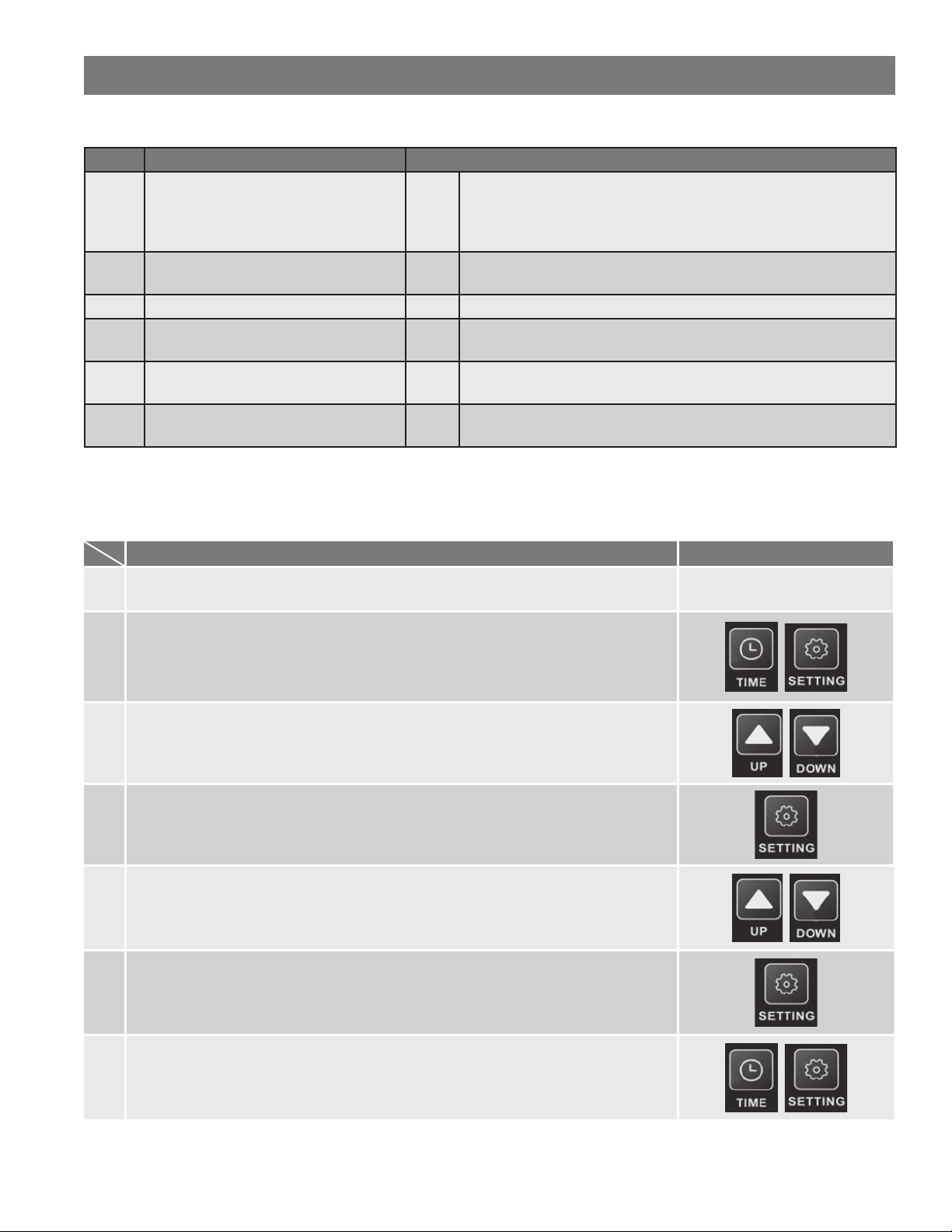
OPERATION
Table 18: C Table Se ngs
CODE DESCRIPTION OPTIONS
0:
0 – 1,999 (default) (0 - 609)
1:
C01 Eleva on Se ngs in Feet (meters)
C03 Gas Type
C07 Power Frequency 60: 60Hz (default)
C13
C14
C15 Descaling Mode
Number of Child Units in
Cascade System
Cascade System Heater ID
Number
1-11:
2-12:
dScL:
Se ng the Clock
Table 19: Clock Se ng
2,000 – 5,399 (610 - 1,645)
2:
5,400 – 7,699 (1,646 - 2,347)
3:
7,700 – 10,100 (2,347 -3,078)
0:1:Natural Gas (default)
Propane
0:
No Cascade System (default)
Iden fy Number of Child Units. This ac vates the Cascade System
1:
Parent Heater (default)
Individually set each child unit per user preference
Off :
No Descale (default)
Ac vate Descale Mode
Set the Time on the Water Heater Built-in Controller
1. Turn on the 120 VAC power supply to the water heater.
Simultaneously Press and Hold the TIME & SETTING bu ons on the front controller
2.
ll the display begins to fl ash.
3. Use the UP or DOWN arrows to set to the current hour.
4. Press the SETTING bu on to confi rm and switch to minutes.
5. Use the UP or DOWN arrows to set the current minute.
6. Press the SETTING bu on to confi rm.
Simultaneously Press and Hold the TIME & SETTING bu ons on the front controller to
7
exit this mode.
52 • Residen al Gas Tankless Water Heater Use and Care Guide
Page 53
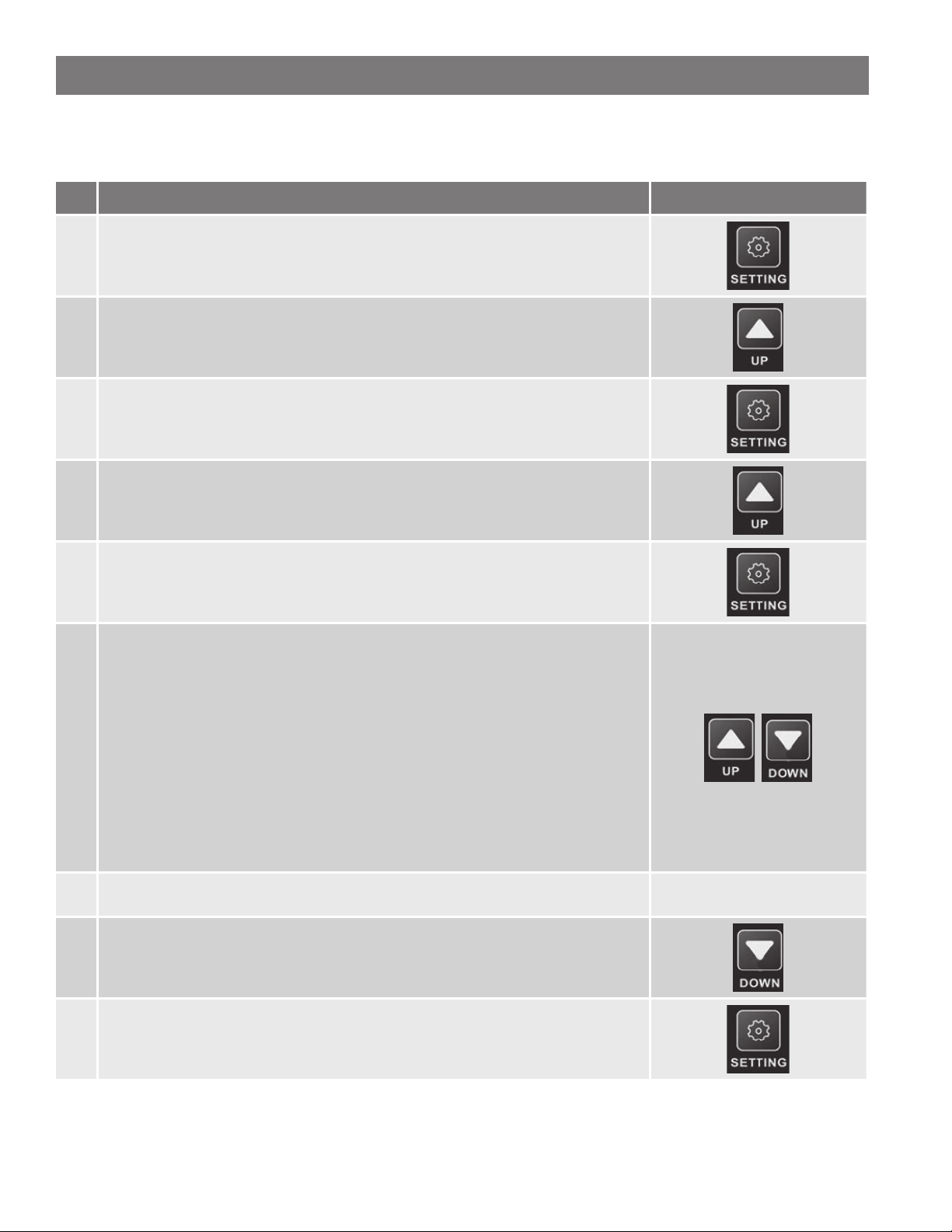
Se ng Recircula on Mode and Recircula on Type
Table 20: Recircula on Mode Se ngs
Ac va ng the Recircula on Modes & Se ng the Aquasta c Parameters Built-in Controller
1 Press and hold the SETTING bu on to enter A mode.
2 Press the UP arrow to mode A05.
3 Press the SETTING bu on. The display will fl ash the current stored se ng.
4 Press the UP arrow to display 1.
OPERATION
Press the SETTING bu on to save the se ng. The display then will alternate between
5
the mode number and se ng.
Press the UP arrow to display A06 and/or A07 based on the recircula on mode and
ac va on/deac va on modes:
a. Set A06 to:
• Press SETTING, then press UP or DOWN to select the desired mode.
• 0 for Recircula on with a Return Line.
• 1 for Recircula on with a Crossover Valve.
6
• Press SETTING to save the selec on.
b. Set A07 to:
• Press the UP arrow to display A07
• Press SETTING, then press UP or DOWN to select the desired mode.
• 0 to ac vate the pump with the Pump Timers. Go to step 7.
• 1 to ac vate the pump with the On-Demand Push Bu on.
• Press SETTING to save the selec on. Go to step 19.
Steps 7-10 sets the standby me from the previous heater opera on, in minutes, ll
the next pump ac va on.
7 Press the DOWN bu on to go to mode A02.
Press the SETTING bu on to change the me delay se ng. Refer to Table 17 on page
8
51 for available mes.
Residen al Gas Water Heater Use and Care Guide • 53
Page 54
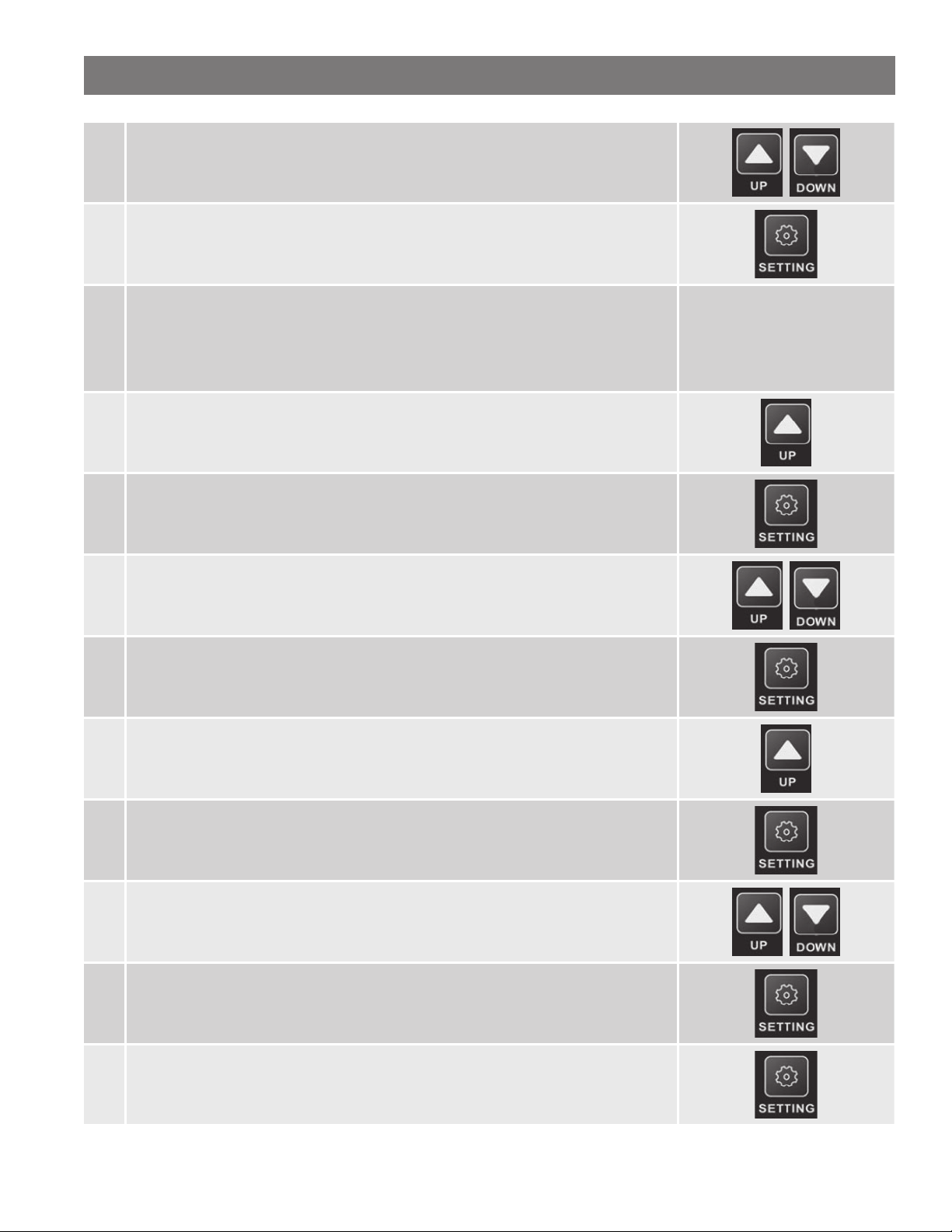
OPERATION
9 Press the UP or DOWN bu on to scroll to the desired me delay.
Press the SETTING bu on to save the se ng.
10
Go to the next step if the se ng in A06 is 0 (recircula on with a return line).
Go to step 19 if the se ng in A06 is 1 (crossover valve recircula on).
Steps 11-18 sets the inlet water temperatures to ac vate/deac vate the pump. These
values are subtracted from the water heater’s set temperature.
For example, with the default A03/A04 se ngs and set temperature of 120°F (49°C),
the pump will ac vate when the inlet water temperature goes below 100°F (38°C)
and deac vate when the inlet water temperature goes above 110°F (43°C).
11 Press the UP bu on to go to mode A03.
Press the SETTING bu on. The display will alternate between the mode number and
12
the current se ng.
Press the UP or DOWN bu on to select the desired se ng. Refer to Table 17 for
13
available se ngs.
14 Press the SETTING bu on to save the se ng.
15 Press the UP bu on to go to mode A04.
Press the SETTING bu on. The display will alternate between the mode number and
16
the current se ng.
Press the UP or DOWN bu on to select the desired se ng. Refer to Table 17 for
17
available se ngs.
18 Press the SETTING bu on to save the se ng.
Press and hold the SETTING bu on to exit the A mode. The display will return to the
19
set temperature.
54 • Residen al Gas Tankless Water Heater Use and Care Guide
Page 55
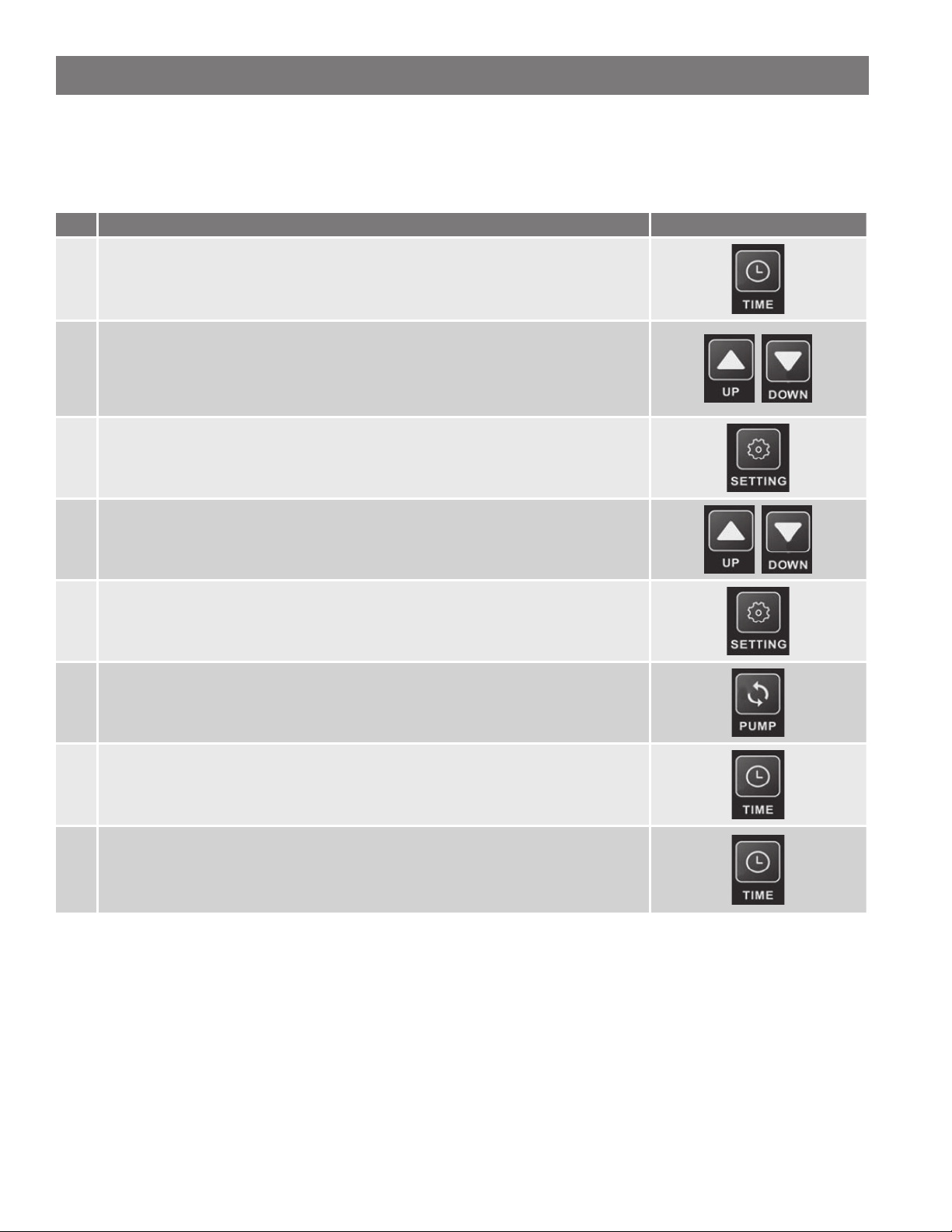
Se ng the Pump Timers
Table 21: Se ng the pump mers
Se ng the Pump Timers Built-in Controller
Press and hold the TIME bu on. The display will fl ash the hour value for Pump Timer
1
1. The Pump Timer 1 symbol and ON will be displayed.
2 Press the UP or DOWN arrow to change the hour to the desired ac va on me.
3 Press the SETTING bu on to save the se ng and adjust the minute.
Press the UP or DOWN arrow to adjust minute. The ON se ng for Pump Timer 1
4
should now be set.
MAINTENANCE
5 Press the SETTING bu on to save the se ng.
Press the PUMP bu on to switch to the OFF me for Pump Timer 1. The Pump Timer
6
1 symbol and OFF will be displayed below the me. Repeat steps 2-5 to set the off
me for Pump Timer 1.
Press the TIME bu on to switch to Pump Timer 2 and repeat steps 2-5 to set the ON
7
and OFF mes.
8 Press and hold the TIME bu on to exit.
Residen al Gas Water Heater Use and Care Guide • 55
Page 56
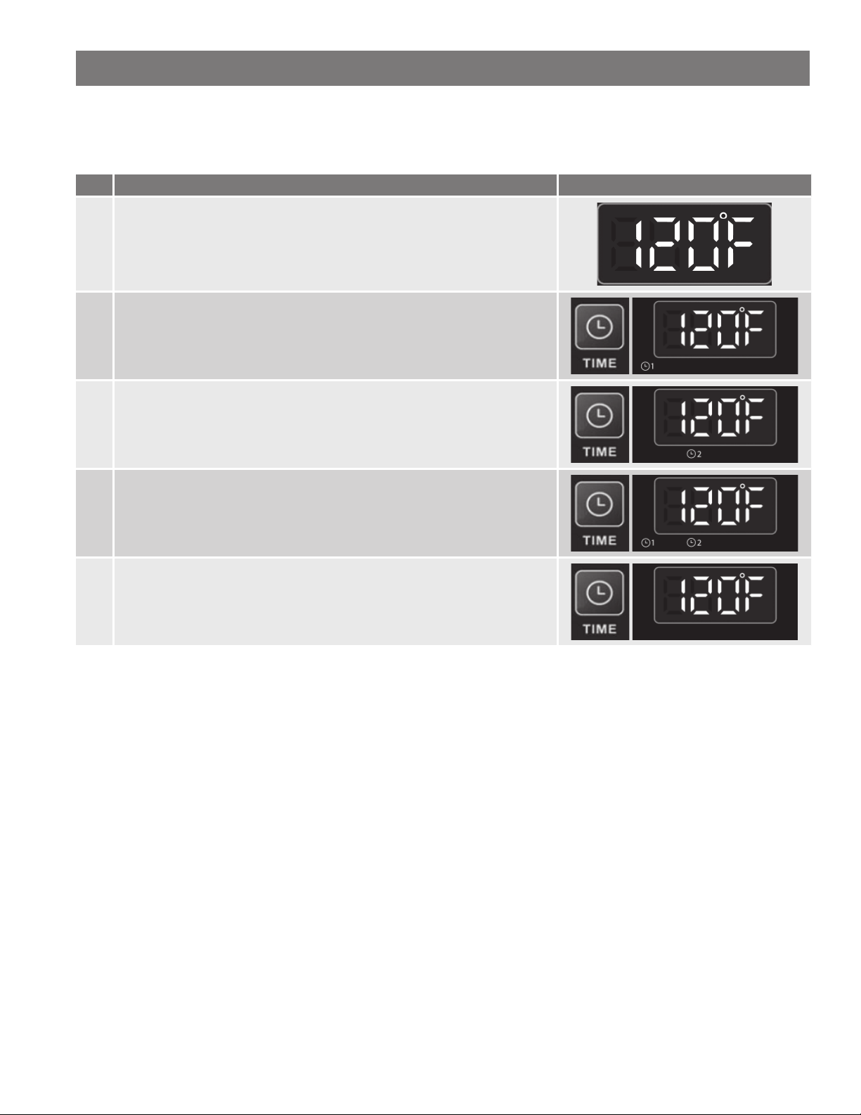
MAINTENANCE
Pump Timer Ac va on
Table 22: Pump Timer Ac va on
Ac va ng the Pump Timers Built-in Controller
1 Display must be showing the set temperature.
Press and release the TIME bu on. The Pump Timer 1 LED will display a er
2
approximately 1 second. This will indicate that Pump Timer 1 is ac vated
3 Press and release the TIME bu on to ac vate only Pump Timer 2.
4 Press and release the TIME bu on to ac vate both Pump Timers.
5 Press and release the TIME bu on to turn off both Pump Timers.
56 • Residen al Gas Tankless Water Heater Use and Care Guide 56 • Residen al Gas Tankless Water Heater Use and Care Guide
Page 57
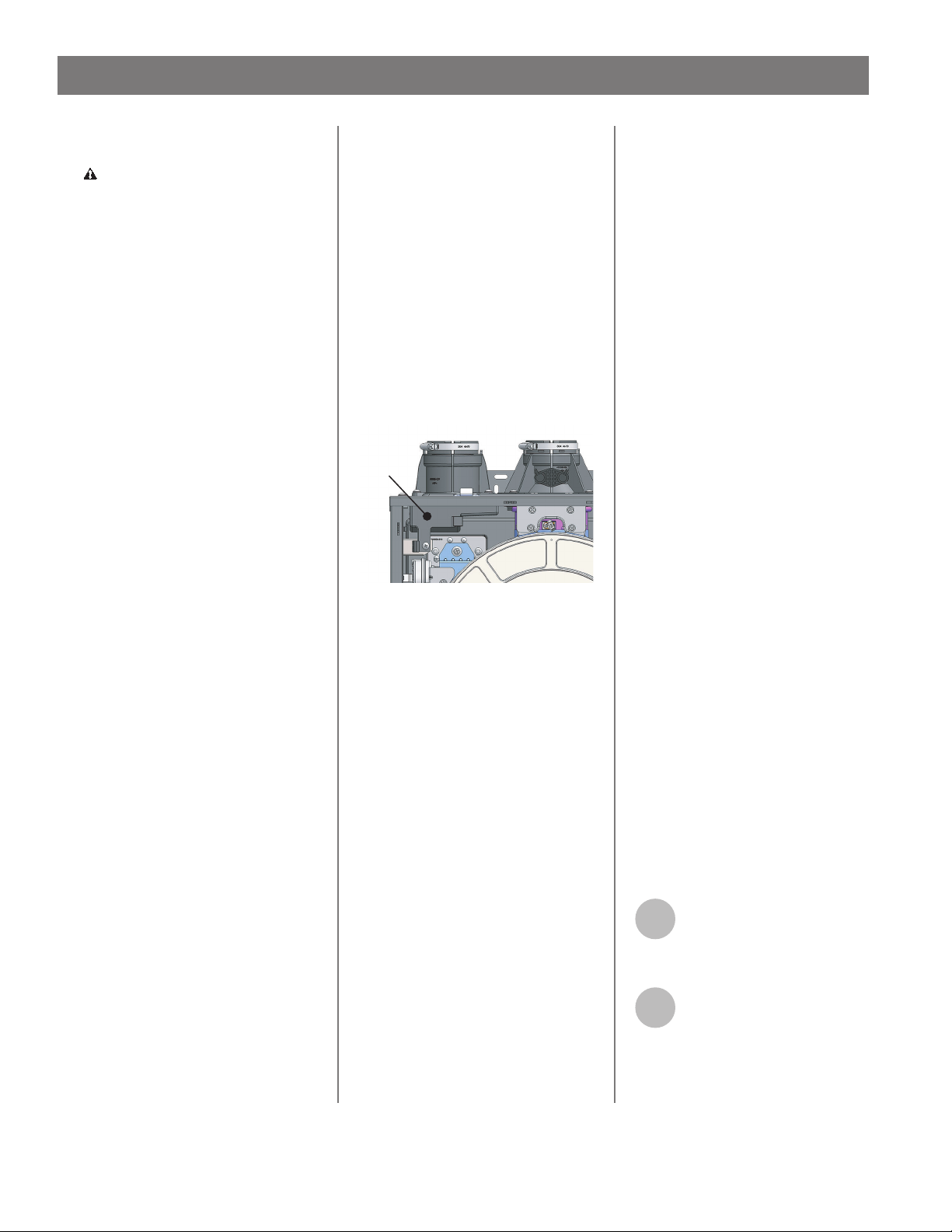
MAINTENANCE
Regular Maintenance
WARNING! Turn OFF the
electrical power supply and close
the manual gas shut-off valve and
the manual water control valve
before servicing. Failure to do so
could result in serious personal
injury or death.
Rou ne maintenance will help your
water heater last longer and work
be er. Failure to perform required
or recommended maintenance may
void the warranty. If you cannot
perform these rou ne maintenance
tasks yourself, contact a qualifi ed
person:
The manufacturer recommends
having the unit checked once a
year or as necessary by a licensed
technician or qualifi ed person. If
repairs are needed, any repairs
should be done by a licensed
technician.
• Clean the cold-water/inlet fi lter.
• The intake and ven ng system
should be checked annually for
any leaks, corrosion, blockages,
or damage. Replace any damaged
sec on of ven ng and clear any
blockage.
• Keep the area around the water
heater and termina ons clear. Reg-
ularly ensure that the area around
the water heater, vent termina on,
and air intake is free from dust,
debris, and other contaminants.
Remove any combus ble materi-
als, gasoline, fl ammable vapors,
and liquids.
• If the pressure relief valve dis-
charges periodically, it may be due
to thermal expansion in a closed
water supply system. Contact the
water supplier or local plumbing
inspector on how to correct this
situa on.
• The pressure relief valve must be
manually operated annually to
check for correct opera on. Before
opera ng the valve manually,
check that it will discharge in a
place for secure disposal.
• The condensate drain system
must be inspected regularly that it
drains properly in accordance with
local codes or the manufacturer’s
instruc ons.
• The screen on the rain protec on
tray should be inspected annually
and cleaned if needed.
Rain
Protection
Tray
Figure 43 - Rain Protec on tray
Freeze Protec on System
This unit comes equipped with
hea ng blocks as well as the auto-
fi re mode to protect it from damage
associated with freezing. The autofi re mode ac vates the burner for a
short period of me.
For this freeze protec on system to
operate, there has to be electrical
power to the unit. Damage to the
heat exchanger caused by freezing
temperatures due to power loss is
not covered under the warranty. In
cases where power losses can occur,
consider the use of a backup power
supply.
It is the installer’s responsibility
to be aware of freezing issues and
take all preventa ve measures. The
manufacturer will not be responsible
for any damage to the heat
exchanger as a result of freezing.
NOTICE: Only pipes within the
water heater are protected by the
freeze protec on system. Any water
pipes (hot or cold) located outside
the unit will not be protected.
Properly protect and insulate these
pipes from freezing. See “Available
Accessories” on page 15 for the
Cartridge Freeze Protec on Kit.
This kit is availble for both the X3®
Models and M Models.
If you will not be using your heater
for a long period of me or power
has been lost during freezing
condi ons:
Completely drain the water
1
out of the unit (see “Unit
Draining & Power Outage
(Freeze Protec on)” on page 58.
Disconnect power to your
2
water heater.
Residen al Gas Water Heater Use and Care Guide • 57
Page 58

TROUBLESHOOTING
Unit Draining & Power
Outage
(Freeze Protec on)
1. Close the manual gas shutoff
valve.
2. Disconnect power to the water heater by unplugging it or
by turning off the circuit at the
breaker box.
3. Close the cold inlet water valve.
4. Open all hot water taps in the
house. When the residual water
fl ow has ceased, close all hot
water taps.
5. Drain the X3® (or Bypass)
Cartridge: Have a bucket or pan
to catch water from the X3®
Cartridge. To remove the X3®
Cartridge, remove and keep the
3 screws securing the cartridge
in place. Pull down to remove it
from the water heater. Empty the
water out of the cartridge into
the bucket.
6. Wait a few minutes to ensure all
water has completely drained
from the unit.
7. Keep the cold water valve closed.
Keep the gas valve closed. Keep
supply power disconnected.
8. To restore the unit to opera on
reinstall the X3® Cartridge with 3
screws removed earlier.
9. Open the cold inlet water valve.
Check all water connec ons for
leaks. If leaks are found, shut-off
the cold water inlet valve and
immediately fi x any leaks. If no
leaks are present proceed to the
next step.
10. Reconnect power to the water
heater.
11. Open the manual gas shutoff to
the water heater.
12. If the set temperature is not
displayed, press the ON/OFF
bu on.
13. NOTE: If any errors occur shutoff
the water immediately.
Condensate Drain
• Inspect the drain lines for any clogs
and clear.
• Check the drain lines for a down-
ward slope. Correct any lines where
water does not drain freely.
• Inspect the built-in condensate trap
drain lines for debris. Disconnect the
lines and drain to remove the debris.
• If a neutralizer is installed, check the
pH. Replace the neutralizer if the pH
of the outlet water is below 6.0.
• If this fi lter is clogged, water will
not be supplied to the water heater
properly.
Inlet Water Filter
1. Close the manual gas shutoff
valve.
2. Disconnect power to the water heater by unplugging it or
by turning off the circuit at the
breaker box.
3. Close the inlet water valve.
4. Open all hot water taps in the
house. When the residual water
fl ow has ceased, close all hot
water taps.
5. Drain the X3® (or Bypass)
Cartridge: Have a bucket or pan
to catch water from the X3®
Cartridge. To remove the X3®
Cartridge, remove and keep the
3 screws securing the cartridge
in place. Pull down to remove
it from the water heater. Empty
the water out of the cartridge
into the bucket. For detailed
instruc ons see “X3® Cartridge
Removal” on page 40.
6. Wait a few minutes to ensure all
water has completely drained
from the unit.
7. Unscrew the inlet water fi lter and
remove it from the water heater.
8. Clean the fi lter: Check the water
fi lter located within the cold inlet.
With a ny brush, clean the water
fi lter of any debris which may
have accumulated.
9. Screw the inlet water fi lter back
into place. Hand- ghten only.
NOTICE: Handle with care and
verify the O-ring is not dirty or
damaged.
10. To restore the unit to opera on
reinstall the X3® Cartridge with
3 screws removed earlier. For
detailed instruc ons see “X3®
Cartridge Installa on” on page
40.
11. Turn ON the cold water supply
to the water heater at the cold
inlet valve. The system will fully
pressurize and any leaks at water
connec ons will be apparent.
Correct any leaks immediately.
12. Turn ON the gas supply to the
water heater at the manual gas
shut off valve.
13. Restore power to the water
heater. The water heater is now
ready for opera on.
58 • Residen al Gas Water Heater Use and Care Guide
Page 59

General Troubleshoo ng
Table 23: Troubleshoo ng Chart
PROBLEM SOLUTIONS
It takes a long me to
get hot water at the
fi xtures.
The water is not hot
enough.
The water is too hot. • Is the set temperature set too high?
The hot water is not
available when a
fi xture is opened.
Temperature and Amount of Hot Water
The hot water turns
cold and stays cold.
Fluctua on in hot
water temperature.
Unit does not ignite
when water goes
through the unit.
The fan motor is
s ll spinning a er
WATER HEATER
opera on has
stopped.
Unit sounds abnormal
while in opera on
• The me it takes to deliver hot water from the water heater to your fi xtures depends on the
length of piping between the two. The longer the distance or the bigger the pipes, the longer it
will take to get hot water.
• If using the recircula on pump, check the se ngs to verify the Pump Timers are ac ve.
• Check the set temperature of the water heater and adjust, if necessary.
• Check cross plumbing between the cold water lines and hot water lines.
• Is the gas supply valve open fully?
• Is the gas line sized properly?
• Is the gas supply pressure suffi cient?
• Check if the Point-of-Use mixing valves are set correctly, if they are installed.
• Make sure the unit has 120 VAC, 60 Hz power supply and power frequency is set to 60 hz.
• Verify the opera on se ng is ON by viewing the UIM. If the set temperature is showing or
you press the UP arrow to display the set temperature, then the opera on se ng is ON. If the
display is blank and nothing appears when pressing the UP bu on, then the opera on state
is set to OFF. Press the ON/OFF bu on to ac vate the heater. The set temperature will display
when set to ON.
• Is the gas supply valve open fully and within the allowable gas pressure range?
• Is the water supply valve open fully?
• Is the fi lter on the cold water inlet clean?
• Is the hot water fi xture suffi ciently open to draw at least 0.4 GPM
(1.5 L/min) through the water heater?
• Is the unit frozen?
• Is there enough gas in the tank / cylinder? (For Propane models)
• Is the fl ow rate enough to keep the water heater running?
• If there is a recircula on system installed, does the recircula on line have
enough check valves?
• Is the gas supply valve open fully?
• Is the fi lter on the cold water inlet clean?
• Are the fi xtures clean of debris and obstruc ons?
• Is the fi lter on the cold water inlet clean?
• Is the gas line sized properly?
• Is the supply gas pressure suffi cient?
• Check for cross connec on between the cold water lines and hot water lines.
• Is the fl ow rate over 0.4 GPM (1.5 L/min)?
• Check for the fi lter on the cold water inlet.
• Check for reverse connec on and cross connec on.
• If you use the remote controller and/or built-in controller, is the power bu on
turned on?
• Check if the inlet temperature is too high. If it is too close to the set temperature,
the water heater will not ac vate.
• This is normal. A er opera on has stopped, the fan motor keeps running
in order to re-ignite quickly, as well as purge all the
exhaust gas out of the fl ue.
• Contact Technical Support Department.
TROUBLESHOOTING
Residen al Gas Water Heater Use and Care Guide • 59
Page 60

TROUBLESHOOTING
Error Codes
The water heater has self-diagnos c func ons for safety and convenience when troubleshoo ng.
If there is a problem with the installa on or the unit, the error code associated with that failure will be displayed on the built-in
controller or remote controller. The display will fl ash E and the three digit number. It will show leading zeros. Example: E002
Error codes in the cascade system are diff erent. The heater number and E### (three digit number) will alternately fl ash on the
parent unit’s user interface module (UIM) and temperature remote controller. The child unit in error will fl ash the E### (three
digit number) on it’s UIM.
Consult the the table below for the descrip on of each error code.
Fault Analysis of Error Codes
If the water heater is displaying an error code, please check the following. A er checking, consult with the manufacturer.
Table 24: Error Code Fault Analysis
Error
Code
E002 Hi-Limit Switches
E006 PCB Hardware Fault
E010 Frequency Fault
E011 PCB - Memory
Error Type Procedure
1. Manual Hi-Limit Switch on water outlet tripped. Check the switch for proper
opera on. Press the reset bu on (center of the switch), to reset it. NOTE: You
will hear and feel the switch click when rese ng it.
If the high limit switch con nues to trip contact a qualifi ed service technician.
2. Automa c Hi-Limit Switch on burner door tripped. If the automa c Hi-limit
switch trip has occurred, it cannot be reset and must be replaced. Contact a
qualifi ed service technician.
1. Check PCB wiring for loose, damaged, or cut wires/connectors. Correct any loose
connec ons and replace any damaged wires/connectors. If all wires/connectors
are intact, replace the PCB.
1. PCB has detected an incorrect power supply frequency. Note the default frequency is 60 Hz. Confi rm that C07 is set to the correct frequency of the supply
power. See Table 18 to access modes
2. If the se ng is correct and the error s ll occurs contact a qualifi ed service
technician.
1. The water heater will con nue to operate while in this error code is fl ashing,
however, the recircula on pump will be disabled. If this heater is part of a cas-
cade system, then the system will be aff ected based on the heater’s se ng.
• Parent Heater: The cascade system will not operate. Remove this heater from
the cascade system and set a diff erent heater as the Parent.
• Child Heater: This heater will not operate. The rest of the cascade system will
con nue to run.
WARNING! Working on an energized circuit can result in severe injury or death from
electrical shock.
E036 Flame Failure
60 • Residen al Gas Water Heater Use and Care Guide
1. Check the fl ame sensor wire for a short or disconnec on. Correct any loose
connec ons and replace any damaged wire/connector. If the error s ll occurs,
contact a qualifi ed service technician.
Page 61
TROUBLESHOOTING
Error
Code
E037 False Flame Detec on
E038 Igni on Failure
E041 Outlet Water Over-temp.
E045 Clock Ba ery Replacement
Error Type Procedure
WARNING! Working on an energized circuit can result in severe injury or death from
electrical shock.
1. Check for a visible fl ame through the sight glass while water is not running
through the water heater. If the error s ll occurs, immediately shut-off the water
heater and contact a qualifi ed service technician.
2. Check the fl ame sensor wire for a short or disconnec on. Correct any loose con-
nec on and replace any damaged wire/connector. If the error s ll occurs, contact
a qualifi ed service technician.
WARNING! Working on an energized circuit can result in severe injury or death from
electrical shock.
1. Check for a visible fl ame through the sight glass.
2. Check the fl ame sensor wire and igniter wire for a short or disconnec on. Cor-
rect any loose connec ons and replace any damaged wire/connector. If the error
s ll occurs, contact a qualifi ed service technician.
1. Verify the thermistor reading with the water outlet temperature.
2. Remove the outlet thermistor (do not lose the o-ring) and check for any dirt or
debris. Clean with an Emery cloth. If the thermistor is damaged, replace it. If the
error s ll occurs, contact a qualifi ed service technician.
1. The clock ba ery voltage is low indica ng it should be replaced with a 2032 type
ba ery. This error may also appear when supply power has been turned back on.
In this case, ignore the error code. Reference “Printed Circuit Board Ba ery” on
page 42. Note: The ba ery has a plas c cover, remove before installa on.40
E049 Exhaust Thermistor Failure
E050 Inlet Thermistor Failure
E051 Outlet Thermistor Failure
E052
Heat Exchanger Thermistor
Failure
1. Remove the thermistor (do not lose the o-ring) and check for any dirt or debris.
Clean with an Emery cloth. If the thermistor is damaged, replace it.
2. Check the Thermistor sensor wire for a short or disconnec on. Correct any loose
connec ons and replace any damaged wire/connector. If the error s ll occurs,
contact a qualifi ed service technician.
1. Remove the thermistor (do not lose the o-ring) and check for any dirt or debris.
Clean with an Emery cloth. If the thermistor is damaged, replace it.
2. Check the Thermistor sensor wire for a short or disconnec on. Correct any loose
connec ons and replace any damaged wire/connector. If the error s ll occurs,
contact a qualifi ed service technician.
1. Remove the thermistor (do not lose the o-ring) and check for any dirt or debris
clean with Emery cloth. If the thermistor is damaged, replace it.
2. Check the Thermistor sensor wire for a short or disconnec on. Correct any loose
connec ons and replace any damaged wire/connector. If the error s ll occurs,
contact a qualifi ed service technician.
1. Remove the thermistor (do not lose the o-ring) and check for any dirt or debris
clean with Emery cloth. If the thermistor is damaged, replace it.
2. Check the Thermistor sensor wire for a short or disconnec on. Correct any loose
connec ons and replace any damaged wire/connector. If the error s ll occurs,
contact a qualifi ed service technician.
Residen al Gas Water Heater Use and Care Guide • 61
Page 62
TROUBLESHOOTING
Error
Code
E383 Inlet Water Over-Temp.
E384 False Flame Detec on
E385 Gas Valve - SV1
Error Type Procedure
1. Verify the inlet water temperature is not above the water heater’s set temperature.
2. Remove the inlet thermistor (do not lose the o-ring) and check for any dirt or
debris. Clean with Emery cloth. If the thermistor is damaged, replace it.
3. Check the Thermistor sensor wire for a short or disconnec on. Correct any loose
connec ons and replace any damaged wire/connector. If the error s ll occurs.
Contact a qualifi ed service technician.
WARNING! Working on an energized circuit can result in severe injury or death from
electrical shock.
1. Look through the sight glass for a fl ame. If the fl ame is present, immediately
shut off the gas to the water heater. Contact a qualifi ed service technician before
a emp ng to use the water heater.
2. If no fl ame is present and the fl ame LED on the display is lit, Check the fl ame
sensor wire for a short or disconnec on. Correct any loose connec ons and
replace any damaged wire/connector. If the error s ll occurs, contact a qualifi ed
service technician.
1. The PCB detects an incorrect voltage from the gas valve solenoid valve 1 (SV1).
Correct any loose connec ons and replace any damaged wire/connector. If the
error s ll occurs, contact a qualifi ed service technician to replace the gas valve.
E388 Bypass Valve
E392 Fan - False Start
E393 Fan - Signal Loss
E394 Fan - Target Speed
1. Correct any loose connec ons and replace any damaged wire/connector.
2. Follow the draining procedure on page 58 to properly drain the water heater.
Remove the Bypass valve and inspect for any debris or damage. Replace if needed.
1. Check the fan motor wiring. Correct any loose connec ons and replace any
damaged wire/connector. If the error s ll occurs, contact a qualifi ed service
technician.
1. Check the fan motor wiring. Correct any loose connec ons and replace any
damaged wire/connector. If the error s ll occurs, contact a qualifi ed service
technician.
1. Check the fan motor wiring. Correct any loose connec ons and replace any dam-
aged wire/connector.
2. With the water heater power disconnected, check the exhaust vent and air
intake piping for any blockages. Remove any blockages.
3. If the error s ll occurs, contact a qualifi
ed service technician.
62 • Residen al Gas Water Heater Use and Care Guide
Page 63
TROUBLESHOOTING
Error
Code
E396 Pump - Low Speed
E397 Pump - Low Current
E398 Pump - Low Water Flow
Error Type Procedure
1. Check the pump wiring for a short or disconnec on. Correct any loose connec-
ons and replace any damaged wire/connector.
2. Check the inlet fi lter for debris and clean.
3. Check the pump and water lines for debris and clear.
4. Check for a faulty check valve or something else crea ng resistance and clear.
5. Check to ensure the maximum pipe length and size has not been exceeded and
meets the requirements in the Recircula on and Combina on Potable Water
sec ons of this manual.
6. If the error s ll occurs, contact a qualifi ed service technician.
1. Check the pump wiring for proper voltage.
2. If the error s ll occurs, contact a qualifi ed service technician.
1. Check the pump wiring for a short or disconnec on. Correct any loose connec-
ons and replace any damaged wire/connector.
2. Check the inlet fi lter for debris and clean.
3. Check the pump and water lines for debris and clear.
4. Check for a check valve stuck in the closed posi on; a shutoff valve in the closed
posi on; or something else crea ng resistance. Clear the blockage.
5. Check to ensure the maximum pipe length and size has not been exceeded and
meets the requirements in the Recircula on and Combina on Potable Water sec-
ons of this manual. Table 13 on page 36.
6. If the error s ll occurs, contact a qualifi ed service technician.
E399 Pump - Power Limit Exceeded
E400 Communica on Fault with UIM
E401
E402
Communica on Fault with
Remote Controller
Communica on Fault in
Cascade System
1. Check the pump wiring for a short or disconnec on. Correct any loose
connec ons and replace any damaged wire/connector.
2. If the error s ll occurs,contact a qualifi ed service technician.
1. Check the UIM wiring. Correct any loose connec ons and replace any damaged
wire/connector. If the error s ll occurs, contact a qualifi ed service technician.
1. Check the Remote Controller wiring. Correct any loose connec ons and replace
any damaged wire/connector.
2. Only one remote controller can be installed, remove any addi onal remote
controllers.
3. If the error s ll occurs, contact a qualifi ed service technician.
1. Check the Cascade wiring. Correct any loose connec ons and replace any
damaged wire/connector.
2. Cycle the heater’s power off /on if the cascade wiring was disconnected while the
system s ll had power.
3. If the error s ll occurs, contact a qualifi ed service technician.
Residen al Gas Water Heater Use and Care Guide • 63
Page 64
TROUBLESHOOTING
Error
Code
E403 Fan - Low Speed
E411
E412 PCB - Hardware 1. Contact a qualifi ed service technician to replace the PCB.
E413 Flame Sensor
Heat Exchanger - Water
Overhea ng.
Error Type Procedure
1. Check the fan motor wiring. Correct any loose connec ons and replace any dam-
aged wire/connector.
2. With the water heater power disconnected, check the exhaust vent and air
intake piping for any blockages. Remove any blockages.
3. If the error s ll occurs, contact a qualifi ed service technician.
1. Remove the heat exchanger thermistor (do not lose the o-ring) and check for any
2. Check the Thermistor sensor wire for a short or disconnec on. Correct any loose
connec ons and replace any damaged wire/connector. If the error s ll occurs,
contact a qualifi ed service technician.
1. Check the fl ame sensor wire for a short or disconnec on. Correct any loose con-
nec ons and replace any damaged wire/connector.
2. With the water heater power disconnected, check the exhaust vent and air
intake piping for any blockages. Remove any blockages.
3. Verify the water heater has suffi cient combus on air, reference the Combus on
and Ven ng Installa on sec on in the manual.
4. Check the installa on area for corrosive elements, reference the see Installa on
Environment sec on in the manual.
5. If the error s ll occurs, contact a qualifi ed service technician.
1. Check the fl ame sensor wire for a short or disconnec on. Correct any loose con-
E414 PCB-Flame Sensor Circuit
E415 Gas Valve Fault
E416 Analog/Digital (AD) Value Fault
64 • Residen al Gas Water Heater Use and Care Guide
nec ons and replace any damaged wire/connector.
2. If the error s ll occurs, contact a qualifi ed service technician to replace the PCB.
1. Check the gas valve wiring for a short or disconnec on. Correct any loose con-
nec ons and replace any damaged wire/connector.
2. If the error s ll occurs, contact a qualifi ed service technician.
1. Check the outlet thermistor sensor wire for a short or disconnec on. Correct
any loose connec ons and replace any damaged wire/connector. If the error s ll
occurs, contact a qualifi ed service technician.
2. Remove the outlet thermistor (do not lose the o-ring) and check for any dirt or
debris. Clean with an Emery cloth. If the thermistor is damaged, replace it.
3. If the error s ll occurs, contact a qualifi ed service technician to replace the PCB.
Page 65
TROUBLESHOOTING
Error
Code
E417 Flame Sensor Fault
E418 Exhaust High Temperature
E420 Gas Valve - SV2
Error Type Procedure
1. Check the fl ame sensor wire for a short or disconnec on. Correct any loose con-
nec ons and replace any damaged wire/connector.
2. Check the inlet & heat exchanger thermistor sensor wires for a short or disconnec on. Correct any loose connec ons and replace any damaged wire/connec-
tor.
3. Remove the inlet & heat exchanger thermistors (do not lose the o-ring) and
check for any dirt or debris. Clean with an Emery cloth. If the either thermistor is
damaged, replace it.
1. With the water heater power disconnected, check the exhaust vent and air
intake piping for any blockages. Remove any blockages.
2. Remove the exhaust thermistor (do not lose the o-ring) and check for any dirt or
debris clean with Emery cloth. If the thermistor is damaged, replace it.
3. If the error s ll occurs, contact a qualifi ed service technician.
1. PCB detects an incorrect voltage from the gas valve’s SV2. Correct any loose
connec ons and replace any damaged wire/connector. If the error s ll occurs
contact a qualifi ed service technician to replace the gas valve.
E421 Pressure Switch
E422 Venturi Assembly
E426 Condensate Drain Overfl ow
E427 Flow Control Valve
1. Check the pressure switch wires for a short or disconnec on. Correct any loose
connec ons and replace any damaged wire/connector.
2. Check the pressure tube for loose connec ons, debris, or blockages. Correct any
issue immediately.
3. With the water heater power disconnected, check the exhaust vent and air
intake piping for any blockages. Remove any blockages.
4. If the error s ll occurs, contact a qualifi ed service technician.
1. Check the venturi assembly wires for a short or disconnec on. Correct any loose
connec ons and replace any damaged wire/connector.
2. If the error s ll occurs, contact a qualifi ed service technician.
1. Place a bucket under the water heater to catch any water.
2. With the water heater off , check the condensate drain for any blockages. Remove
any blockages.
3. With the water heater off , check the condensate trap for any blockages. Remove
any blockages.
4. Check the condensate drain wires for a short or disconnec on. Correct any loose
connec ons and replace any damaged wire/connector.
5. Verify the condensate drain line is installed correctly, reference “Condensate
Drain” on page 41.
1. Check the fl ow control valve wires for a short or disconnec on. Correct any loose
connec ons and replace any damaged wire/connector.
2. Remove the fl ow control valve and inspect for any debris or damage. Replace if
needed. First follow the draining procedure in the Unit Draining & Power Outage
sec on in this manual.
Residen al Gas Water Heater Use and Care Guide • 65
Page 66

TROUBLESHOOTING
Error
Code
E428 Flow Sensor - Cascade Only
E429
Flow Control Valve Fault Cascade Only.
Error Type Procedure
1. Verify the water heater’s opera on is enabled. The heater’s UIM will display the
set temperature when enabled. If it is disabled, press the heater’s ON/OFF button to enable the heater’s opera on.
2. Verify that the heater’s water shutoff valves are open.
3. Check the fl ow sensor wires for a short or disconnec on. Correct any loose con-
4. Drain the water heater following Unit Draining & Power Outage sec on in this
manual.
5. Remove the fl ow sensor and inspect for any debris or damage. Replace if need-
ed.
6. Remove and clean the inlet water fi lter.
1. Check the fl ow control valve wires for a short or disconnec on. Correct any loose
connec ons and replace any damaged wire/connector.
2. Remove the fl ow control valve and inspect for any debris or damage. Replace if
needed. First follow the draining procedure in the Unit Draining & Power Outage
sec on in this manual.
66 • Residen al Gas Water Heater Use and Care Guide
Page 67
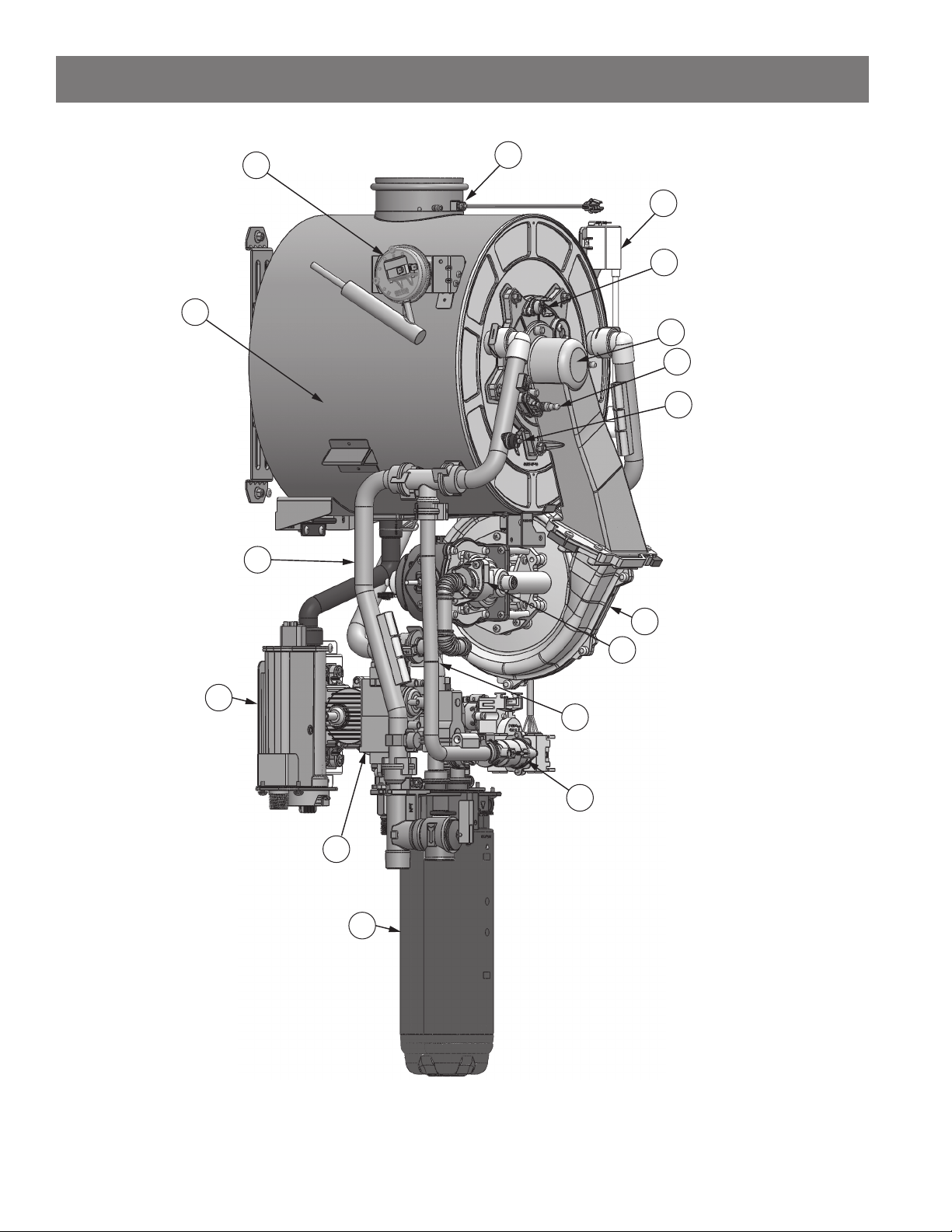
COMPONENT LIST
34
1
13
18
22
3
20
4
6
21
28
2
14
25
7
12
Residen al Gas Water Heater Use and Care Guide • 67
Page 68
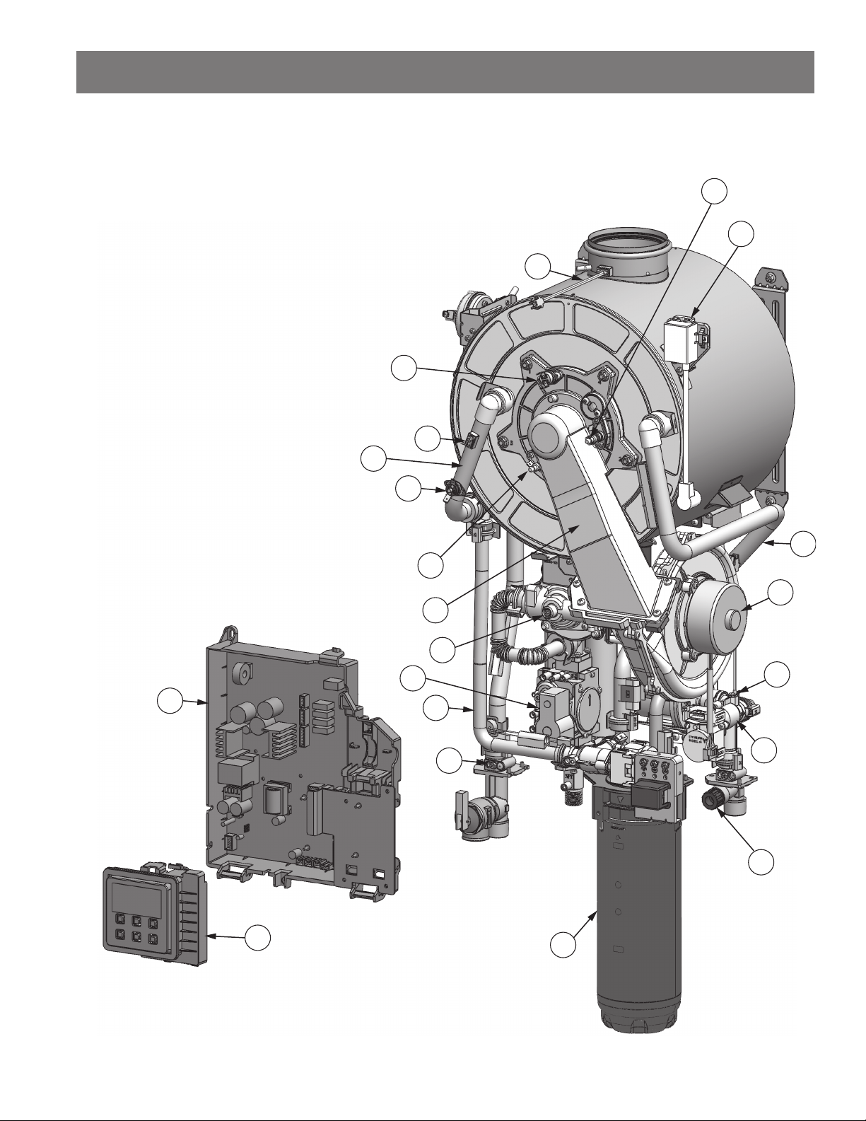
COMPONENT LIST
19
22
18
3
5
15
6
16
4
21
20
28
7
9
14
27
26
24
10
8
68 • Residen al Gas Tankless Water Heater Use and Care Guide
12
Page 69
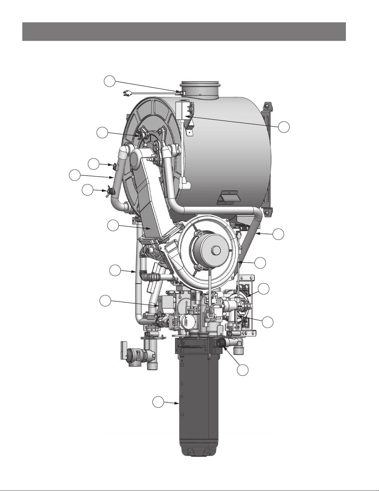
18
COMPONENT LIST
15
3
22
5
6
20
16
21
14
23
7
12
24
10
Residen al Gas Tankless Water Heater Use and Care Guide • 69
Page 70
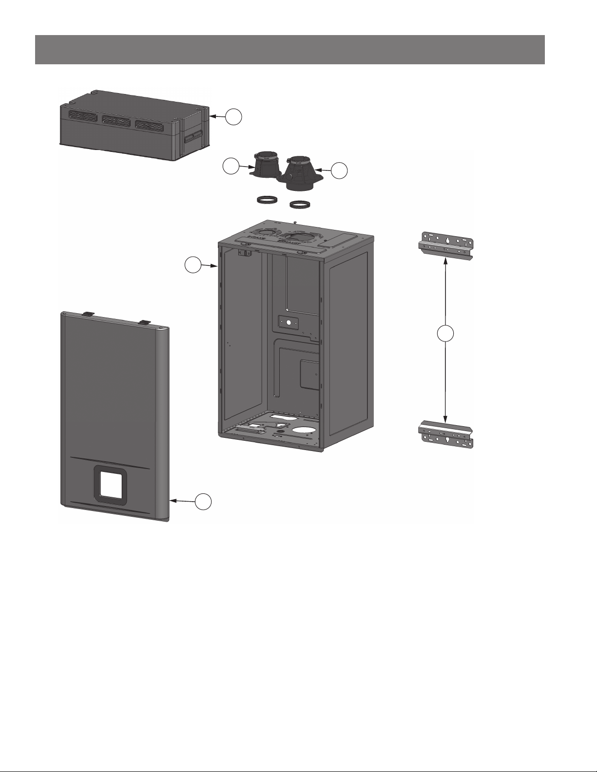
COMPONENT LIST
33
17
32
31
30
29
70 • Residen al Gas Tankless Water Heater Use and Care Guide
Page 71
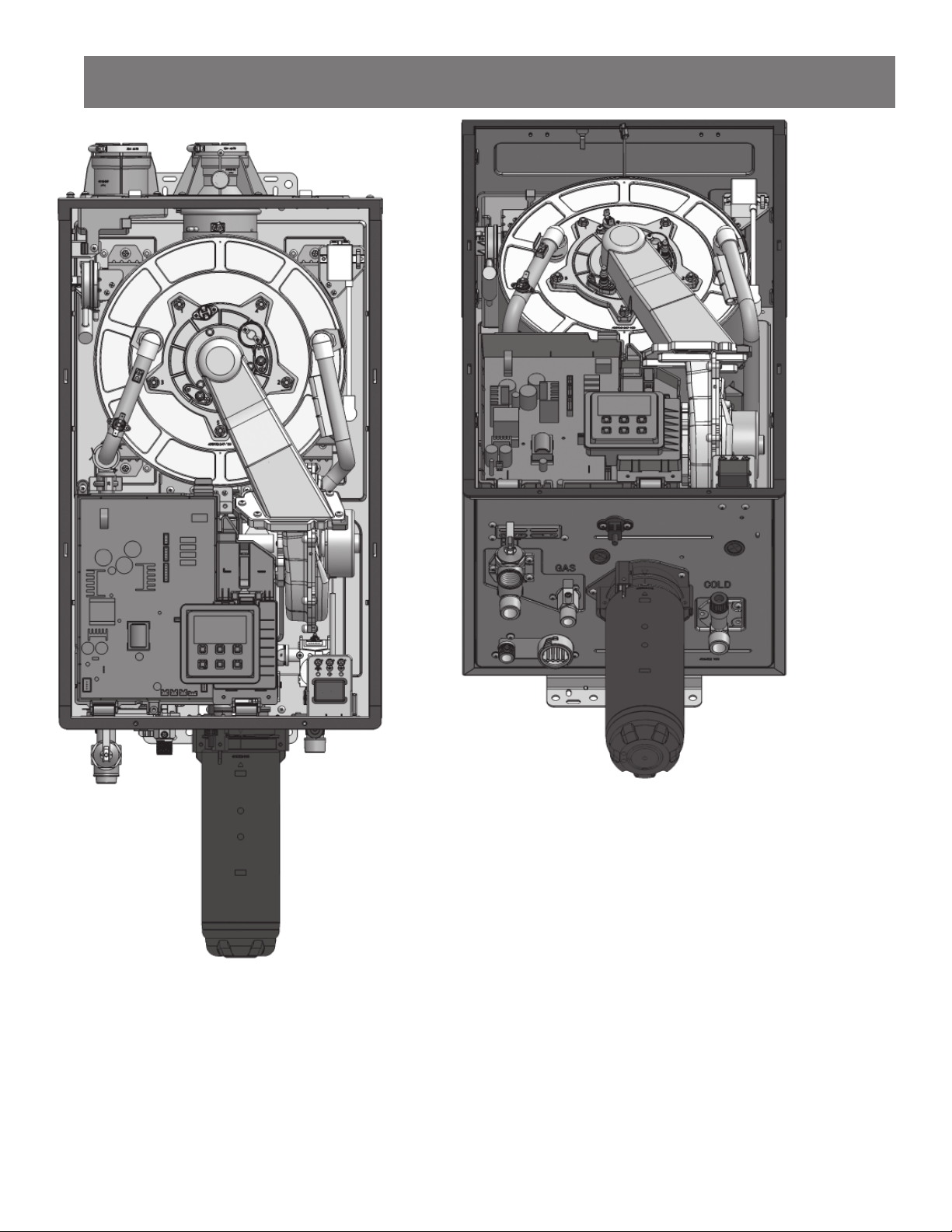
COMPONENT LIST
Residen al Gas Tankless Water Heater Use and Care Guide • 71
Page 72
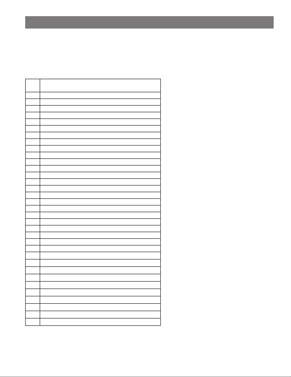
COMPONENT LIST
When ordering repair parts, always give the following informa on:
1. Model and serial numbers. This info should be on the le side of the water heater
2. Part(s) descrip on
Item
Component List
No.
1 AIR PRESSURE SWITCH
2 CONDENSATE TRAP
3 BURNER DOOR HI-LIMIT
4 FLAME SENSOR
5 HEAT EXCHANGER THERMISTOR
6 HI-LIMIT SWITCH (MANUAL RESET)
7 GAS VALVE
8 USER INTERFACE
9 PRINTED CIRCUIT BOARD
10 INLET FILTER
11 BYPASS CARTRIDGE (NOT SHOWN)
12 X3® CARTRIDGE
13 OUTLET WATER TUBE
14 BYPASS WATER TUBE
15 HEAT EXCHANGER OUTLET WATER TUBE
16 INLET WATER TUBE
17 CASE (FRONT COVER NOT SHOWN FOR CLARITY)
18 EXHAUST THERMISTOR
19 IGNITER RODS
20 BURNER ASSEMBLY
21 FAN
22 IGNITER
23 PUMP
24 FLOW SENSOR/FLOW CONTROL VALVE ASSEMBLY
25 BYPASS VALVE
26 INLET THERMISTOR
27 OUTLET THERMISTOR
28 VENTURI ASSEMBLY
29 CASE FRONT COVER
30 MOUNTING BRACKETS
31 EXHAUST PORT
32 INLET PORT
33 OUTDOOR VENT CAP
34 HEAT EXCHANGER ASSEMBLY
72 • Residen al Gas Tankless Water Heater Use and Care Guide
Page 73
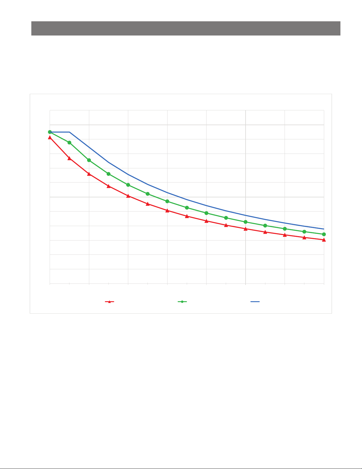
FLOW RATE
Flow Rate Capacity Chart
The chart is based on a properly sized gas line and installa on at 0-2,000 . (0-610 m). The water heater will de-rate approximately
3% (NG) or 4.5% (LP) per 1,000 . (305 m) of eleva on increase above 2,000 . (610 m).
THR Flow Rate Capacity Chart
12
11
10
9
8
7
6
5
Flow Rate (GPM)
4
3
2
1
0
30 35 40 45 50 55 60 65 70 75 80 85 90 95 100
Temperature Rise (°F)
THR-160 THR-180 THR-199
Residen al Gas Tankless Water Heater Use and Care Guide • 73
Page 74

Copyright © 2024, A. O. Smith.
All Rights Reserved
 Loading...