

Page 1
COMMERCIAL GAS WATER HEATERS
SERVICE HANDBOOK
HIGH EFFICIENCY
FOR MODELS:
• SUF60120
• SUF100150
• SUF100199
• SUF100250
• SUF130300
• SUF130400
COMMERCIAL GAS SERIES
PRINTED 0509 198152-002
1
Page 2

ULTRAFORCE COMMERCIAL GAS WATER HEATER
SUF 120 thru 400 SERVICE HANDBOOK
TABLE OF CONTENTS
INTRODUCTION...............................................................2
QUALIFICATIONS............................................................2
TOOLS REQUIRED.........................................................3
GENERAL INFORMATION................................................4
GAS PRESSURE SPECIFICATIONS ................................4
INSTALLATION QUICK TIPS – SUF 120 and 150 GAS
PRESSURE .....................................................................5
ADJUSTMENT PROCEDURE: .........................................5
GAS PRESSURE .............................................................5
SUF120 AND 150 MODELS..............................................5
HIGH ALTITUDE INSTALLATIONS ...................................5
SUF 120 - 150 .................................................................5
INSTALLATION QUICK TIPS - SUF 199 AND 250 GAS
PRESSURE .....................................................................6
ADJUSTMENT PROCEDURE:..........................................6
GAS PRESSURE .............................................................6
SUF 199 AND 250 MODELS ............................................6
HIGH ALTITUDE INSTALLATION......................................6
INSTALLATION QUICK TIPS - SUF 300, 400 GAS
PRESSURE......................................................................7
ADJUSTMENT PROCEDURE:..........................................7
GAS PRESSURE..............................................................7
SUF 300,400,....................................................................7
HIGH ALTITUDE ADJUSTMENT ......................................7
SUF 300,400,....................................................................7
INSTALLATION TIPS - SUF 300, 400 ...............................8
VENTING TABLES SUF 120 – 250....................................9
VENTING TABLES SUF 300,400,.....................................9
VENTING - ALL MODELS – SINGLE PIPE POWER VENT –
USING ROOM AIR..........................................................10
VENTING – ALL MODELS – TWO PIPE DIRECT VENT –
USING OUTSIDE AIR.....................................................11
VENT TERMINATION – DIRECT VENT – ALL MODELS. .12
DIRECT VENTING – ALL MODELS.................................13
CONTROL OVERVIEW ..................................................14
CONTROL OVERVIEW – ALL MODELS..........................14
ADJUSTING TANK TEMPERATURE – OPERATING SET
POINT - DIFFERENTIAL.................................................15
CHANGING THE DISPLAY UNITS..................................16
FAULT AND WARNING CONDITIONS – ADVANCED
DIAGNOSTIC INFORMATION.........................................17
ACCESS TO THE CURRENT FAULT OR WARNING.......18
VIEWING THE FAULT HISTORY - VIEWING
INFORMATION ABOUT THE HEATER............................19
CONTROL SEQUENCE (TYPICAL ALL MODELS).........20
CONTROL SEQUENCE FLOW CHART...........................21
CONTROLS – CENTRAL CONTROL BOARD – CCB ......22
CONTROLS – GAS VALVE SUF 120...............................23
CONTROLS – GAS VALVE SUF 150...............................23
CONTROLS – GAS VALVE SUF 199 and 250..................24
ADJUSTMENT PROCEDURE:........................................24
GAS PRESSURE ...........................................................24
SUF 199 AND 250 MODELS ..........................................24
CONTROLS – GAS VALVE SUF 199 and 250..................25
CONTROLS – GAS VALVE , ORIFICE CHART–
SUF300,400,...................................................................26
CONTROLS – PRESSURE SWITCHES – ALL MODELS..27
CONTROLS – PRESSURE SWITCHES – SUF 120 through
250.................................................................................28
CONTROLS – PRESSURE SWITCHES – SUF 300,400,. .29
CONTROLS – CONNECTIONS, IGNITER, FLAME
SENSOR, SIGHT GLASS, POWERED ANODES.............30
HOT SURFACE IGNITER / FLAME SENSOR / CONTROL
TIMING...........................................................................31
BLOWER SPEED CONTROL SUF 199 AND 250.............32
VARIABLE FREQUENCY DRIVE – SUF 400...................33
VARIABLE FREQUENCY DRIVE - BLOWER SPEED AND
PRESSURE READINGS..................................................34
WIRING DIAGRAM – SUF 120 – 300 ..............................35
WIRING DIAGRAM – SUF 400,.......................................36
State Water Heaters – Technical Training Department 1 Ashland City, Tennessee © 2009
Servicing should only be performed by a Qualified Service Agent 198152-002
Page 3

INTRODUCTION
ULTRAFORCE COMMERCIAL GAS WATER HEATER
SUF 120 thru 400 SERVICE HANDBOOK
The service handbook is designed to aid in
servicing and trou bleshooting S tate W ater
Heaters Ultra Force SUF commercial water
heaters i n t he f ield. No duplication or
reproduction of t his bo ok m ay be m ade
without the ex press w ritten authorization o f
State Water Heaters .
The fol lowing tex t and i llustrations w ill
provide you with a step by step procedure to
verify pr oper i nstallation, opera tion, and
troubleshooting procedures. Additional quick
reference da ta i s i ncluded to ass ist you in
servicing these products.
The information contai ned i n this handbook
is designed to answer co mmonly face d
situations enc ountered in the ope ration of
this product l ine and is not meant to be all
QUALIFICATIONS
inclusive. If you are experiencing a problem
not covered in this handbook, please contact
State Water Heaters Technical Information at
1-800-365-0024, by e mail at
help@statewaterheaters.com
or your local
State Water Heater representative for further
assistance.
Our website:www.statewaterheaters.com
is also a resource for installation and service
information. Thi s handbook i s i ntended for
use by licensed plumbing professionals and
reference should be made to the installation
manual accom panying the prod uct. This
handbook contains supplemental information
to the produ ct’s i nstallation and ope ration
manual.
ANSI Z223.1 Sec 3.3.83
"Qualified Agency"
"Any individual, firm, corporation or company
that ei ther i n person o r through a
representative i s e ngaged i n an d i s
responsible for (a) the installation, testing or
replacement of g as p iping or (b) the
connection, i nstallation, testing, re pair or
servicing of appliances and equipment; that
is experienced i n such work; that is familiar
with all precautions required; and that has
complied w ith al l the re quirements o f the
authority having jurisdiction."
Service of this water heater requires ability
equivalent to th at of a Qual ified S ervice
Agent (l icensed t radesman) i n the fi eld
involved. Installation skills such as plumbing,
air supp ly, vent ing, gas s upply, e lectrical
supply are r equired i n addition to electrical
testing ski lls. S ome pro ducts m ay requ ire
combustion testi ng equipment and
certification. If you do not possess these
skills or do not h ave the pr oper t ools y ou
should not attem pt to serv ice thi s w ater
heater.
State Water Heaters – Technical Training Department 2 Ashland City, Tennessee © 2009
Servicing should only be performed by a Qualified Service Agent 198152-002
Page 4
ULTRAFORCE COMMERCIAL GAS WATER HEATER
SUF 120 thru 400 SERVICE HANDBOOK
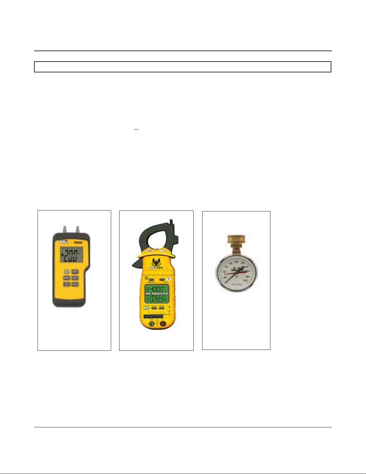
TOOLS REQUIRED
● ELECTRICAL MULTIMETER CAPABLE OF MEASURING CONTINUITY/ OHMS, AC
& DC VOLTS, AMPERES, MICROAMPERES, MILLIVOLTS, and FREQUENCY(Hz)
○ UEi Model DL289 or equivalent
● DIGITAL MANOMETER + 60” W. C. in .01” increments
Note: A digital manometer is required for testing pressure switches and can replace
a gas pressure gauge, draft gauge or slack tube manometer for checking gas
pressure.
○ UEi model EM200 or equivalent
● WATER PRESSURE GAUGE w/ LAZY HAND AND HOSE BIBB CONNECTION
● THERMOMETER
● 1-1/16 INCH SOCKET WITH EXTENSION FOR ANODE REPLACEMENT
● SET OF NUMBERED DRILL BITS
WATER PRESSURE
TEST GAUGE W/ LAZY
HAND AND HOSE BIBB
CONNECTION
DIGITAL MANOMETER
DIGITAL MULTIMETER
State Water Heaters – Technical Training Department 3 Ashland City, Tennessee © 2009
Servicing should only be performed by a Qualified Service Agent 198152-002
Page 5

ULTRAFORCE COMMERCIAL GAS WATER HEATER
SUF 120 thru 400 SERVICE HANDBOOK
GENERAL INFORMATION
INSTALLATION REQUIREMENTS FOR THE
COMMO NWEALTH OF MASSACHUSETTS
For al l side w all terminated, hor izontally vented
power v ent, direct vent, and power direct v ent gas
fueled w ater heat ers installed i n ev ery dwelling,
building or structure used in w hole or i n p art for
residential pur poses, including t hose ow ned or
operated by the Commonwealth and where the side
wall exhaust vent termination is less than seven (7)
feet above finished grade in the area of the venting,
including but not limited to decks and porches, the
following requirements shall be satisfied:
INSTA LLATION OF CARBON MONOXIDE
DETECTORS
At the time of installation of the side wall horizontal
vented gas fueled equipment, the installing plumber
or gas fitter s hall observe that a hard wired carbon
monoxide detector with an alarm and battery backup is in stalled on t he f loor le vel wh ere t he g as
equipment is t o b e i nstalled. In add ition, t he
installing plumber or gas fitter shall obs erve t hat a
battery operated or har d w ired carbon monoxide
detector w ith an al arm i s i nstalled on eac h
additional level of the dwelling, building or structure
served by the sidewall horizontal vented gas fueled
equipment. It s hall b e the re sponsibility o f the
property owner to secure t he services of q ualified
licensed pr ofessionals for the i nstallation of har d
wired carbon monoxide detectors. In the event that
the s ide wall hor izontally v ented gas fueled
equipment is installed i n a c rawl space or an attic,
the hard wired carbon monoxide detector with alarm
and battery back-up may be installed on the nex t
adjacent f loor l evel. I n t he e vent t hat the
requirements of this subdivision can not be met at
the t ime of c ompletion o f i nstallation, t he ow ner
shall have a period of thirty (30) days to comply with
the a bove requirements p rovided t hat dur ing said
thirty ( 30) day p eriod, a bat tery op erated carbon
monoxide detector with an alarm shall be installed
APPROVED CARBON MONOXIDE DETECTORS
Each carbon monoxide de tector as r equired in
accordance with the above provisions shall comply
with N FPA 720 and be AN SI/UL 20 34 listed and
CSA certified.
SIGNAGE
A m etal or p lastic i dentification plate s hall b e
permanently mounted to the exterior of the b uilding
at a minimum height of eight ( 8) feet ab ove grade
directly in line with the exhaust vent terminal for the
horizontally vented gas fueled heating appliance or
equipment. The sign shall read, in print size no less
than one-half (1/2”) inch in size,
“GAS VENT DIRECTLY BELOW. KEEP CLEAR
OF ALL OBSTRUCTIONS.”
GAS PRESSURE SPECIFICATIONS
MODELS
Maximum Gas Supply Pressure
Nominal Gas Suppl y Pressure
Minimum Gas Supply Pressure
(Low Gas Press. Switch
Setting)
Manifold Pressure
Natural
120-150
10.5” W C
(2.59kPa)
7.0”WC
(1.74kPa)
4.8”WC
(1.20kPa)
4.0”WC
(0.98kPa)
State Water Heaters – Technical Training Department 4 Ashland City, Tennessee © 2009
Servicing should only be performed by a Qualified Service Agent 198152-002
Propane
120-150
14.0“WC
( 3.45kPa)
11.0“WC
( 2.74kPa)
8.5“WC
( 2.12kPa)
10.0“WC
(2.49 kPa)
Natural
199-250
10.5“WC
(2.59kPa)
7.0“WC
(1.74kPa)
4.8”WC
(1.20kPa)
0“WC
( 0 kPa)
Propane
199-250
14.0“WC
( 3.45kPa)
11.0“WC
( 2.74kPa)
8.5“WC
( 2.12kPa)
0“WC
( 0 kPa)
Natural
300/400/500
11.0”WC
(2.74kPa)
7.0”WC
(1.74kPa)
5.2”WC
(1.54kPa)
4.00“WC
( 1.25kPa)
Propane
300/400/500
14.00”W C
(3.49kPa)
11.0”WC
(2.74kPa)
11.0“WC
( 2.74kPa)
10.0“WC
( 2.49kPa)
Page 6
ULTRAFORCE COMMERCIAL GAS WATER HEATER
SUF 120 thru 400 SERVICE HANDBOOK
INSTALLATION QUICK TIPS – SUF 120 and 150 GAS PRESSURE
ADJUSTMENT PROCEDURE:
GAS PRESSURE
SUF120 AND 150 MODELS
a. Attach a pressure gauge (manometer) to the
manifold pressure tap and refer to page 4 for correct
pressure.
Main line gas pressure to the water heater for natural
gas should be between a maximum of 10.5"W.C.
(2.59kPa) for natural gas, 14.0"W.C.(3.45kPa) for
propane and a minimum of 4.8W.C.(1.18kPa) for
Natural Gas, and 8.5"W.C. (2.08kPa) for Propane
Gas.
A supply gas pressure regulator
(service regulator) must be installed on
the gas supply line within 10' (305 cm)
of the unit.
Also see gas pressure specification table on page 4.
1.Check gas line pressure with a manometer.
2.Check manifold pressure gauge (manometer)
connected to the manifold pressure tap on the gas
control valve,
If full rate adjustment is required, remove cover screw
from top of the gas control valve. Using a small
screwdriver, turn adjusting screw clockwise to
increase or counterclockwise to decrease gas
pressure to obtain 4.0" W.C.(1 K pa) for natural gas
and 10.0" W.C. (2.5 kPa) for L.P. Gas.
3. Cycle the burner on and off several times to check
its operation.
4. Check the operation of the limit and operating
controls.
5. Check the vent system seams and joints and
ensure that there is no discharge of flue products into
the room.
6. Check the input rate.
HIGH ALTITUDE INSTALLATIONS
SUF 120 - 150
For appliance installation locations with elevations
above 6,500 feet (1982 meters) consult the “High
Altitude Installation” section of the owners manual.
b. Use this formula to “clock” the meter. Be sure
other gas consuming appliances are not operating
during this interval.
Btuh = 3600 X H/ T
T = Time in seconds to burn 1 cubic foot of gas.
(With a stopwatch read the gas meter and measure
the amount of time required for the heater to consume
1 cubic foot of gas.)
H = Heating value of gas (in Btu’s per cubic foot of
gas).
Btuh = Actual heater input rate, in Btuh.
EXAMPLE: (Using SUF-150 heater)
T = 25.25 seconds
H = 1050 Btu/ft.3
BTUH = ?
Compare result to the de-rated input required for
the elevation at the installat ion location.
Should it be necessary to adjust the gas pressure to
the burner, to obtain the full input rate, the steps below
should be followed:
c. Remove the pressure regulator cover screw and
adjust the pressure by turning the adjusting screw with
a small screwdriver. Do not exceed 4.0" (1 kPa)
natural gas models and 10.0" w.c. (2.5kPa) on the
propane models. Clockwise to increase gas pressure
and input rate. Counterclockwise to decrease gas
pressure and input rate.
d. “Clock” the meter as in step (b) above.
e. Repeat steps (c) and (d) until the specified input
rate is achieved.
f. Turn the manual gas valve to “OFF”. Replace the
pressure regulator cover screw. Remove the pressure
gauge or manometer from the manifold pressure tap.
Replace the set screw in the manifold pressure tap. If
the gas pressure regulator cannot be adjusted to give
the full input rating with sufficient gas pressure at the
valve, check to ensure the unit is equipped with the
correct orifice.
State Water Heaters – Technical Training Department 5 Ashland City, Tennessee © 2009
Servicing should only be performed by a Qualified Service Agent 198152-002
Page 7
ULTRAFORCE COMMERCIAL GAS WATER HEATER
SUF 120 thru 400 SERVICE HANDBOOK
INSTALLATION QUICK T IPS - SUF 199 AND 250 GAS PRESSURE
ADJUSTMENT PROCEDURE:
GAS PRESSURE
SUF 199 AND 250 MODELS
IMPORTANT NOTE
THE SUF 199 AND 250 MODELS
INCORPORATE A NEW GAS CONTROL,
WHICH OPERATES AT A MANIFOLD
PRESSURE OF 0" W.C. (0 kPa) FOR BOTH
NATURAL AND PROPANE GAS. SEE T HE
GAS PRESSURE CHART ON PAGE 4.
THESE MODELS ARE CONFIGURED
PRIOR TO BEING SHIPPED FROM THE
FACTORY AND NO ADJUSTMENTS ARE
NECESSARY PRIOR TO STARTUP. THE
CONTROLLER MONITORS T HE AIR FLOW
AND MAKES ADJUSTMENTS TO THE FAN
SPEED WHICH IN EFFECT CONTROLS
THE AMOUNT OF GAS FLOW.
THEREFORE, THE UNIT WILL SELF
ADJUST TO ACQUIRE THE CORRECT
AMOUNT OF INPUT.
"Supply gas pressure to the water heater
must not exceed a maximum of 10.5" w.c.
(295kPa) for natural gas, or 14" w.c. (3.45
kPa) for propane. The minimum supply gas
pressure is 4.8" w.c. (1.20 kPa) for natural
gas and 8.5" w.c. (2.12 kPa) for propane
gas."
HIGH ALTITUDE INSTALLATION
The SUF 199 and 250 models are suitable
for installation up to 10,100 feet above sea
level with no adjustments.
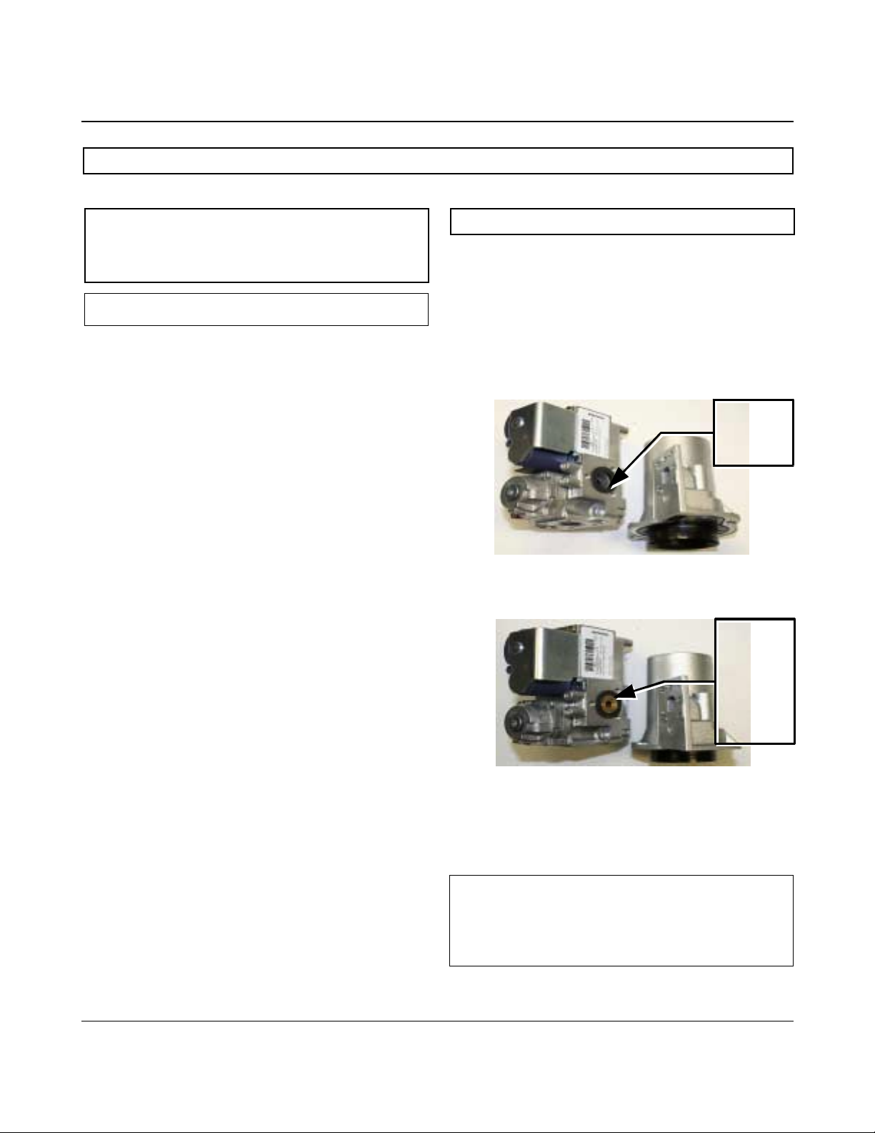
GAS ORIFICE
The SUF 199 and 250 models do not have a
natural gas orifice. A .230” orifice is used on
LP gas models.
Venturi
Gasket
w/o orifice
Gas Control Without Orifice
Natural Gas
Venturi
Gasket w/
LP Gas
Orifice
(.230”
Brass)
Gas Control with .230” LP Orifice
Once the unit is installed and filled with water
and the inlet pressures confirmed, simply
turn the switch "on" and observe operation.
Cycle the unit "off" and "on" several times to
ensure proper operation.
A supply gas pressure regulator
(service regulator) must be installed on
the gas supply line within 10' (305 cm)
of the unit.
State Water Heaters – Technical Training Department 6 Ashland City, Tennessee © 2009
Servicing should only be performed by a Qualified Service Agent 198152-002
Page 8

ULTRAFORCE COMMERCIAL GAS WATER HEATER
SUF 120 thru 400 SERVICE HANDBOOK
INSTALLATION Q UICK TIPS - SUF 300, 400 GAS PRESSURE
ADJUSTMENT PROCEDURE:
GAS PRESSURE
SUF 300,400,
A minimum dynamic gas suppl y pressure of
5.2" w.c. (1.29 kPa) for Natural Gas and 11"
w.c. (2.74 kP a) for LP Gas is requir ed befo re
making any adjustment to th e gas control
pressure regulator. Attempts to adjust the
regulator during periods of low gas supply
pressure could result in over firing of the water
heater when the gas supply pressure returns to
normal.
1. Check gas line pressure with a manometer,
adjust the gas supply line pressure Gas Pressure
table on page 4.
2. Check manifold pressure using a pressure
gauge (manometer) connected to the manifold
pressure tap on the gas control valve, If full rate
adjustment is required, remove cover screw from
top of the gas control valve. Using a small
screwdriver, turn adjusting screw clockwise to
increase or counter clockwise to decrease gas
pressure to obtain 4.0" w.c. (0.996 kPa) for
Natural Gas and 10" w.c. (2.49kPa) for LP gas.
3. Cycle the burner on and off several times to
check its operation.
4. Check the operation of the limit and operating
controls.
5. Check the vent system seams and joints and
ensure that there is no discharge of flue products
into the room.
6. Check the input rate as shown on page 5.
HIGH ALTITUDE ADJUSTMENT
SUF 300,400,
For high altitude adjustments, contact the
help line on the front of the water heater or
contact help@statewaterheaters.com .
State Water Heaters – Technical Training Department 7 Ashland City, Tennessee © 2009
Servicing should only be performed by a Qualified Service Agent 198152-002
Page 9
ULTRAFORCE COMMERCIAL GAS WATER HEATER
SUF 120 thru 400 SERVICE HANDBOOK
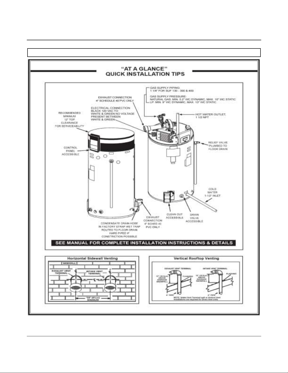
INSTALLATION TIPS - SUF 300, 400
State Water Heaters – Technical Training Department 8 Ashland City, Tennessee © 2009
Servicing should only be performed by a Qualified Service Agent 198152-002
Page 10
ULTRAFORCE COMMERCIAL GAS WATER HEATER
SUF 120 thru 400 SERVICE HANDBOOK
VENTING TABLES SUF 120 – 250
Maximum equivalent feet of intake and vent pipe using 3” PVC is 50 feet (15.2m). Equivalent feet
must include any 90° elbows (two 45° elbows equal one 90° elbow). Three inch diameter 90° elbows
are equivalent to 5' (1.5m) of pipe.
Maximum equivalent feet of intake and vent pipe using 4” PVC is 120 feet (36.6m).
Equivalent feet must include any 90° elbows (two 45° elbows equal one 90° elbow). Four inch
diameter 90° elbows are equivalent to 5' (1.5m) of pipe.
Vent Length Table Equi valent Feet (Meters) 120 thro ugh 25 0
Number of 90°
Elbows
ONE (1) 7/2.1 45/13.7 115/35
TWO (2) 7/2.1 40/12.2 110/33.5
THREE (3) 7/2.1 35/10.7 105/ 32
FOUR (4) 7/2.1 30/9.1 100/30.5
FIVE (5) 7/2.1 --- 95/29
SIX (6) 7/2.1 --- 90/27.4
3" Minimum
Pipe (Ft./M.)
3" Maximum
Pipe (Ft./M.)
VENTING TABLES SUF 300,400,
Vent Length Table Equivalent Feet (Meters) 300,400,
Number of
90°Elbows
ONE (1) 65' / 19.7 m
TWO (2) 60' / 18.2 m
Maximum Feet / meters of Pipe
4" PVC
4"Maximum
Pipe (Ft./M.)
THREE (3) 55' / 16.7 m
FOUR (4) 50' / 15.2 m
FIVE (5) 45' / 13.6 m
SIX (6) 40' / 12.1 m
State Water Heaters – Technical Training Department 9 Ashland City, Tennessee © 2009
Servicing should only be performed by a Qualified Service Agent 198152-002
Page 11
ULTRAFORCE COMMERCIAL GAS WATER HEATER
SUF 120 thru 400 SERVICE HANDBOOK
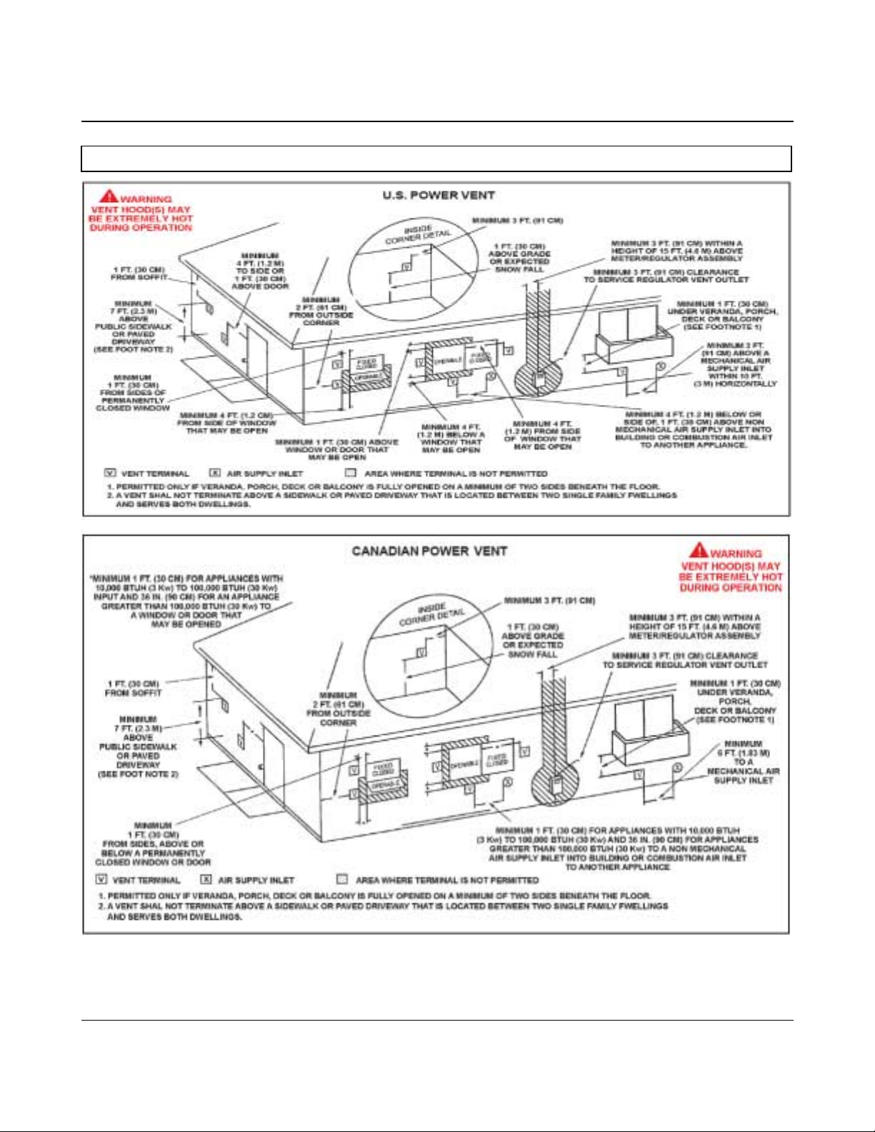
VENTING - ALL MODELS – SINGLE PIPE POWER VENT – USING ROOM AIR
State Water Heaters – Technical Training Department 10 Ashland City, Tennessee © 2009
Servicing should only be performed by a Qualified Service Agent 198152-002
Page 12
ULTRAFORCE COMMERCIAL GAS WATER HEATER
SUF 120 thru 400 SERVICE HANDBOOK
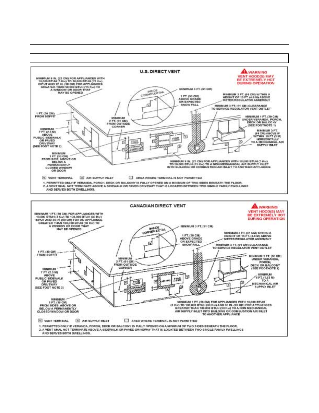
VENTING – ALL MODELS – TWO PIPE DIRECT VENT – USING OUTSIDE AIR
State Water Heaters – Technical Training Department 11 Ashland City, Tennessee © 2009
Servicing should only be performed by a Qualified Service Agent 198152-002
Page 13

ULTRAFORCE COMMERCIAL GAS WATER HEATER
SUF 120 thru 400 SERVICE HANDBOOK
VENT TERMINAT ION – DIRECT VENT – ALL MODELS
WHEN LOCATING THE TERMINALS ON A SIDEWALL, THE FOLLOWING SPECIFICATIONS
PERTAINING TO TERMINAL LOCATION MUST BE FOLLOWED.
1. The intake vent terminal and the exhaust vent terminal must terminate on
the same exterior wall and must be located at a minimum of 24" (61cm)
from the vertical centerline of the exhaust vent terminal (see Figure 9).
In colder climates increasing the 24" (61cm) minimum will reduce
possibility of frost over from side winds blowing exhaust vapors to the
air intake of the direct vent.
2. The horizontal centerline of the intake vent terminal may not be located
lower than the horizontal centerline of the exhaust vent terminal
State Water Heaters – Technical Training Department 12 Ashland City, Tennessee © 2009
Servicing should only be performed by a Qualified Service Agent 198152-002
Page 14

ULTRAFORCE COMMERCIAL GAS WATER HEATER
SUF 120 thru 400 SERVICE HANDBOOK
DIRECT VENTING – ALL MODELS
The air intake provided on the unit contains a mesh screen to prevent large particles from entering the
unit. WHEN THE UNIT IS TO BE SET UP AS A DIRECT VENT, THE BALANCE PLATE AND MESH
SCREEN MUST BE REMOVED BEFORE GLUING PIPE TO THE CONNECTOR. THE INLET VENT
PIPE MAY THEN BE GLUED TO THE AIR INTAKE PROVIDED ON THE UNIT.
45° PVC Elb ow
Remove the balance plate and mesh
screen before gluing intake air pipe
to the fitting.
3” 120-25 0
4” 300- 400
Two 3” or 4” 45° PVC elbows with mesh screens are provided with each unit. Both elbows are
to be used in direct vent applications. The screens are provided to keep vermin and large
debris from entering the intake air and exhaust vent runs.
State Water Heaters – Technical Training Department 13 Ashland City, Tennessee © 2009
Servicing should only be performed by a Qualified Service Agent 198152-002
Page 15

ULTRAFORCE COMMERCIAL GAS WATER HEATER
SUF 120 thru 400 SERVICE HANDBOOK
CONTROL OVERVIEW
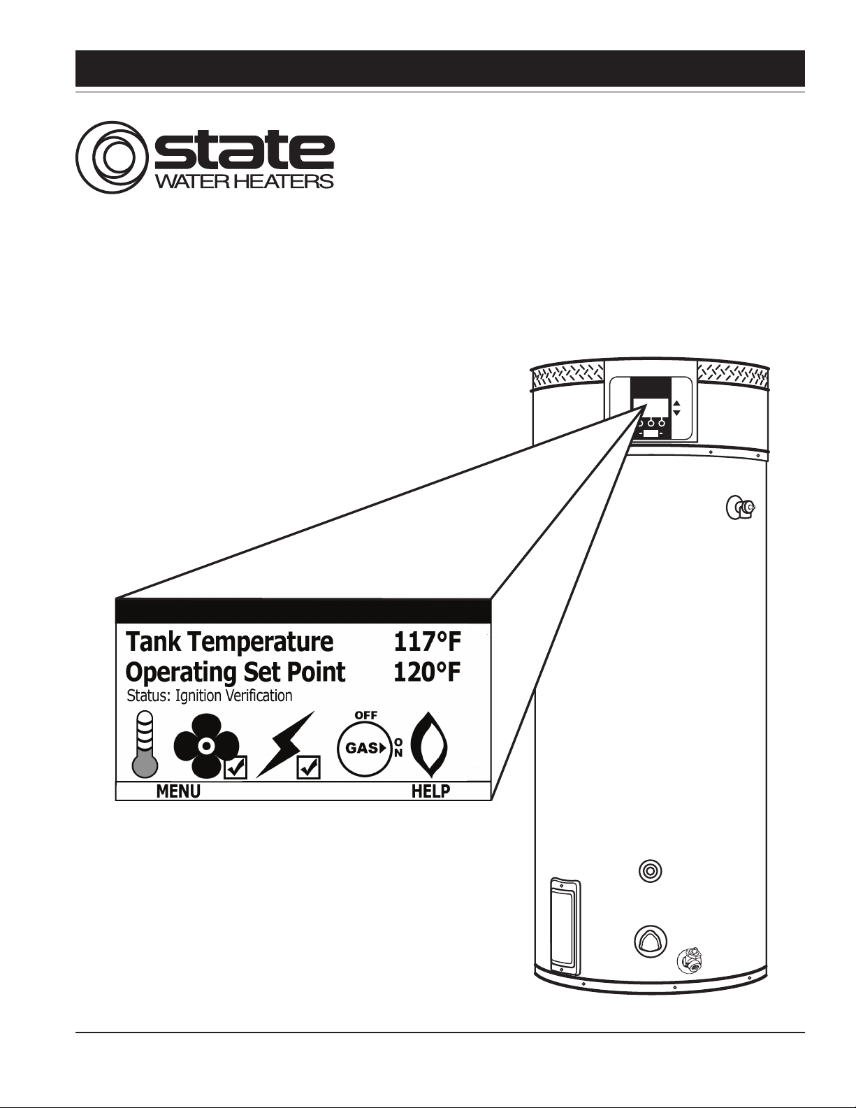
CONTROL OVERVIEW – ALL MODELS
Interaction with the water heater controller is done
through an LCD display called the Universal
Interf a c e Mod ule (UIM).This screen is also referred to
as the “desktop” or “desktop menu”. Up and down
buttons and three operation buttons allow navigation
through the control menus and to make adjustments to
the water heater. Operation of the three lower buttons
is defined immediately above them on the screen.
While the water heater is operating, the user interface
will display the desktop screen (if there are no active
faults or warnings).
● An example of this screen is shown below.
● The first temperature on this screen is the
temperature of the water inside the tank.
● The second temperature on this screen is the
Operating Set Point.
● The Operating Set Point is the temperature at
which the water heater will maintain the water
inside the tank.
● The third line on the screen is a text
description of the Operational State of the
water heater. The operating state of the water
heater is also indicated graphically by status
icons.
The table of status icons describes graphically
operational details of the water heater. Below is a
legend of all the status icons:
Status
Description
Icon
The t emperature o f the water in the tank has
fallen and the water heater will now initialize a
new heating cycle.
The t emperature o f the water in the tank has
reached the Operating Set Point.
The cont rol i s un able t o i nitiate any f urther
heating cycles. This is usually caused by a fault
condition detected by the control, but can also
occur when an external system (like an energy
management sys tem) has as ked t he w ater
heater to discontinue any further heat cycles.
The blower is being energized.
The blower pressure switch has been made.
The igniter has been energized.
The igniter has been energized and sufficient
curr ent for ignition has been detected.
^
The cont rol has requested that the gas valve
be turned on.
The control has sensed flame in the burner.
The control has detected a fault condition. A
fault condition will cause the water heater to
discontinue operation.
OPERATION
BUTTONS
UP AND
DOWN
BUTTONS
State Water Heaters – Technical Training Department 14 Ashland City, Tennessee © 2009
Servicing should only be performed by a Qualified Service Agent 198152-002
The control has detected a warning condition.
These conditions w ill not cause t he water
heater to discontinue further heating cycles, but
does merit attention.
Page 16

ULTRAFORCE COMMERCIAL GAS WATER HEATER
SUF 120 thru 400 SERVICE HANDBOOK
ADJUSTING T ANK TEMPERATURE – OPERATING SET POINT - DIFFERENTIAL
The Operating Set Point of this water heater
determines the regulated temperature for the water in
the tank. This parameter is adjusted in the desktop
Temperature menu. Items in this menu allow you to
monitor different temperature readings in the tank
along with adjusting the Operating Set Point and
Differential.
ACTION:
From the desktop screen, press Menu.
DISPLAY:
ACTION:
Press Change then use the UP and DOWN buttons to
change the temperature Set Point.
DISPLAY:
Note: This procedure can also be used to change the
Differential. The tank Upper and Lower Temperatures
are not user changeable. They are determined by the
temperature probes on the heater.
ACTION:
From the Main Menu, press Select to enter the
"Temperatures" screen.
DISPLAY:
ACTION:
Press Update to accept the change or Cancel to reset
it.
DISPLAY:
State Water Heaters – Technical Training Department 15 Ashland City, Tennessee © 2009
Servicing should only be performed by a Qualified Service Agent 198152-002
Page 17

ULTRAFORCE COMMERCIAL GAS WATER HEATER
SUF 120 thru 400 SERVICE HANDBOOK
CHANGING THE DISPLAY UNITS
The desktop menu has the option of selecting
between degrees Fahrenheit and degrees Celsius for
temperature displays. This can be found in the
“Display Settings” menu. Also in this menu, you may
adjust how the back-light operates and the contrast of
the LCD screen.
ACTION:
From the Main Menu, press the DOWN button to
highlight "Display Settings" then press Select.
DISPLAY:
ACTION:
Press Update to accept the change or Cancel to
reject it.
DISPLAY:
ACTION:
Use the UP and DOWN buttons to highlight the
desired setting. Then press Change. Again, use the
UP and DOWN buttons to scroll through the options
for that setting.
DISPLAY:
State Water Heaters – Technical Training Department 16 Ashland City, Tennessee © 2009
Servicing should only be performed by a Qualified Service Agent 198152-002
Page 18

ULTRAFORCE COMMERCIAL GAS WATER HEATER
SUF 120 thru 400 SERVICE HANDBOOK
FAULT AND WARNING CONDITIONS – ADVANCED DIAGNOSTIC INFORMATION
This w ater heat er c ontrol has t he abil ity t o m onitor
almost all aspects of the w ater heater's oper ation. In
the c ase t hat there i s an undes irable or uns afe
condition t hat o ccurs, t he water heat er control will
detect t his c ondition and de termine the appropriate
action. T he w ater heat er c ontrol will di splay t he
information on the desktop in plain text that accurately
describes the condition and diagn ostics i nformation
that can be used to correct the issue.
There are t wo t ypes o f c onditions t hat c an oc cur
during operation. These are Warnings and Faults:
Warnings: This is a non-safety related condition that
the c ontrol has det ected t hat m ay c ause the w ater
heater to operate in a less than optimal condition, but
does not pose a safety concern.
NOTE: When t hese conditions oc cur, continued
heating cycles will continue and the heater will attempt
to regulate the water in the tank to the Operati ng Set
Point.
Example of a Warning:
Faults: This is a safety related condition that has been
detected by the heater.
NOTE: W hen these conditions occur, the water heater
WILL NOT CONTINUE any further heating cycles and
the water will no longer be heated until the condition is
corrected and, in most cases, power has been cycled.
Example of a Fault:
Advanced Diagnostic Information
When a fault or warning has been declared, advanced
information can be found in t he c ontrol. By pressing
the A dvanced but ton, det ailed i nformation can be
found regarding diagnosing and resolving the problem.
WARNING: Usage of the Advanced information
requires ability equivalent to that of a licensed
tradesmen in the field involved.
State Water Heaters – Technical Training Department 17 Ashland City, Tennessee © 2009
Servicing should only be performed by a Qualified Service Agent 198152-002
Page 19

ULTRAFORCE COMMERCIAL GAS WATER HEATER
SUF 120 thru 400 SERVICE HANDBOOK
ACCESS TO THE CURRENT FAULT OR WARNING
When a fault or warning has been detected by the
control it will automatically be displayed on the screen
and the back light will blink. If you choose to leave the
current fault or warning by pressing the Back key, you
can always return to the fault through the display
menu through the menu.
ACTION:
Press the DOWN button for more information.
DISPLAY:
ACTION:
To get to the current fault information screen, press
Menu.
DISPLAY:
State Water Heaters – Technical Training Department 18 Ashland City, Tennessee © 2009
Servicing should only be performed by a Qualified Service Agent 198152-002
Page 20

ULTRAFORCE COMMERCIAL GAS WATER HEATER
SUF 120 thru 400 SERVICE HANDBOOK
VIEWING THE FAULT HISTORY - VIEWING INFORMATION ABOUT TH E HEATER
The controller for this water heater will store a history
of ten of the last Fault and Warning conditions that
occurred. This is stored in the Fault History. The
information about the fault or warning will include
diagnostic information as well as an estimate of how
long ago the fault occurred.
ACTION:
Press the SELECT button for more information.
DISPLAY:
Viewi ng Inf ormation A bout t he W ater Heater
The control for this water heater monitors many
different aspects of the water to ensure safe and
optimal operation. Much of the information monitored
is available to view in two areas of the control. The
first is the "Heater Status" and; the second is
"Heater Informatio n. "
These items can be selected through the desktop
menu. In these menus, detailed information about the
water heater and the current status of specific
conditions can be found.
ACTION:
Press the DOWN key to scroll through the fault
history. If you select a specific fault or warning, you
may press the VIEW button to view details regarding
this fault.
DISPLAY:
State Water Heaters – Technical Training Department 19 Ashland City, Tennessee © 2009
Servicing should only be performed by a Qualified Service Agent 198152-002
Page 21

ULTRAFORCE COMMERCIAL GAS WATER HEATER
SUF 120 thru 400 SERVICE HANDBOOK
CONTROL SEQUENCE (TYPICAL ALL MODELS)
TYPICAL SEQUENCE
1. When the control is powered it should display
“waiting for connection” and “UIM v2.06”*. The
manufacturer and unit model will be next. The next
display will include water temperature, temperature
setting and heater status.
* This number may change as software revisions are
made.
2. The control performed selected system diagnostic
checks immediately upon power up. This includes
confirming the proper state of the air/gas switches and
ECO limit device and powered anodes.
3. If the control determines that the actual water
temperature inside the tank is below the programmed
temperature set-point less the differential, a call for
heat is activated.
4. If all checks are successfully passed, the
combustion blower is energized for the pre-purge
cycle.
5. When the pre-purge cycle is complete, power is
applied to the igniter element for the igniter warm-up
period.
10. The combustion blower will run for the duration of
the post purge cycle to purge the system of all
combustion gases. When the post purge cycle is
complete, the blower is de-energized and will coast to
a stop.
11. The control will now enter the idle state while
continuing to monitor the internal tank water
temperature and the state of other system devices. If
the temperature drops below the set-point value less
differential, the control will automatically return to
step 2 and repeat the entire operating cycle.
6. At the conclusion of the igniter warm-up period, the
gas valve will open, allowing gas to enter the burner
chamber.
7. The igniter will remain on for a short predetermined
time period, then will be turned off.
8. The control will monitor the flame sense probe to
confirm a flame is present. If a flame is not verified
within predetermined time period, the gas valve will
immediately be closed, and the blower will continue to
run for approximately 30 seconds inter-purge. The
control will try for ignition two more times before
Blow er icon
indicates
pow er to the
blow er
Check mark in the box
indicates the blow er
proving sw itch contacts
are made
Flame icon indicates
burner is ignited and
that flame has been
sensed.
lockout.
9. If a flame is confirmed, the control will enter the
heating mode where it will continue heating the tank
water until the set point temperature plus differential is
reached. At this point, the gas valve is closed and the
control enters the post-purge cycle.
State Water Heaters – Technical Training Department 20 Ashland City, Tennessee © 2009
Servicing should only be performed by a Qualified Service Agent 198152-002
Page 22

ULTRAFORCE COMMERCIAL GAS WATER HEATER
SUF 120 thru 400 SERVICE HANDBOOK
CONTROL SEQUENCE FLOW CHART
Power on
Control displays
model ,
temperat ure
setting and
st atus
If checks are not
passed the
control will
display an error
or warning .
The cont rol will
st ore an error
history to show
what fault occurred
and the time
elapsed since t he
fault.
The control
performs internal
system checks
and determines
tank temperat ure
is below s et point
If all checks are
passed and there is
a call for heat the
blower is ener gized
for a pre purge
cycle
When the pre
purge is complete
power is appl ied to
the i gnit er for
Warm-up.
At t he conclusion
of the igniter
warm up the gas
valve w il l open for
4 seconds .
If the control
senses f lame the
water heater will
fire unti l the set
point is reached .
If the c ontrol fai ls
to see flame the
blower will continue to
run for a 30 s econd
Inter purge . There will
be 3 trials f or ignit ion
before a fault is
declared .
At the c onclusion
of t he inter purge
the i gnit er will
warm and the gas
valve will open.
At t he conclusion
of t he heating
cycle the blower
will enter a post
purge cycle and
the control will
enter an idle state .
State Water Heaters – Technical Training Department 21 Ashland City, Tennessee © 2009
Servicing should only be performed by a Qualified Service Agent 198152-002
Page 23

ULTRAFORCE COMMERCIAL GAS WATER HEATER
SUF 120 thru 400 SERVICE HANDBOOK
CONTROLS – CENTRAL CONTROL BOARD – CCB
The Central Control Board or CCB is contained
in the housing shown below. Access to the
board and the wiring harness plugs can be
accomplished by removing two Phillips screws
holding the cover.
This view shows the cover removed from the
CCB.
Remove these
screws to release
cover
The CCB is controlled by the settings given
through the desk top menu (UIM). The CCB also
monitors all pressure switches, the hot surface
igniter, tank temperatures, the gas valve, the
anodes, and the flame sensor.
The CCB directly controls blower speed on the
SUF199 and 250 models and indirectly controls
blower speed on the SUF 400 by means of a
Variable Frequency Drive (see page 33).
Note: Improper operation may be the result of a
loose connection. Please check all wiring
connections and the power supply to the water
heater.
This is the back of the UIM.
State Water Heaters – Technical Training Department 22 Ashland City, Tennessee © 2009
Servicing should only be performed by a Qualified Service Agent 198152-002
Page 24

ULTRAFORCE COMMERCIAL GAS WATER HEATER
SUF 120 thru 400 SERVICE HANDBOOK
CONTROLS – GAS VALVE SUF 120
The gas control valve on the SUF 120 has a
built i n adj ustable pre ssure regulator. T he
adjustment screw is accessed by removing
the cap screw m arket regulator i n t he
illustration.
Inlet gas pressure may be read a t the inlet
pressure tap only if the manual shut off valve
(gas cock) i s in the “ON” position. Leaving
the knob in the “OFF” position will not allow
the bu rner to fi re an d w ill genera te a fault
code on th e UIM ( Universal I nterface
Module).
CONTROLS – GAS VALVE SUF 150
The gas control valve on the SUF 150 is has
a built in pressure regulator. The regulator
may be adjusted by removing the cap screw
marked “regulator” in the illustration.
Inlet gas pressure may be read at the i nlet
pressure tap only if the manual switch is set
the “ON” position.
State Water Heaters – Technical Training Department 23 Ashland City, Tennessee © 2009
Servicing should only be performed by a Qualified Service Agent 198152-002
Page 25

ULTRAFORCE COMMERCIAL GAS WATER HEATER
SUF 120 thru 400 SERVICE HANDBOOK
CONTROLS – GAS VALVE SUF 199 and 250
ADJUSTMENT PROCEDURE:
GAS PRESSURE
SUF 199 AND 250 MODELS
IMPORTANT NOTE
THE SUF 199 AND 250 MODELS
INCORPORATE A NEW GAS CONTROL,
WHICH OPERATES AT A MANIFOLD
PRESSURE OF 0"W.C. (0 kPa) FOR BOTH
NATURAL AND PROPANE GAS. SEE THE
GAS PRESSURE CHART ON PAGE 4.
THESE MODELS ARE CONFIGURED
PRIOR TO BEING SHIPPED FROM THE
FACTORY AND NO ADJUSTMENTS ARE
NECESSARY PRIOR TO STARTUP. THE
CONTROLLER MONITORS THE AIR FLOW
AND MAKES ADJUSTMENTS TO THE FAN
SPEED WHICH IN EFFECT CONTROLS
THE AMOUNT OF GAS FLOW.
THEREF ORE, THE UNIT WILL SELF
ADJUST TO ACQUIRE T HE CORRECT
AMOUNT OF INPUT.
Supply gas pressure to the water heater for
natural gas should be between a maximum
of 10.5" (2.59kPa for natural gas) W.C.
(14.0"/3.45kPa for propane) and a minimum
as shown on page 4: that is, for Natural Gas
4" (.98kPa) W.C. And 9.0" (1.97kPa) for
Propane Gas. The inlet gas pressure must
not exceed the maximum value.
Once the unit is installed and filled with water
and the in let p ressures c onfirmed, s imply
turn the switch "on" and observe operation.
Cycle the unit "off" and "on" several times to
ensure proper operation.
HIGH ALTITUDE INSTALLATION
The SUF 199 and 250 models are suitable
for installation up to 10,100 feet above sea
level with no adjustments.
GAS ORIFICE
The SUF 199 and 250 models do not have a
natural gas orifice. A .230” orifice is used on
LP gas models.
Venturi
Gasket
w/o orifice
Gas Control Without Orifice
Natural Gas
Venturi
Gasket w/
LP Gas
Orifice
(.230”
Brass)
A supply gas pressure regulator
Gas Control with .230” LP Orifice
(service regulator) must be installed on
the gas supply line within 10' (305 cm)
of the unit.
State Water Heaters – Technical Training Department 24 Ashland City, Tennessee © 2009
Servicing should only be performed by a Qualified Service Agent 198152-002
Page 26

ULTRAFORCE COMMERCIAL GAS WATER HEATER
SUF 120 thru 400 SERVICE HANDBOOK
CONTROLS – GAS VALVE SUF 199 and 250
Pressure readings may be taken on the gas
valve by connecting to the pressure ports on
the valve. The manifold pressure on this
valve is 0”w.c. (0kPa) when the water heater
is running. Refer to the gas pressure chart on
page 4.
Note: Tubing shown on pressure connections
is installed for manometer connections. It is
not supplied with the water heater.
WARNING: Do not attempt adjustments on
this gas valve unless you have a
combustion analyzer. Contact the “help
line” listed on the water heater for
assistance.
Manifold
gas
Pressure
Supply
gas
pressure
0” WC
(0kPa)
State Water Heaters – Technical Training Department 25 Ashland City, Tennessee © 2009
Servicing should only be performed by a Qualified Service Agent 198152-002
Page 27

ULTRAFORCE COMMERCIAL GAS WATER HEATER
SUF 120 thru 400 SERVICE HANDBOOK
CONTROLS – GAS VALVE , ORIFICE CHART– SUF300,400,
The gas cont rol va lve h as a bu ilt in field
adjustable pressure regulator. The regulator
may be adjusted by removing the cap screw
marked “regulator”. The adjustment screw is
underneath. The g as val ve for the SUF
Natural gas model is shown above. This is
a 24V. solenoid operated gas valve.
Manual Gas
Control Knob
ORIFICE CHART – SUF 300,400,
Model 300 400
Natural .27 4” .314”
LP .189” .219”
Low Gas
Pressure
Switch
24V
Solenoid
connection
Refer to the replacement parts information at
the back of this manual for part numbers for
Natural and LP gas valves for all SUF 300,
400, and models.
State Water Heaters – Technical Training Department 26 Ashland City, Tennessee © 2009
Servicing should only be performed by a Qualified Service Agent 198152-002
Page 28

ULTRAFORCE COMMERCIAL GAS WATER HEATER
SUF 120 thru 400 SERVICE HANDBOOK
CONTROLS – PRESSURE SWITCHES – ALL MODELS
All SUF models are provided with four pressure
switches. T hese s witches ar e es sential to the
safe an d pr oper op eration o f the uni t. T he
switches are wired to the c entral control b oard
(CCB) individually an d ea ch i s monitored
individually. The (CCB) is set up to shut the unit
down whenever there is a failure o f any of the
switches and declare a fault for each individual
switch. It is important to understand the purpose
of each switch.
Low Gas Press ure
Sw itch
Pressure
Sw itches
BLOCKED OUTLET PROVING SWITCH
The blocked outlet proving switch electrical contacts
are normal ly clo sed. The blocked outlet proving
switch el ectrical c ontacts w ill open on a rise in
pressure. Check t o see i f t he c ondensate i s
allowed to f low f reely from the exhaust elbow and
for obstructions in the exhaust venting and exhaust
vent t erminal. Also c heck the t hat t he equivalent
feet of vent pipe for the specific model has not been
exceeded. Check the vent length tables on page 9
BLOCKED INLET PROVING SWITCH
The Blocked Inlet Proving switch electrical contacts
are normally closed. The bl ocked i nlet pr oving
switch el ectrical c ontacts w ill op en when an
increase in neg ative pressur e (vacuum ) occurs
in the intake vent pipe. The switch is connected to
the pressure tap on t he PV C flange connected to
the i nlet of the b lower. W hen this switch pr events
the u nit f rom ig niting, most li kely the in take is
blocked by s ome means. Verify that the air intake
pipe and ai r i ntake v ent t erminal ar e f ree of
obstructions that may prevent air from entering the
unit. Also check the that the equivalent feet of vent
pipe for the specific model has not been exceeded.
Check the vent length tables on page 9
LOW GAS PRESSURE SWITCH
BLOWER PROVING SWITCH
The Blower Proving S witch i s pr ovided on t he
heater t o v erify that t he f an i s op erating. It i s a
positive pr essure s witch w hose electrical c ontacts
are normally open. Th e blower p roving switch
electrical contacts will close on a rise in pre ssure
as the blower increases the pressure in the burner.
This s witch i s c onnected t o t he b urner t ap b y a
piece of Tygon (s oft pl astic) t ubing. This t ubing
must b e connected in order f or the switch to close
the el ectrical contacts. T he c ontroller requires that
the el ectrical contacts on t his p ressure switch b e
open before it will allow the blower to come on. The
control w ill declare a f ault on the U IM if ei ther
condition occurs.
State Water Heaters – Technical Training Department 27 Ashland City, Tennessee © 2009
Servicing should only be performed by a Qualified Service Agent 198152-002
The Low Gas Pr essure Switch electrical contacts
are normal ly open. The low gas pressure switch
electrical c ontacts w ill close on a rise pressure.
The c ontacts w ill open w hen t he p ressure falls
below the fixed set point. If this happens during a
heating cycle a the burner will b e shut down and a
fault will be declared on the UIM.
Page 29

ULTRAFORCE COMMERCIAL GAS WATER HEATER
SUF 120 thru 400 SERVICE HANDBOOK
CONTROLS – PRESSURE SWITCHES – SUF 120 through 250
BLOCKED INLET
PRESSURE SWITCH
MODEL PRESSURE
All 0.85”WC
Normally Closed /
Open on a Rise in
Pressure
Tolera nce +/- . 05” WC
LOW GAS PRESSURE
SWITCH
MODEL PRESSURE
Natural 4.0”WC
LP 8.0”WC
Normally Open / Close
on a Rise in Pressure
Tolerance +/-.05”WC
BLOCKED OUTLET
PRESSURE SWITCH
MODEL SWITCH
120N +1.2”WC
150N +0.98”WC
199N +1.06”WC
250N +4.0”WC
120LP +1.3”WC
150LP +1.3”WC
199LP +4.0”WC
250LP +2.0”WC
Normally Close d /
Open on a Rise in
Pressure
Tolera nce +/- . 05” WC
BLOWER PROVER
PRESSURE SWITCH
MODEL PRESSURE
All +.075”WC
Norm ally Open / Close
on a Rise in Pressure
Tolerance +/-.05”WC
Top View of Pressure Switches
Note: Check the website www.statewaterheaters.com
for Technical Bulletin S023-06 “Air
Pressure Switches” under “Literature/Service Handbooks”
State Water Heaters – Technical Training Department 28 Ashland City, Tennessee © 2009
Servicing should only be performed by a Qualified Service Agent 198152-002
Page 30

ULTRAFORCE COMMERCIAL GAS WATER HEATER
SUF 120 thru 400 SERVICE HANDBOOK
CONTROLS – PRESSURE SWITCHES – SUF 300,400,
BLOCKED INLET
PRESSURE SWITCH
MODEL PRESSURE
300 -.085”WC
400 -1.25”WC
500 -1.35”WC
Norm ally Closed/
Open on a Rise in
Pressure
Tolera nce +/- . 05” WC
LOW GAS PRESSURE
SWITCH
MODEL PRESSURE
Na tural +4.6”WC
LP +9.0”WC
Norm ally Open/
Close on a Rise in
Pressure
Tolerance +/-.05”WC
BLOWER PROVER
PRESSURE SWITCH
MODEL PRESSURE
300 +1.0”WC
400 +2.5”WC
500 +4.5 'WC
Nor mally Open / Close on
a rise in Pressur e
Tolerance +/-.05”WC
BLOCKED EXHAUST
PRESSURE SWITCH
MODEL PRESSURE
300 +1.15”WC
400 +1.39”WC
500 +1.77”WC
Normally Close d /
Open on a Rise in
Pressure
Tolera nce +/- . 05” WC
Top View of Pressure Switches
SUF 300,400,
Note: Check the website www.statewaterheaters.com
for Technical Bulletin S023-06 “Air
Pressure Switches” under “Literature/Service Handbooks”
State Water Heaters – Technical Training Department 29 Ashland City, Tennessee © 2009
Servicing should only be performed by a Qualified Service Agent 198152-002
Page 31

ULTRAFORCE COMMERCIAL GAS WATER HEATER
SUF 120 thru 400 SERVICE HANDBOOK
CONTROLS – CONNECTIONS, IGNITER, FLAME SENSOR, SIGHT GLASS, POWERED
ANODES
The connections for the hot surface i gniter
and the fl ame sense rod are shown below.
Also shown is the burner sight glass. These
features are typical for all models.
Flame
Sensor
Hot Surface Igniter
The new U ltra Force com mercial w ater
heater i s eq uipped w ith pow ered an odes.
These anodes never need replacement. The
CCB monitors the cur rent th rough t he
anodes and will declare a fault if there i s a
disconnected wire or i f there is no water in
the tank.
Powered anode connection
Burner Mounting
Bolts
Burner Sight Glass
State Water Heaters – Technical Training Department 30 Ashland City, Tennessee © 2009
Servicing should only be performed by a Qualified Service Agent 198152-002
Page 32

ULTRAFORCE COMMERCIAL GAS WATER HEATER
SUF 120 thru 400 SERVICE HANDBOOK
HOT SURFACE IGNITER / FLAME SENSOR / CONTROL TIMING
HOT SURFACE IGNITER
This water i s eq uipped with an electric hot
surface i gniter. The i gniter m aterial i s
silicone carbide and sho uld not be handled
with bare hands because of possible damage
to the igniter.
The norm al ohm read ing at 77°F is listed
between 40 and 70 ohm s. T he minimum
igniter current monitored by the CCB is 2.7
amps. Once this threshold is met a check
mark w ill a ppear by th e i gniter i con i n the
UIM (display).
FLAME SENS O R
This water hea ter is eq uipped w ith an
electronic f lame sensor. The flame sensor
senses fl ame by passi ng a s mall electric
current through the burner flame. This type
of f lame s ensing is al so k nown a s fl ame
rectification. T he CCB is l ooking fo r a
minimum current of .7 micro amperes for the
water heater to operate. Once this current is
established the UIM will display a flame icon.
CONTROL TIMING
Pre-purge 25 seconds
Igniter Warm-up 17 seconds
Trial for ignition
Gas Control Open
5 seconds
Inter/Post Purge 30 seconds
State Water Heaters – Technical Training Department 31 Ashland City, Tennessee © 2009
Servicing should only be performed by a Qualified Service Agent 198152-002
Page 33

ULTRAFORCE COMMERCIAL GAS WATER HEATER
SUF 120 thru 400 SERVICE HANDBOOK
BLOWER SPEED CONTROL SUF 199 AN D 250
The i nput of the S UF 199 an d S UF 250 is
determined by the blower. The input of the
water heater may be determined by clocking
the meter as shown on page 5 or by making
sure t he b lower i s rece iving the proper Hz
signal. The blower rpm is controlled by the
Central Control Board (CCB). The signal to
the blower may be measured by attaching a
MULTIMETER that has a Hertz (Hz) setting
as shown in the illustration to the right. If the
Hz signal is within +/
Model Hz Hz
199 N 133
250 N 133
199 LP 200
250 LP 266
87
87
156
96
Note: R emoving the plug show n in the
illustration will cause the blower to accelerate
and the input of the water heater to increase
to a much higher rate.
Meter black lead is connected to ground (not
shown) and the red lead is connected to an
open te rminal o n bl ower spee d con trol
connection.
Meter red probe
connected to
open terminal on
plug
State Water Heaters – Technical Training Department 32 Ashland City, Tennessee © 2009
Servicing should only be performed by a Qualified Service Agent 198152-002
Page 34

ULTRAFORCE COMMERCIAL GAS WATER HEATER
SUF 120 thru 400 SERVICE HANDBOOK
VARIABLE FREQUENCY DRIVE – SUF 400
The Ultra Force SUF 400 model has a variable frequency drive (VFD) that controls the
rpm of the blower motor. The VFD receives a signal from the central control board that
instructs the VFD to transmit the proper frequency to the blower to produce the proper blower
speed and proper input.
Three conditions must be met for the frequency drive to start the blower:
1. 120VAC must be supplied to the VFD 120VAC input.
2. The ignition control board closes an enable circuit – terminals LI1 and +15V
3. The ignition control board sends a 1-10VDC instruction – terminals 0V and AI1. See table
on the next page for voltage and frequency information.
GROUND HOT NEUTRAL
G
R/L1 N
BLOWER MOTOR WIRES
BLACK WHITE RED
U/T1 V/T2 W/T3
NOTE: BE SURE TO MATCH WIRE
COLORS WHEN CONNECTING BLOWER
WIRES OR BLOWER MAY RUN
BACKWARD AND CAUSE A FAULT.
VARIABLE FREQUENCY DRIVE
155
RC RA 0V AI1 +5V DO LI1 LI2 LI3 LI4 +15V
1-10 VDC Speed Instruction Enable Disable Circuit
State Water Heaters – Technical Training Department 33 Ashland City, Tennessee © 2009
Servicing should only be performed by a Qualified Service Agent 198152-002
Page 35

ULTRAFORCE COMMERCIAL GAS WATER HEATER
SUF 120 thru 400 SERVICE HANDBOOK
VARIABLE FREQUENCY DRIVE - BLOWER SPEED AND PRE SSURE READINGS
The instructions for the VFD are sent from the CCB to in the form of a DC current. The chart
below lists the current readings, the frequency signal displayed by the VFD, and the pressure
switch settings needed for the CCB to let the burner operate. The frequency numbers
displayed may vary slightly with slight variations in the DC voltage generated by the CCB. If
the water heater exhibits poor run characteristics check the frequency display. If the
frequency is more than 5% out of range, check the DC volt signal at the terminals shown on
page 33.
Voltage – Frequency – Speed Instructions - VFD
Model SUF
400
Instruction Volts DC
Terminals 0V and AI1
Ignition (low speed) 7.53 150 Hz+/- 2 5.3”
Purge (high speed) 7.77 155 Hz+/- 2 5.85”
VFD Part Number 197500-000
0 – 10
VDC
Volts Frequency Pressure
W.C.”
155
Frequency is displayed
in the red LED. 155Hz
State Water Heaters – Technical Training Department 34 Ashland City, Tennessee © 2009
Servicing should only be performed by a Qualified Service Agent 198152-002
Page 36

ULTRAFORCE COMMERCIAL GAS WATER HEATER
SUF 120 thru 400 SERVICE HANDBOOK
WIRING DIAGRAM – SUF 120 – 300
State Water Heaters – Technical Training Department 35 Ashland City, Tennessee © 2009
Servicing should only be performed by a Qualified Service Agent 198152-002
Page 37

ULTRAFORCE COMMERCIAL GAS WATER HEATER
SUF 120 thru 400 SERVICE HANDBOOK
WIRING DIAGRAM – SUF 400,
State Water Heaters – Technical Training Department 36 Ashland City, Tennessee © 2009
Servicing should only be performed by a Qualified Service Agent 198152-002
Page 38

500 Tennessee Waltz Parkway
Ashland City, TN 37015
www.statewaterheaters.com
2
 Loading...