

Page 1
SBN 71120 through 85390 (A)
SERIES 100 Models
SBN Meets Low NOx Requirements of SCAQMD
Rules 1121 & 1146.2
Service
Handbook
For Self-Cleaning
Induced Draft
Multi Flue Commercial
Gas Water Heaters
Part No. STC-074
For propane inputs and other more detailed information,
$20.00 Printed in the U.S.A. 0204
visit www.statewaterheaters.com to view or download Specification Sheets.
2
Page 2

SBN TANK TYPE COMMERCIAL GAS WATER HEATER
SERVICE HANDBOOK
TABLE OF CONTENTS
SBN Service Handbook Introduction ................................................2-3
Installation Considerations ...................................................................4
Clearances .......................................................................................4
Exterior Clearance............................................................................ 5
Air Supply .........................................................................................6
Contaminated Air.............................................................................. 9
Flammable Items .............................................................................. 9
Gas Valve ....................................................................................... 10
Outlet View ..................................................................................... 11
Venting ........................................................................................... 12
Technical Data Venting ..............................................................13-14
Sequence of Operation........................................................................15
Top View .........................................................................................15
Front View....................................................................................... 16
White Rogers Control .....................................................................17
HSI Board .......................................................................................18
Wiring Diagram............................................................................... 20
Electrical Sequence .......................................................................21
Pre-Service Checklist...........................................................................22
Control Board Diagnostic LED Interpretation and Troubleshooting
120 VAC Check to Heater ...............................................................23
Polarity Check ................................................................................ 24
Continuity Check of High Limit ....................................................... 25
Upper Temperature Probe Check ................................................... 26
Inducer Check ................................................................................ 27
Blower Prover/Low Gas Pressure Circuit Check ............................ 28
HSI Voltage and Continuity Check ................................................. 29
Igniter and Gas Valve Circuit Check ...............................................30
Gas Valve Coil Continuity Check.................................................... 31
Flame Prover Check ....................................................................... 32
Water Temperature Circuit Check ................................................... 33
Technical Training Department ©2003
Ashland City, Tennessee
1
Page 3

SBN TANK TYPE COMMERCIAL GAS WATER HEATER
SERVICE HANDBOOK
TABLE OF CONTENTS
Troubleshooting - Conditions .............................................................34
LED Troubleshooting...........................................................................36
Parts List ...............................................................................................38
General Questions and Answers ........................................................ 41
Electrical Information ...........................................................................44
Draft Proving (Pressure) Switch T able................................................44
SB
N Service Handbook Introduction
This service handbook is a supplement to the SBN Installation and Operation Manual.
The handbook provides information on servicing and troubleshooting State Industries
SBN water heaters in the field. While this handbook is not intended to be all inclusive, it
contains:
• step-by-step procedures with illustrations to verify proper installation, operation,
and troubleshooting
• quick reference data to assist in servicing the product line
• answers to common questions encountered in the operation of the product
line
The handbook is intended to be used by licensed plumbing professionals. Reference
should be made to the installation manual accompanying the product. If you are
experiencing a problem not covered in this handbook, please contact the State
Industries Technical Information Department at 1-800-527-1953 or your local State
Industries representative for further assistance.
No duplication or reproduction of this book may be made without the expressed
written authorization of the State Industries.
©2003
2
Technical Training Department
Ashland City, Tennessee
Page 4
SBN TANK TYPE COMMERCIAL GAS WATER HEATER
SERVICE HANDBOOK
Qualifications
Installation or service of this water heater requires ability equivalent to that of a
licensed tradesman in the field involved. Plumbing, air supply, venting, gas supply and
electrical testing skills are required.
Tools Required
• Phillips head screwdriver
• standard screwdrivers
• 3/8 and 7/16 inch open end wrench
• set of marked drill bits
• electrical multimeter tester capable of measuring continuity, AC voltage and DC
voltage
• gas pressure gauge or manometer (gauge - pt. no. 8099-2)
• water pressure gauge (pt. no. 4798)
• thermometer (pt no. 4870 - range 0 - 220 degrees F)
• 1/2 inch socket with extension for removal of the clean out cover
• 1-1/16 inch socket with extension for anode removal
Custom Commercial Storage Tank Model Number Break Down
U G V 66 01500 V A
V = Vertical
H = Horizontal
100# or 125# or 150# or 160#
A = ASME
U = Unjacketed
J = Jacketed
G = Glass-Lined
E= Epoxy
B = Black Steel
C + Cement
V = 5 Year
Warranty
Gallon Capacity
Diameter
SPECIAL NOTE: All model number appearing on rating plate and carton labels will
be compressed. Example: UGV6601500VA125
Technical Training Department ©2003
Ashland City, Tennessee
3
1 2 5
ASME Pressure Rating =
Page 5
SBN TANK TYPE COMMERCIAL GAS WATER HEATER
g
SERVICE HANDBOOK
INSTALLATION CONSIDERATIONS
This portion of the handbook reviews some often overlooked installation considerations
—clearances, air supply, gas pressure requirements, and venting—taking note
of necessary installation requirements for SBN . The installation manual
covers most of these items in detail.
Clearances
A 24-inch clearance for all serviceable parts is recommended. Clearances may vary
between models. See instruction manual or the label on the heater for clearances
applicable to your specific model.
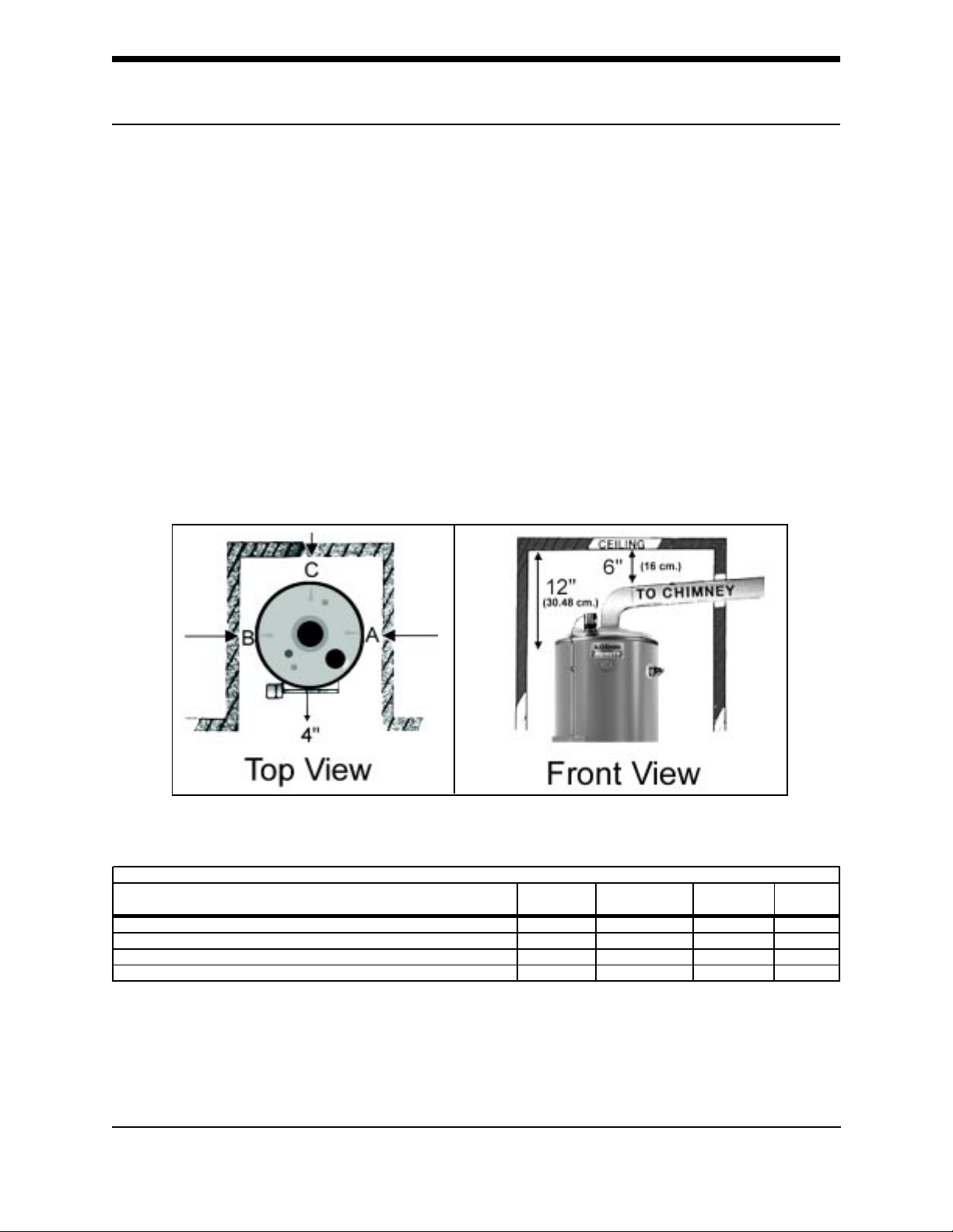
Top and Front Views of Minimum Clearances To Combustibles
Minimum Clearances To Combustibles
Model "A" Right
Side
SBN 71-120NE, SBN- 81-154NE, SBN 81-180NE, SBN 100-199NE 2" 2" 2" 12"
SBN 100-250NE(A), SBN 100-275NE(A), SBN 85-310NE(A) 3" 3" 3" 12"
SBN 85-366NE(A) 6" 6" 6" 6"
SBN 85-390NE(A) 4" 4" 4" 4"
"B" Left Side "C" Back "D"
Ceilin
A, B, and C clearances to non-combustibles is “0” inches - a 12 inch clearance to cover
remains unchanged.
©2003
4
Technical Training Department
Ashland City, Tennessee
Page 6
SBN TANK TYPE COMMERCIAL GAS WATER HEATER
SERVICE HANDBOOK
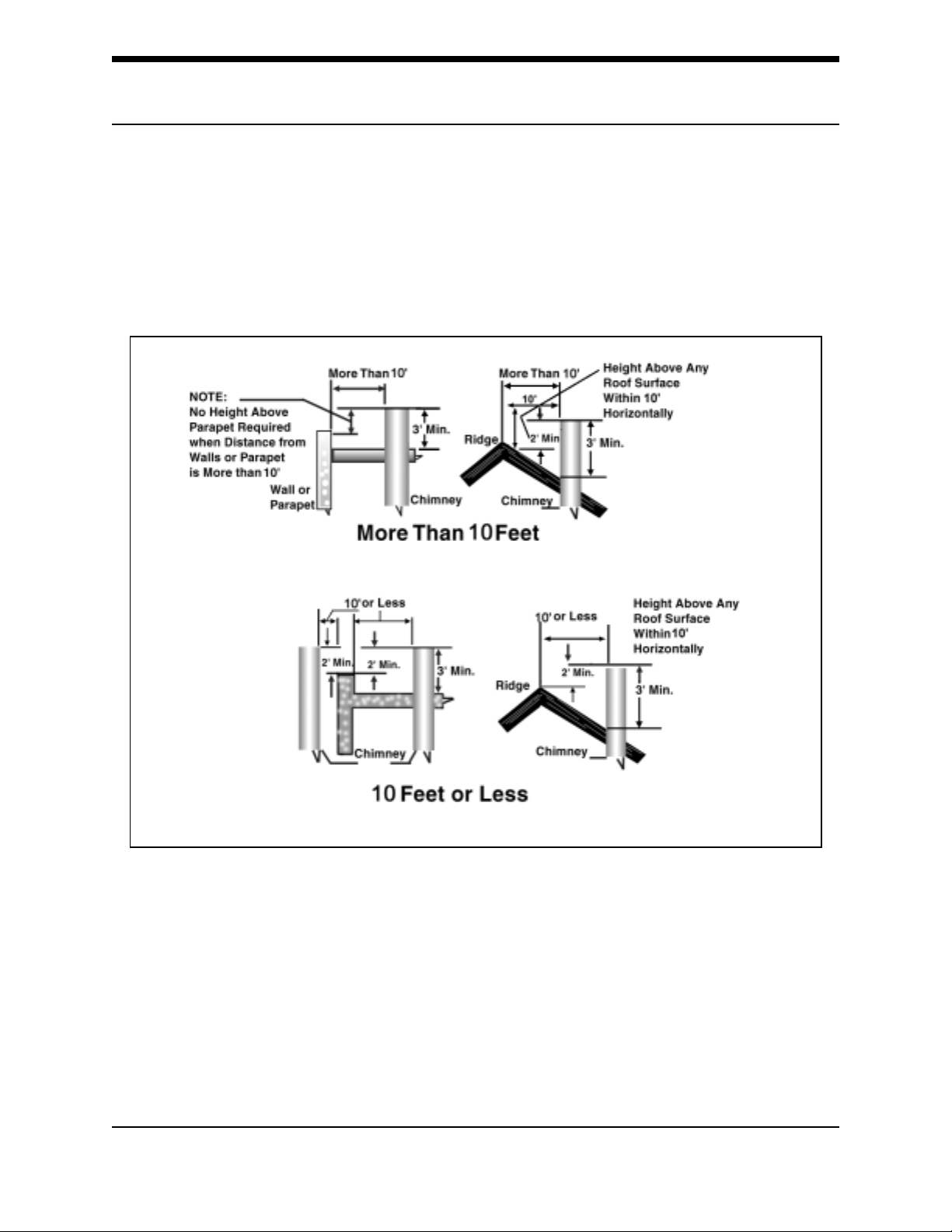
Exterior Clearance
The illustration below shows the required clearances for venting units using
natural draft venting.
Required Exterior Clearances
“Copyright by the American Gas Association. Used by permission of the copyright holder”.
The vent must extend at least 3 feet above the highest point where it passes through
a roof of a building and at least 2 feet higher than any portion of a building within a
horizontal distance of 10 feet (for vents of 12 inches in diameter or less).
References: NFPA 54 ANSI Z 223.1 SEC 7.5.2a and Sec 7.6.2a may allow reduction
to 8 feet with a “listed vent cap.”
Technical Training Department ©2003
Ashland City, Tennessee
5
Page 7
SBN TANK TYPE COMMERCIAL GAS WATER HEATER
SERVICE HANDBOOK
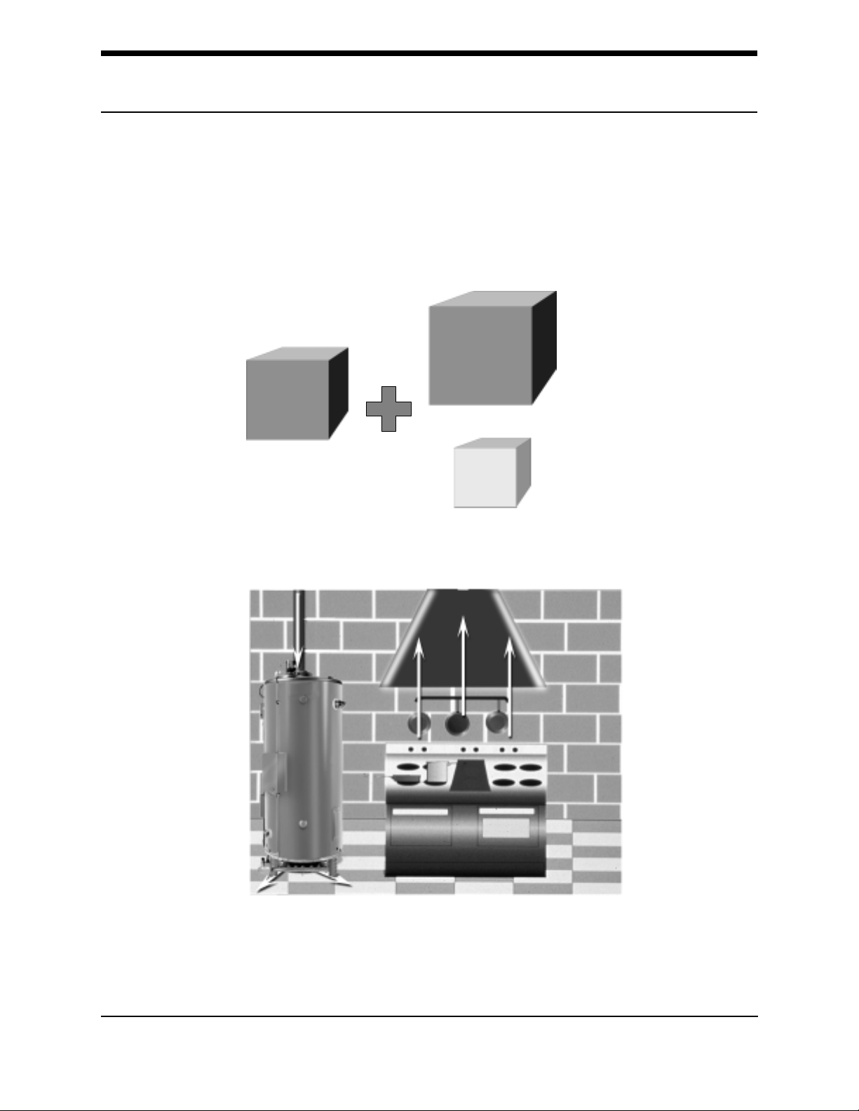
Air Supply
Stoichiometric or theoretical complete combustion requires 10 cubic feet of air per
1,000 BTUH of gas supplied. The National Fuel Gas code also recommends an
additional 2.5 cubic feet of “excess” air.
For information on minimum make-up air opening sizes for various building installations,
refer to the National Fuel Gas Code NFPA 54, ANSI Z223.1, Sec. 5.3.
10 CU.
FT.
COMB.
1,000
BTU
AIR
2.5 CU.
FT.
EXCESS
AIR
Insufficient make-up air is a major cause of combustion problems.
Insufficient Make-Up Air - Backdraft
One common example is in a restaurant installation where exhaust vent equipment was
not considered in sizing make-up requirements. This condition may result in air being
backdrafted by the restaurant exhaust equipment through the heater causing the draft
proving switch to open and/or erratic heater shutdown.
©2003
6
Technical Training Department
Ashland City, Tennessee
Page 8
SBN TANK TYPE COMMERCIAL GAS WATER HEATER
SERVICE HANDBOOK
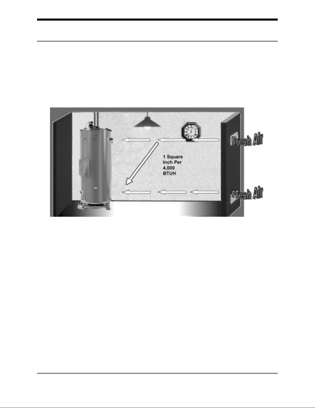
A fresh supply of make-up air for combustion can be supplied to the heater through
make-up air ducts, which directly communicate with the outdoors.
Make-Up Air – Direct Communication
(Not Direct Vent)
Two openings are required: one within 12 inches of the top of the enclosure and one
within 12 inches of the bottom of the enclosure. Each opening must have a free area
of not less than 1 square inch per 4,000 BTUH of the total input of all appliances
within the enclosure.
The lower opening primarily provides combustion air. The upper opening provides
vent dilution air and acts as a relief opening for flue gases should the vent become
obstructed or a downdraft condition occur. Additionally, when the heater is installed in
a confined space and communicating with the outdoor air, one permanent opening,
beginning within 12 inches (30 cm) of the top of the enclosure, must be permitted
where the equipment has clearances of at least 1 inch (2.5 cm) from the sides and
back, and 6 inches (16 cm) from the front of the appliance. The opening must directly
communicate with the outdoors and must communicate through a vertical or
horizontal duct to the outdoors or spaces (crawl or attic) that freely communicate with
the outdoors, and must have a minimum free area of a) 1 square inch per 3,000 BTUH
(7cm2 per kW) of the total input of all equipment located in the enclosure and b) not
less than the sum of the areas of all vent connectors in the confined space.
Technical Training Department ©2003
Ashland City, Tennessee
7
Page 9
SBN TANK TYPE COMMERCIAL GAS WATER HEATER
SERVICE HANDBOOK
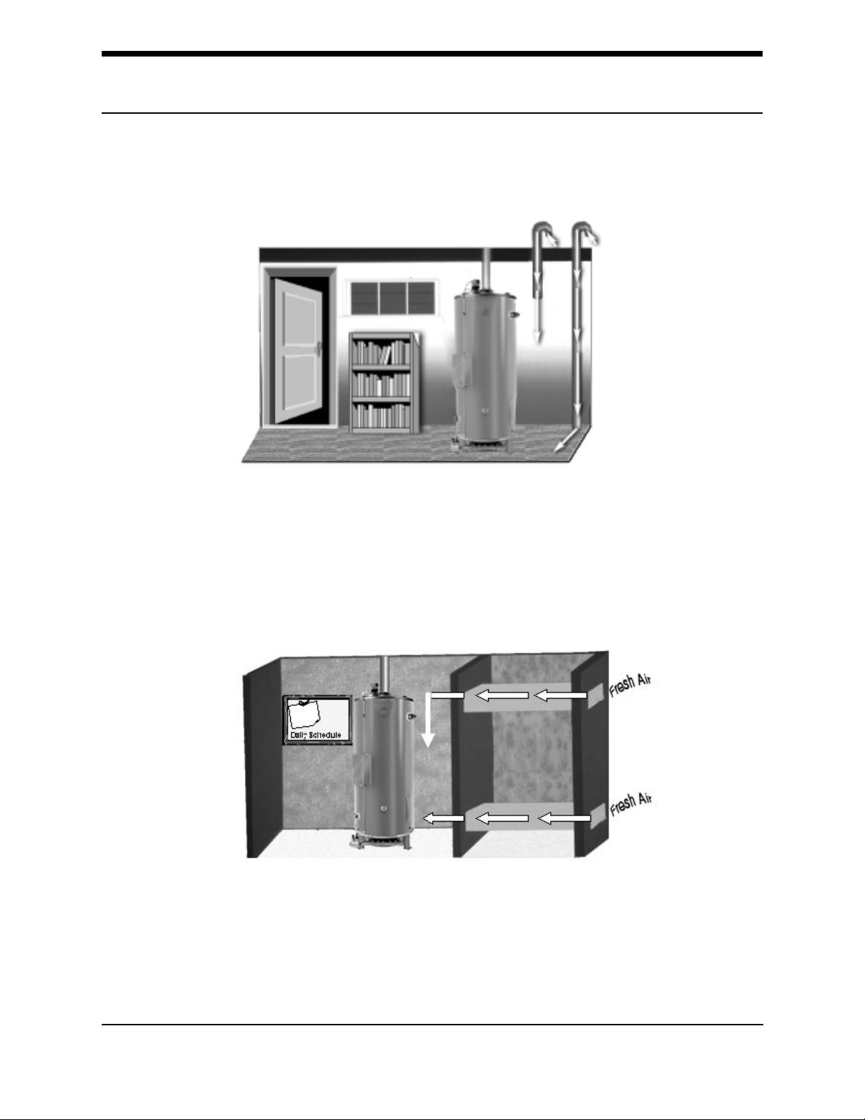
Often, it is more practical to install vertical make-up ducts to the outdoors.
Make-Up Air - Vertical Ducts
Again, two openings are required: one within 12 inches of the top of the enclosure
and one within twelve inches of the bottom of the enclosure. Each opening must
have a free area of not less than 1 square inch per 4,000 BTUH of the total input of
all appliances within the enclosure.
Make-Up Air - Horizontal Ducts
When the heater is installed in an interior room with no roof access for vertical ducts,
horizontal make-up air ducts should be installed. When using horizontal ducts, two
openings are required - one within 12 inches of the top of the enclosure and one within
12 inches of the bottom of the enclosure. Each opening must have a free area of not
less than 1 square inch per 2,000 BTUH of the total input of all appliances within the
enclosure.
©2003
8
Technical Training Department
Ashland City, Tennessee
Page 10
SBN TANK TYPE COMMERCIAL GAS WATER HEATER
SERVICE HANDBOOK
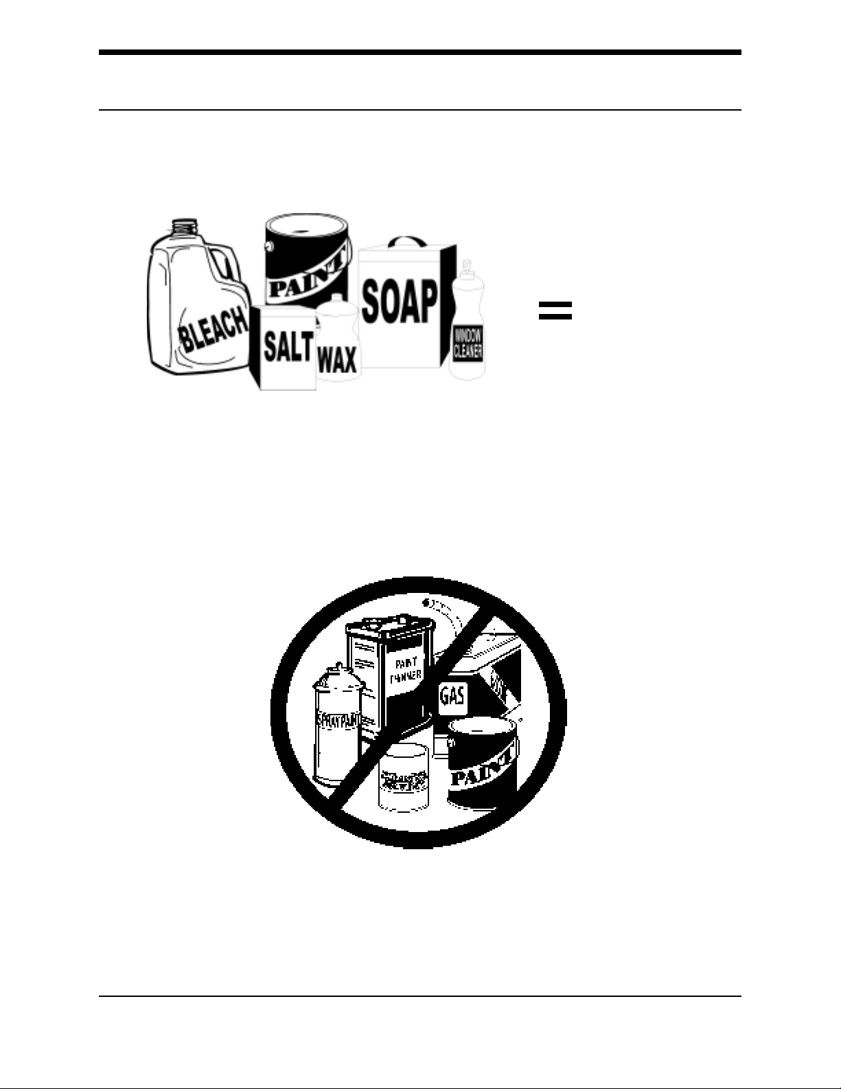
Along with adequate make-up air, the quality of the air is important.
Contaminated Air
RustRust
Rust
RustRust
ChipsChips
Chips
ChipsChips
Contaminants in combustion air can lead to premature heater failure. Vapors from
bleaches, soaps, waxes, salts, etc. are drawn into the combustion chamber with the
make-up air and, once fired, mix with water vapor in the gases to form extremely
corrosive hydrochloric or hydrofluoric acid and other corrosive by-products.
Air for Combustion – Flammable Items
Flammable items, pressurized containers or any other potentially hazardous articles
must never be placed on or adjacent to the heater. Open containers of flammable
material should not be stored or used in the same room with the heater.
Technical Training Department ©2003
Ashland City, Tennessee
9
Page 11
SBN TANK TYPE COMMERCIAL GAS WATER HEATER
SERVICE HANDBOOK
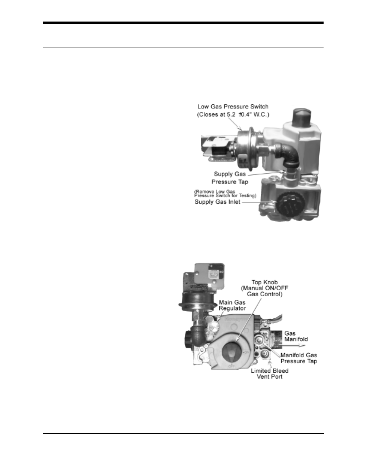
The supply gas pressure is
normally measured at the gas
valve inlet gas pressure tap,
if available, when the gas is flowing.
The manifold gas pressure
is measured at the manifold
pressure tap of the gas valve
when the gas is flowing.
Gas valves used are 24 volt AC
combination-step opening gas
valves. They incorporate the
main valve and gas pressure
regulator into one body. The
Low Gas Pressure Switch, the
Supply Gas Inlet, and the
Supply Gas Pressure Tap are
shown in the Inlet View to the
right.
Gas Valve
Inlet View
Top View
The top view of the gas valve,
shown on the right, shows the
Main Gas Regulator, Manifold
Pressure Tap, Top Knob, and the
Limited Bleed Vent Port. The main
gas regulator is found under the
silver cap screw. It is factory preset
to 3.5 inches W.C. and
adjusts gas pressure output
from 3.0 to 5 inches water
column. Caution: Always test
the manifold pressure at the
outlet when the gas is flowing.
©2003
10
Technical Training Department
Ashland City, Tennessee
Page 12
SBN TANK TYPE COMMERCIAL GAS WATER HEATER
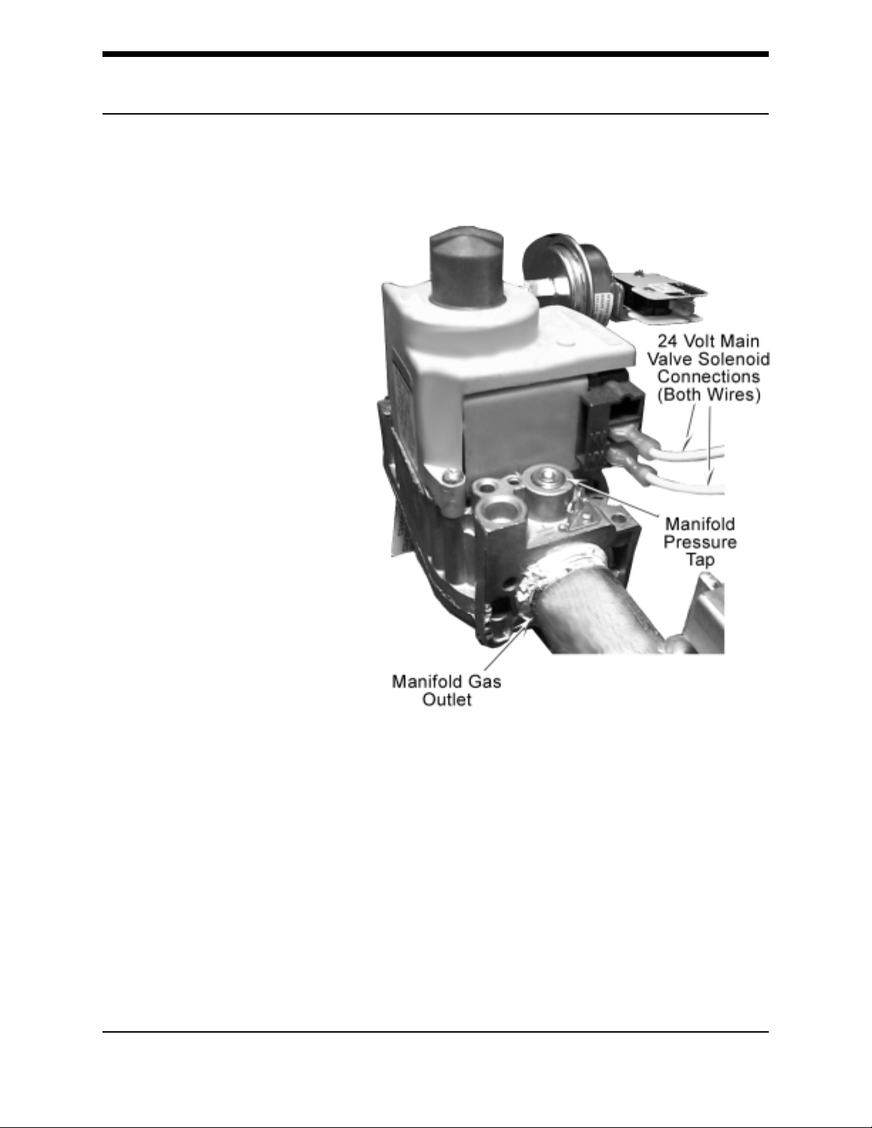
The outlet view of the Gas
Valve, shown on the right,
shows the Manifold Gas
Outlet Connection, the two
24 volt Main Valve (MV)
Solenoid connections, and
the Manifold Pressure Tap.
The two yellow wires from
the 12-pin plug on the
Ignition Board attach to the
MV terminals.
SERVICE HANDBOOK
Outlet View
Technical Training Department ©2003
Ashland City, Tennessee
11
Page 13
SBN TANK TYPE COMMERCIAL GAS WATER HEATER
SERVICE HANDBOOK
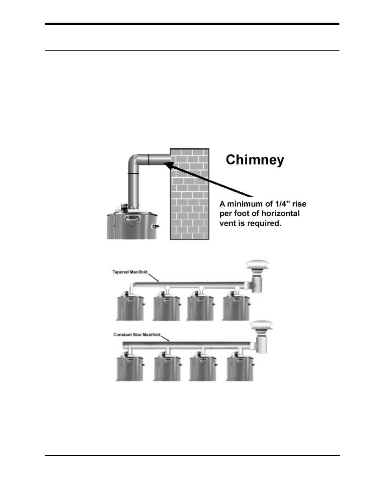
Venting
All SBN water heaters are classified by ANSI as Category I (non-condensing,
negative pressure venting) appliances. They are approved for type B vent. The draft
inducer does not pressurize the exhaust.
Venting – Atmospheric Multiple Heaters
For larger applications, SBN water heaters can be common vented together,
either in a tapered manifold or constant size manifold. Follow the National Fuel Gas
Codes requirements for sizing and installation of fan-assisted products.
SBN Models may be common vented only with other Category I appliances. See the
Venting Section in the National Fuel Gas Code.
©2003
12
Technical Training Department
Ashland City, Tennessee
Page 14
SBN TANK TYPE COMMERCIAL GAS WATER HEATER
A
A
SERVICE HANDBOOK
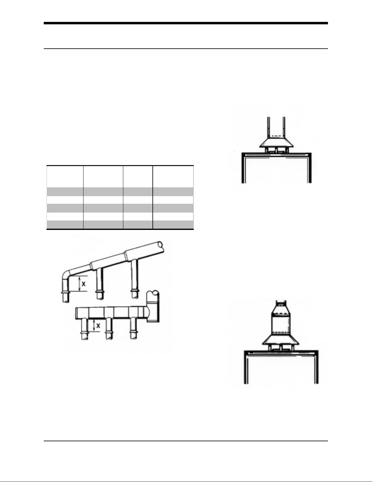
When vents are combined, the area of the combined vent should be equal to area of the largewst
single vent, plus 50% of area of all others joining.
EXAMPLE: To combine two 6” vents with
an 8” vent, the area of a
combined vent should be
one half area of two 6 inch
vents (14 + 14) plus area of 8 inch vent (50)
or 78 sq. inches. Referring to char, 78
sq. inches require 10” diameter vent.
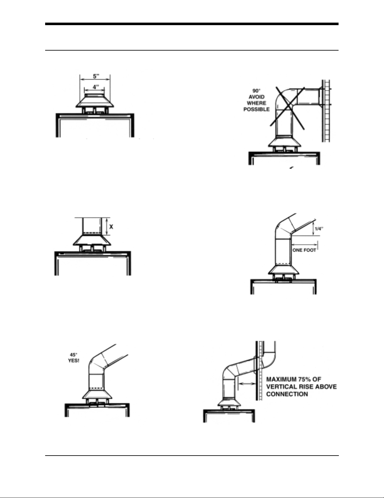
NINE RULES FOR
GOOD VENTS
rea in
Vent Size
5" 20 10" 79
6" 28 12" 113
7" 38 14" 154
8" 50 16" 201
9" 64 18" 254
Square Inches Vent Si ze
rea in
Square Inches
1. The vent pipe should ALWAYS
be the same size as the outlet of
the draft diverter or factory
supplied vent reducer.
• Model SBN 120 are
supplied with a 6” to 5”
reducer.
• Models SBD 250, 251
and 275 are supplied
with a 8” to 6” reducer.
2. The diameter of a vent pipe
should NEVER be reduced, no
matter what the circumstances.
Technical Training Department ©2003
Ashland City, Tennessee
13
Page 15
SBN TANK TYPE COMMERCIAL GAS WATER HEATER
3. In some cases it may be
necessary to run a vent larger
than the draft diverter outlet.
SERVICE HANDBOOK
4. Take the maximum vertical
rise possible immediately
above the draft diverter.
5.
©2003
6. Horizontal pipe should be sloped
upward at a minimum of ¼” per foot.
7. Horizontal elements should be limited to
75% of the vertical rise of the vent above
the connection.
14
Technical Training Department
Ashland City, Tennessee
Page 16

SBN TANK TYPE COMMERCIAL GAS WATER HEATER
SERVICE HANDBOOK
8. Flue gases must be kept hot for
proper venting.
9. Obstructions can cause down
drafts.
The vent pipe should be extended to
meet local codes.
Technical Training Department ©2003
Ashland City, Tennessee
15
Page 17

SBN TANK TYPE COMMERCIAL GAS WATER HEATER
SERVICE HANDBOOK
TYPE B GAS VENT
Multiple Gas Fired Tank-Type Heaters
When venting multiple tank type heaters using Type
B vent pipe, follow the installation diagram (figure 4) and
tables below which give sizing and data based upon NFPA
54/ANSI Z223. 1992.
MODEL SBN 71-120NE
Input: 120,000 Btu/hr Total Vent Height (Feet)
Vent Connector Size: 5 inches 6 8 10 15 20 30 50 100
Number of Combined Input
Heaters in Thousands of Btu/hr Manifold and Common Vent Diameter (Inches)
2 240,000 7 7 6 6 6 6 6 6
3 360,000 8 8 7 7 7 6 6 6
4 480,000 9 9 9 8 8 7 7 6
MODEL SBN 81-154NE
Input: 154,000 Btu/hr Total Vent Height (Feet)
Vent Connector Size: 6 inches 6 8 10 15 20 30 50 100
Number of Combined Input
Heaters in Thousands of Btu/hr Manifold and Common Vent Diameter (Inches)
2 308,000 7 7 6 6 6 6 6 6
3 462,000 8 8 7 7 7 6 6 6
4 616,000 9 9 9 8 8 7 7 6
MODEL SBN 81-180NE, SBN 100-199NE
Input: 180,000, 190,000 and 199,000 Btu/hr Total Vent Height (Feet)
Vent Connector Size: 6 inches 6 8 10 15 20 30 50 100
Number of Combined Input
Heaters in Thousands of Btu/hr Manifold & Common Vent Diameter (Inches)
2 380,000 7 7 7 6 6 6 6 6
3 570,000 7 6 6 6 6 6 6 6
4 760,000 6 6 6 6 6 6 6 6
Input Btu/hr Rise Vent Connector Diameter (Inches)
120,000 1 Ft. 6 6 5 5 5 5 5 5
120,000 2 Ft. 5 5 5 5 5 5 5 5
120,000 3 Ft. 5 5 5 5 5 5 5 5
Input Btu/hr Rise Vent Connector Diameter (Inches)
154,000 1 Ft. 6 6 6 6 6 6 6 6
154,000 2 Ft. 6 6 6 6 6 6 6 6
154,000 3 Ft. 6 6 6 6 6 6 6 6
Input Btuh/hr Rise Vent Connector Diameter (Inches)
180,000 1 Ft. 7 7 6 6 6 6 6 6
190,000 1 Ft. 7 7 7 6 6 6 6 6
199,000 1 Ft. 7 7 7 6 6 6 6 6
180,000 2 Ft. 6 6 6 6 6 6 6 6
190,000 2 Ft. 7 6 6 6 6 6 6 6
199,000 2 Ft. 7 7 6 6 6 6 6 6
180,000 3 Ft. 6 6 6 6 6 6 6 6
190,000 3 Ft. 6 6 6 6 6 6 6 6
199,000 3 Ft. 6 6 6 6 6 6 6 6
360,000 7 7 6 6 6 6 6 6
398,000 6 7 7 6 6 6 6 6
540,000 7 6 6 6 6 6 6 6
597,000 6 7 6 6 6 6 6 6
720,000 6 6 6 6 6 6 6 6
796,000 6 6 6 6 6 6 6 6
©2003
16
Technical Training Department
Ashland City, Tennessee
Page 18

SBN TANK TYPE COMMERCIAL GAS WATER HEATER
SERVICE HANDBOOK
MODEL SBN 100-250NE TECHNICAL DA T A VENTING (Continued)
Input: 250,000 Btu/hr Total Vent Height (Feet)
Vent Connector Size: 6 inches 6 8 10 15 20 30 50 100
Number Combined Input
of Heaters in Thousands of Btu/hr Manifold and Common Vent Diameter (Inches)
2 500,000 9 9 9 8 8 7 7 7
3 750,000 12 12 10 10 10 9 8 8
4 1,000,000 14 14 12 12 10 10 9 9
MODEL SBN 100-275NE
Input: 275,000 Btu/hr Total Vent Height (Feet)
Vent Connector Size: 6 inches 6 8 10 15 20 30 50 100
Number of Combined Input
Heaters in Thousands of Btu/hr Manifold and Common Vent Diameter (Inches)
2 550,000 10 9 9 8 8 8 7 7
3 825,000 12 12 12 10 9 9 8 8
4 1,100,000 14 14 14 12 12 10 9 9
MODEL SBN 85-310
Input: 310,000 Btu/hr Total Vent Height (Feet)
Vent Connector Size: 6 inches 6 8 10 15 20 30 50 100
Number of Combined Input
Heaters in Thousands of Btu/hr Manifold & Common Vent Diameter
2 620,000 10 10 9 9 8 8 7 7
3 930,000 14 12 12 12 10 9 9 8
4 1,240,000 14 14 14 12 12 12 10 9
MODEL SBN 85-366NE, SBN 85-390NE
Input: 366,000, 399,000 Btu/hr Total Vent Height (Feet)
Vent Connector Size: 6 inches 6 8 10 15 20 30 50 100
Number of Combined Input
Heaters in Thousands of Btu/hr Manifold & Common Vent Diameter (Inches)
2 732,000 12 10 10 9 9 9 8 8
3 1,098,000 14 14 14 12 12 10 9 9
4 1,464,000 16 16 14 14 14 12 12 10
Input Btuh/hr Rise Vent Connector Diameter (Inches)
250,000 1 Ft 8 8 7 7 7 6 6 6
250,000 2 Ft 7 7 7 7 6 6 6 6
250,000 3 Ft 7 7 7 7 6 6 6 6
Input Btu/hr Rise Vent Connector Diameter (Inches)
275,000 1 Ft 8 8 7 7 6 6 6 6
275,000 2 Ft. 8 8 7 7 6 6 6 6
275,000 3 Ft 7 7 7 7 6 6 6 6
Input Btu/hr Rise Vent Connector Diameter (Inches)
310,000 1 Ft. 9 8 8 8 7 7 6 6
310,000 2 Ft. 8 8 8 7 7 7 6 6
310,000 3 Ft. 8 8 8 7 7 7 6 6
Input Btu/hr Rise Vent Connector Diameter (Inches)
366,000 1 Ft 9 9 9 8 8 8 8 8
399,000 1 Ft 10 9 9 9 8 8 8 8
366,000 2 Ft 9 9 8 8 8 8 8 8
399,000 2 Ft 9 9 9 8 8 8 8 8
366,000 3 Ft 9 8 8 8 8 8 8 8
399,000 3 Ft 9 9 8 8 8 8 8 8
798,000 12 12 10 10 9 9 8 8
1,197,000 14 14 14 12 12 10 10 9
1,596,000 16 16 16 14 14 12 12 10
Technical Training Department ©2003
Ashland City, Tennessee
17
Page 19

SBN TANK TYPE COMMERCIAL GAS WATER HEATER
(-)
(-)
(-)
SBN SEQUENCE OF OPERATION
Sequence
1. Thermistors (probes) call for
heat.
2. Inducer fan starts and
provides draft.
3. Hot surface igniter = 20 sec.
warmup.
4. Main gas valve opens 4 sec.
trial for ignition. (Maximum 5
trials.)
5. Main burner ignites and
proves.
6. Thermistors reach the
temperature setting.
7. Main burners “OFF”
- Auto restart after 60 min.
- 20 sec blower “interpurge”
between trials
SERVICE HANDBOOK
©2003
Top View
Draft Proving (Pressure) Switch Table
SBN Models Part No.
366 194411-0
275 194411-1
310 194411-2
120, 199, 250,
400
154, 180, 199 194411-4 (-) 2.60" ± .10"
18
194411-3 (-) 2.40" ± .10"
Technical Training Department
Ashland City, Tennessee
Pressure Setting To
Close Switch (Inches
W.C.)
1.60 ± .10"
2.00" ± .10"
1,75" ± .10"
Page 20

SBN TANK TYPE COMMERCIAL GAS WATER HEATER
SERVICE HANDBOOK
FRONT VIEW OF WATER HEATER
Technical Training Department ©2003
Ashland City, Tennessee
19
Page 21

SBN TANK TYPE COMMERCIAL GAS WATER HEATER
SERVICE HANDBOOK
WHITE ROGERS INTEGRA TED WA TER HEA TER CONTR OL
(PART NO . 194393-0) - ALSO CALLED “THERMOSA T”
©2003
20
Technical Training Department
Ashland City, Tennessee
Page 22

SBN TANK TYPE COMMERCIAL GAS WATER HEATER
SERVICE HANDBOOK
HSI INTEGRATED IGNITION CONTROL BOARD
(PART NO. 194392)
E4
E1
Technical Training Department ©2003
Ashland City, Tennessee
21
Page 23

SBN TANK TYPE COMMERCIAL GAS WATER HEATER
SERVICE HANDBOOK
LOWER FRONT VIEW OF SBN WATER HEATER
©2003
Notice that rods cross
main burner flame
.1 - .25”
HSI
Part Number 194405
Volts AC Nominal 80 VAC
Ohms Resistance 11.0 - 20.0 @ 77° F (25° C)
22
Technical Training Department
Ashland City, Tennessee
Page 24

SBN TANK TYPE COMMERCIAL GAS WATER HEATER
SERVICE HANDBOOK
WIRING DIAGRAM
R
Upper ECO
{}
B
RB
Propane (series) models do not have a low gas presure switch.
Technical Training Department ©2003
Ashland City, Tennessee
23
Page 25

SBN TANK TYPE COMMERCIAL GAS WATER HEATER
SERVICE HANDBOOK
ELECTRICAL SEQUENCE OF SBN WA TER HEA TER OPERA TION
120 VAC
Power to Heater
Green LED - On
Call for Heat
Green LED - On
Module Self Check
Closes -1.6 to -2.60 ± .10 W.C. depending on heater model
Variable Voltage
(80-120 VAC)
Low Gas Pressure
Switch is Closed
Draft Proving Switch
Is Open
High Limit is Closed
Inducer On
Blower Prover
Ignition Control Board –
120 VAC
HSI Warm Up
20 seconds
Gas Valve Open 3 Second Trial
HSI - Off
3 Seconds to Prove
Flame After HSI - Off
Flame Proves
Natural Gas Models Only
Minimum Millivolt for
4.25 seconds
©2003
Yes
Tank Heated to Set Temperature
Gas Valve – Off
Call for Heat LED - Off
60 Second Blower Post Purge
Blower Prover - Opens
Standby LED - On
No
20 Second Blower Purge
2 More Trials
To Prove Flame
Yes
Flash 8 Times On Diagnostic LED
Lock Out for 1 Hour
Yes
No
Then Retry
24
No
Flash 7 Times
1 Hour Auto Reset
Technical Training Department
Ashland City, Tennessee
Page 26

SBN TANK TYPE COMMERCIAL GAS WATER HEATER
SERVICE HANDBOOK
PRE-SER VICE CHECKLIST
Use the following chec klist BEFORE y ou begin servicing the water heater.
1. Have you removed the cover from the controls?
____________________________________________________
Did you take notice of the status lights on the upper water
heater control?
____________________________________________________
Did you take notice of the red LED in the upper left corner of
the lower ignition control?
____________________________________________________
2. Did you note conditions of the room?
____________________________________________________
Where does the supply air come from?
____________________________________________________
Is the room clean?
____________________________________________________
What is stored with the heater?
____________________________________________________
How is the heater vented?
____________________________________________________
Are all water and gas shut-off valves open?
____________________________________________________
Are there room exhaust or air intake fans?
____________________________________________________
3. Did you note the condition of the water heater?
____________________________________________________
Is the ON/OFF switch “On”?
____________________________________________________
What is the temperature of the stored water? (T est at T&P valve
or nearby faucet.)
____________________________________________________
Is the thermal expansion tank installed?
____________________________________________________
4. Did you write down the complete model and serial numbers of
the water heater? If so, what are they?
____________________________________________________
5. Does the water heater have a good ground wire connection? If
not, the inducer will typically come on for a short time (3-5
seconds), then go off, and the red LED will flash 8 times.
Yes / No
Yes / No
Yes / No
Yes / No
Yes / No
Yes / No
Yes / No
Yes / No
Yes / No
Yes / No
Yes / No
Yes / No
Yes / No
Yes / No
Yes / No
Technical Training Department ©2003
Ashland City, Tennessee
25
Page 27

SBN TANK TYPE COMMERCIAL GAS WATER HEATER
p
SERVICE HANDBOOK
CONTROL BOARD DIAGNOSTIC LED INTERPRETATION AND
TROUBLESHOOTING
TEST 1 - 120 VAC CHECK TO WATER HEATER
Conditions:
No Green display “Power” LED on.
Plugs are in receptacles.
Supply power breaker is not “open”
On/Off heater switch is “On”.
Ignition Control
Board
Water Heater
Control
120 Vac Check To Water Heater On Switch
TEST 1
Check for 115-125 VAC black wire to ground
115 V check to E13 terminal and 2B receptical.
If… ...then
voltage
center black wire to ground
power
terminal
voltage
power
voltage
receptacle E2 black to ground
power is
©2003
is not present
is present
is not present
is present
is not present
resent
from on/off switch-
from center on/off
at E13 to ground
at E13
from heater control
at E2 green LED should be on.
check conditions above
check wiring from switch to break box
check power from on/off to ignition board term
E13.
check wiring from on/off. Left-outside terminal
to E13.
replace on/off switch.
check power from E14 to heater control E2
receptacle
check wiring from ignition control board E14 to
heater control receptacle E2.
replace ignition control board.
26
Technical Training Department
Ashland City, Tennessee
Page 28

SBN TANK TYPE COMMERCIAL GAS WATER HEATER
SERVICE HANDBOOK
FLASH CODES OF DIAGNOSTIC INDICATOR
Conditions:
Power On
Red, heater control “Call for Heat” LED – on
Red, ignition control board diagnostic LED – Flashing
Note LED Flash Code before resetting heater.
LED Status Indication
1 Flash System is in lo ck out.
2 Flashes Draft proving (pressure) switch failed to open within 5 seconds at the end of the last cycle.
3 Flashes Draft proving (pressure) switch failed to close ( -2.1 inches of water column pressure) within 5
seconds after the inducer was started.
The low gas pressure switch )closes at 5.2" ± .04" w.c.) may have remained open.
4 Flashes Open on high temperature limit switch (ECO).
6 Flashes 115-volt supply power connection is indicating reversed polarity.
7 Flashes Flame sensor reads a low flame signal for more than 4.25 sec.
8 Flashes No ignition sensed.
Continuous Flash Continuous flame sensed for more than 5 seconds without gas valve being energized.
Continuous ON Internal control board failure.
*Control system self adjusts to use a minimum voltage for ignition. Lower voltage results in lower igniter temperature
which results in longer igniter life. Igniter voltage may vary from Nominal 80 VAC.
TEST 2 - POLARITY CHECK
Conditions:
No hot water
Green “Power” LED is on.
Tank is more than 5° F
below temperature dial
setting.
Red ignition control board
diagnostic LED is flashing
6 times between pauses.
Red, diagnostic “Call for
Heat” LED-OFF.
Display
LED’s
Continued on next page
Technical Training Department ©2003
Ashland City, Tennessee
27
Page 29

SBN TANK TYPE COMMERCIAL GAS WATER HEATER
p
g
SERVICE HANDBOOK
TEST 2 - POLARITY CHECK - continued
Polarity Check
TEST 2
Check from on/off switch center and white wire terminals to ground
If… ...then
115-125 VAC
voltage
ground
round
is present
but not
is not
black (center terminal) to
resent
white (right terminal) to
see Test 1.
reverse supply wire connections - polarity is
reversed.
TEST 3 - CONTINUITY CHECK
OF HIGH LIMIT (ECO)
Conditions:
Power On – No Hot Water
Red, heater control “Call for Heat”
LED – on
Red, ignition control board
diagnostic LED – 4 Flashing
Note LED Flash Code before
resetting heater.
See Description of diagnostic
LED Flashes.
Turn Power “Off”
Continued on next page
©2003
28
Technical Training Department
Ashland City, Tennessee
Page 30

SBN TANK TYPE COMMERCIAL GAS WATER HEATER
y
SERVICE HANDBOOK
TEST 3 - CONTINUITY CHECK OF HIGH LIMIT (ECO)-CONTINUED
TEST 3
Continuity check of ECO (energy cut-off, high limit)
Black to Black wires of upper probe. Power is off.
If… ...then
continuity
continuity
water is less than 120° F
is indicated
is not present
opens at 203° F; closes at 193° F. If water is
below 193° F, continuity is correct.
replace ECO sensor, if water temperature is
below 193° F.
•
reset status LED should be on.
•
replace heater control if control will not manually
reset.
TEST 4 - UPPER TEMPERATURE PROBE CONTINUITY CHECK
Conditions:
Power On - Water below tempera-
ture set point.
Red, heater control “Reset Status”
LED-OFF
“Call For Heat” LED off.
Ohms Resistance Table
° F Ohms
70° 11,884
120° 3,759
140° 2,488
180° 1,169
TEST 4
Upper Temperature probe continuity check
Red wire to red wire - Turn supply power "Off" for this test
If… ...then
test indicates
continuity
Technical Training Department ©2003
Ashland City, Tennessee
no continuit
is indicated
replace probe.
probe should be okay (also verify Ohms
resistance for water temperature). (Reading will
be approximate.)
29
Page 31

SBN TANK TYPE COMMERCIAL GAS WATER HEATER
g
g
SERVICE HANDBOOK
TEST 5 - CALLING FOR HEAT – NO
INDUCER OPERATION
Conditions:
Power on
Plugs in Receptacles
Red “ Call for Heat” LED-ON
Inducer “Off”
Note flash code on ignition control board
diagnostic LED
Diagnostic
LED
Water Heater
Control
Display
LED’s
Ignition Control Board
E4
TEST 5
115-120 V Check to Inducer
Test on Ignition Board 4 Pin Receptacle E4
If… ...then
•
reset control by interrupting power - note
pin 1 to ground check
pin 1 to ground
pin 3 to ground
©2003
has volta
has no voltage
has no voltage
e
possible reasons for this from flashing LED code
•
replace i
proceed
•
check wiring harness and plugs
•
replace inducer
30
ntion board
Technical Training Department
Ashland City, Tennessee
Page 32

SBN TANK TYPE COMMERCIAL GAS WATER HEATER
SERVICE HANDBOOK
TEST 6 - INDUCER ON-NO IGNITION
Conditions:
Power on
Plugs in receptacles
Inducer operating
No power to Hot Surface Igniter (HSI)
Note flash code of LED
Draft Exhaust
Draft Proving Pressure
Switch
Low Gas
Pressure
Switch
24 VAC Check of Blower Prover/Low Gas Pressure Circuit
TEST 6
If… ...then
igntion board receptacles E1, Pin 7 to ground
no volta ge
E1, Pin 7
voltage check of each blower switch terminal to
ground
24V
has 24 Volt
sho w s vol ta ge
is present
from eac h switch terminal to ground.
to ground check wire connection to and from inducer
to only 1 terminal
sh o w s
replace Ignition board
switch is open - check for proper draft (should
•
also s ee LED 3 flash code)
chec k for blocked exhaust
•
chec k that blower outlet exhaust damper is open
•
replace blower (draft) proving switch
•
check wiring from blower switch to low gas
•
pressure switch
Optional Hot
Water Outlet
Exhaust
Outlet
Inducer
voltage check to each terminal of low gas pressure
switch and ground
term i nal
voltage
and ground
Technical Training Department ©2003
Ashland City, Tennessee
is present
show s only voltage on 1
to each pressure switch terminal
switch is open - test for a minimum of 5.2 ± "
•
W.C. Natural Gas or 10.5" Propane, flowing
supply gas pressure (should also see 3 Flash
LED code)
replace low gas pressure switch
•
check wiring from low gas pressure switch to
ignition board recetacles E1, Pin 10
31
Page 33

SBN TANK TYPE COMMERCIAL GAS WATER HEATER
g
p
g
SERVICE HANDBOOK
TEST 7 - INDUCER ON – PROVER SWITCH AND LOW GAS SWITCH
CLOSED – NO IGNITER OPERATION
Conditions:
Power on
Plugs in receptacles
Inducer on
24V at ignition board
E1, Pin 10
No Power to igniter
Note: Flash code of LED
Check E4 pin 4 to Ground
Continuity Test
E4 Plug
Check E1 pin 10
24V
Voltage check and continuity check of hot surface igniter circuit
TEST 7
Continuity check - Power off- Plug removed from E4 receptacles
Nominal 80 VAC check - Plug in E4- Power "On"
If… ...then
continuity
plug pin 2 to 4.
continuity
voltage is not present
to ground
volta
voltage
to
round
voltage
is not indicated
is present
e
is
resent
is not present
is present
between E4
between E4, Pin 2
between E4, Pin 4
check wiring and connection from E4 plug to
HSI receiving plug
replace HSI Assembly
resistance should be between 11 and 20 Ohms
at a temperature of 77°F
replace ignition board
continue
check wiring and plug connections to HSI
replace HSI
note igntion board, Flash code LED
HSI should work
Check E4 pin 2 to Ground
©2003
32
Technical Training Department
Ashland City, Tennessee
Page 34

SBN TANK TYPE COMMERCIAL GAS WATER HEATER
SERVICE HANDBOOK
TEST 8 - IGNITER HEATS – NO MAIN BURNER
Conditions:
Plugs in receptacle
Igniter energizes (gets red)
No main burner or main shuts off within 5 seconds.
Note flash code of LED.
Pin 9
24
E1 Plug, Pin 9
Plug in Receptacle
Test of Igniter and gas valve circuit
TEST 8
If… ...then
short heat up time of igniter
normal (Approximate 20 seconds)
warm up - no ignition
no voltage present
ground
24 Volt
12 to ground, but no main burner
was present
E4, Pin 12 to
from E1, Pin
•
check control box grounding
•
check for 24V from E1, Pin 12 to ground during 4
second trial.
- Yes - Continue
- No - Replace Igntion Board
replace ignition board
•
check that air has been purged from gas circuit
•
check that wiring and connections to gas valve and
E1, Pin 9 are correct
•
check for 24 VAC at E1, Pin 9 to ground during 4
second trial
Pin 12
24
E1 Plug, Pin 12
Plug in Receptacle
Technical Training Department ©2003
Ashland City, Tennessee
33
Page 35

SBN TANK TYPE COMMERCIAL GAS WATER HEATER
TEST 9 - IGNITER HEATS – NO MAIN BURNER
Conditions:
Test 8 completed then:
Turn off power
Disconnect wires from gas valves
SERVICE HANDBOOK
TEST 9
Continuity Check Of Gas Valve Coil
If… ...then
check meter scale setting to read between 550
meter reads 0 or 1
meter indicates pilot and main coil
continuity
©2003
have
and 650 Ohms
replace Gas Valve
valve should be okay
still no gas to main burner, then coil may be
stuck - Replace Valve
34
Technical Training Department
Ashland City, Tennessee
Page 36

SBN TANK TYPE COMMERCIAL GAS WATER HEATER
SERVICE HANDBOOK
TEST 10 - MAIN BURNER IGNITION FOR LESS THAN 5 SECONDS
Conditions:
Power On – plug connected
Main Burner ignites for approximately 5 seconds then goes out.
Tests 8 and 9 completed
Note flash code on ignition board LED.
Hot Surface Igniter
Pin 2
E1, Pin 2 - From Flame Proving Rod
TEST 10
Flame Prover Circuit Check
If… ...then
no extended
main burner igntion
check wiring and plug connections of HSI assembly
plug and ignition board receptacles E1, Pin 2
check that HSI assembly is not cracked or dirty
check that flame prover will be in main flame
replace HSI assembly
Main Burner
(Illustration of low NOx burner)
still no extended
Technical Training Department ©2003
Ashland City, Tennessee
main burner ignition replace ignition control board
35
Page 37

SBN TANK TYPE COMMERCIAL GAS WATER HEATER
SERVICE HANDBOOK
TEST 11 - WATER HEATER SHUTTING OFF BELOW SETTING
Conditions:
Main burner ignited
Stored water is below temperature setting more than 5° F (Tank Average).
Power off
Plug disconnected from heater control board receptacle E3 and E4
Red
Black
Red
Water Temperature Circuit Check - Continuity
TEST 11
If… ...then
continuity check pin to pin of lower
temperature probe shows 1 or 0 (E4)
continuity check red wire pin to red wire pin
on upper temperature sensor shows 1 or 0
(E3)
all above checks are okay replace the water heater control.
see Test 4
check wiring and plug connections to heater
control board receptacle E4
replace lower temperature probe
see Test 4
check wiring and plug connections to heater
control board receptacle
replace upper temperature probe
©2003
36
Technical Training Department
Ashland City, Tennessee
Page 38

SBN TANK TYPE COMMERCIAL GAS WATER HEATER
SERVICE HANDBOOK
DISPLAY LIGHTS ON INTEGRATED HEATER CONTROL
Red
Green
Red
Calling for heat
Calling for heat
The ECO (Energy Cut
The ECO (Energy Cut
Off) has opened.
Off) has opened.
Red
Action to be TakenIndicationLED Status
Action to be TakenIndicationLED Status
Normal status –
Normal status –
none
none
•Check for
•Check for
excessively hot
excessively hot
water (203° F or
water (203° F or
higher).
higher).
•Correct the
•Correct the
problem
problem
Check the breaker.No power
Check the breaker.No power
Tank is at a set
Tank is at a set
temperature of ± 2° F.
temperature of ± 2° F.
Tank has cooled
Tank has cooled
below 120° F
below 120° F
Preceded by “ECO
Preceded by “ECO
Open” indication
Open” indication
Technical Training Department ©2003
Ashland City, Tennessee
37
•Push the manual
•Push the manual
reset button.
reset button.
•Troubleshoot for
•Troubleshoot for
“why” the ECO
“why” the ECO
opened
opened
Page 39

SBN TANK TYPE COMMERCIAL GAS WATER HEATER
SERVICE HANDBOOK
LED INDICATORS ON HOT SURFACE IGNITION (HSI)
USING FLASHING RED LED ON HSI (HOT SURFACE IGNITION)
LED STATUS INDICATION ACTION TO BE TAKEN
1 Flash
2 Flashes
3 Flashes
System is in lockout.
Draft proving
(pressure) switch
(closes at -2.10 +0.01
inches W.C. negative
pressure) failed to
open within 5 seconds
at the end of the last
cycle.
Draft proving
(pressure) switch
failed to close
within 5 seconds after
the inducer was
started.
Interrupt power to
reset. Heater had not
sensed the flame –
check gas supply and
igniter condition.
Test for defective
switch or a
pressurized room
condition that may be
forcing air through the
inducer.
Check the draft.
The low gas pressure
switch closes at 5.2 inches W.C.
may have remained open.
Verify the supply gas pressure
while the gas is flowing.
4 Flashes
6 Flashes
©2003
Open on high
temperature
limit switch
(ECO)
115-volt supply power
connection is
indicating reversed
polarity.
38
Check temperature
control operation.
Verify that a neutral-to-ground
check results
in “0” volts and a hot-toground check
results in 115-125 VAC.
Technical Training Department
Ashland City, Tennessee
Page 40

SBN TANK TYPE COMMERCIAL GAS WATER HEATER
SERVICE HANDBOOK
LED INDICATORS ON HOT SURFACE IGNITION (HSI)
USING FLASHING RED LED ON HSI (HOT SURFACE IGNITION)
LED STATUS INDICATION ACTION TO BE TAKEN
7 Flashes
8 Flashes
Flame sensor reads a
low flame signal for
more than 4.25 sec.
No ignition sensed
Verify that the main
burner flame is in contact
with the flame.
Check wiring and
connection to HSI
assembly.
Clean the flame sensor
rod of soot or metal
flakes.
Check igniter for lack of
voltage, cracks, or lose
connection. [11-20 Ohms
at 77° F (25° C) is “good”]
Check ground
connection.
Continuous
Flash
Continuous
ON
Technical Training Department ©2003
Ashland City, Tennessee
Continuous flame
sensed for more than 5
seconds without gas
valve being energized
Internal control board
failure.
39
Check that the gas valve
is not failing to close at
the end of a heating
cycle.
Replace ignition control
board.
Page 41

SBN TANK TYPE COMMERCIAL GAS WATER HEATER
SERVICE HANDBOOK
PART LOCATIONS ON SBN SERIES 120,000 - 390,000 BTU/H INPUT
MODELS 120 THROUGH 400/A
©2003
www.stateind.com
40
Technical Training Department
Ashland City, Tennessee
Page 42

SBN TANK TYPE COMMERCIAL GAS WATER HEATER
SERVICE HANDBOOK
120 154 180 199 200(A)
Blower Assembly:
3 Blower ................................................. 194408 ......... 194408 .......... 194408 .......... 194408 ......... 194408
4 Outlet Assembly, Exhaust .................... 194424 ......... 194424.......... 194424 .......... 194424 ......... 194424
6 Burner, Orifice Bracket, Main ................ 98044 ........... 98044 ............ 98044 ............ 98044 ........... 98044
7 Burner, Orifice, Main (N) SBN............ 76243-32 ..... 76243-30 .......76243-33 ....... 76243-32 ..... 76243-32
8 Burner Assembly, Main (N) SBN .........194648 ......... 194648.......... 194648 .......... 194648 ......... 194648
9 Burner w/Igniter Bracket, Main BTN .... 194760 ......... 194760.......... 194760 .......... 194760 ......... 194760
11 Gasket, Cleanout ................................. 99038 ........... 99038 ............ 99038 ............ 99038 ........... 99038
14 Control, Ignition Assembly ..................194392 ......... 194392 .......... 194392 .......... 194392 ......... 194392
17 Cover, Control Box ............................... 194395 ......... 194395.......... 194395 .......... 194395 ......... 194395
18 Cover, Inner ....................................... 194388-4 ..... 194388-4 .......194388-4 ......... 194388 ......... 194388
19 Cover, Jacket ....................................... 194389 ......... 194389.......... 194389 .......... 194389 ......... 194389
22 Ignitor, Flame Sensor .......................... 194405 ......... 194405.......... 194405 .......... 194405 ......... 194405
23 Insulation, Top ..................................... 194439 ......... 194439 .......... 194439 .......... 194439 ......... 194439
*39 Manual, Instruction-SBN .....................194403 ......... 194403.......... 194403 .......... 194403 ......... 194403
40 Plate, Mounting ................................... 193439 ......... 193439 .......... 193439 .......... 193439 ......... 193439
41 Probe/ECO, Upper Thermostat ..........194396 ......... 194396.......... 194396 .......... 194396 ......... 194396
42 Probe/Lower Thermostat ....................194397 ......... 194397 .......... 194397 .......... 194397 ......... 194397
43 Rod, Anode ...................................... 180618-42 ... 180618-42 ..... 180618-42 ..... 180618-42 ... 180618-42
44 Switch, Blower Prover ....................... 194411-3 ......194411-7 ....... 194411-4 ....... 194411-3 ....... 194411
45 Switch, Low Gas Pressure ............... 191149-5 ......191149-5 ....... 191149-5 ....... 191149-5 ...... 191149-5
46 Switch, Off/On ......................................193243 ......... 193243.......... 193243 .......... 193243 ......... 193243
47 Thermostat, Digital .............................194393 ......... 194393 .......... 194393 .......... 194393 ......... 194393
48 Tube, Inlet .......................................... 192626-1 ..... 192626-1 .......192626-1 ....... 192626-1 ..... 192626-1
49 Tube, Outlet ....................................... 192627-1 ..... 192627-1 .......192627-1 ....... 192627-1 ..... 192627-1
51 Valve, Gas - Natural SBN .................. 194536-1 ..... 194536-1 ........ 194536 .......... 194536 ......... 194536
BTI Valve, Gas - Propane .................. 194536-3 ..... 194536-3 .......194536-3 ....... 194536-3 ..... 194536-3
52 Valve, T&P ............................................192467 ......... 192467 .......... 192467 .......... 192467 ......... 192467
*53 Wire Harness - Control Nat. Gas ........ 194545 ......... 194545.......... 194545 .......... 194545 ......... 194545
*54 Wire Harness - Power ........................ 194398 ......... 194398.......... 194398 .......... 194398 ......... 194398
*Items not illustrated.
Part numbers underlined are recommended stock items for emergency replacement (consider gas used in your area only).
Request from Parts Department by giving all information such as model and series number, type of gas and specifications.
Technical Training Department ©2003
Ashland City, Tennessee
41
Page 43

SBN TANK TYPE COMMERCIAL GAS WATER HEATER
SERVICE HANDBOOK
Item 250(A) 275(A) 310(A) 366(A) 400(A)
Blower Assembly:
3 Blower ....................................... 194408 ........ 194408 ......... 194408 ........ 194408 ....... 194408
4 Outlet Assembly, Exhaust .................. 194424 ........ 194424 ......... 194424 ........ 194424 ....... 194424
6 Burner, Orifice Bracket, Main .............. 98044 .......... 98044 ........... 98044 .......... 98044 ......... 98044
7 Burner Orifice, Main (N) SBN .......... 76243-30 ..... 76243-33 ...... 76243-31 ..... 76243-30 .... 76243-29
8 Burner Assembly, Main SBN ............. 194648 ........ 194648 ......... 194648 ........ 194648 ....... 194648
9 Burner w/Igniter Bracket, Main SBN .. 194383........ 194383 ......... 194383 ........ 194383 ....... 194383
11 Gasket, Cleanout ............................... 99038 .......... 99038 ........... 99038 .......... 99038 ......... 99038
14 Control, Ignition Assembly ................ 194392 ........ 194392 ......... 194392 ........ 194392 ....... 194392
17 Cover, Control Box ............................. 194395........ 194395 ......... 194395 ........ 194395 ....... 194395
18 Cover, Inner SBN ............................ 194388-4 ..... 194388-4 ...... 194388-4 ...... 194388 ....... 194388
19 Cover, Jacket ..................................... 194389 ........ 194389 ......... 194389 ........ 194389 ....... 194389
*22 Igniter, Flame Sensor........................ 194405 ........ 194405 ......... 194405 ........ 194405 ....... 194405
23 Insulation, Top ................................... 194439........ 194439 ......... 194439 ........ 194439 ....... 194439
*39 Manual, Instruction SBN ................... 194403 ........ 194403 ......... 194403 ........ 194403 ....... 194403
40 Plate, Mounting ................................. 193243 ........ 193243 ......... 193243 ........ 193243 ....... 193243
41 Probe/ECO, Upper Thermostat ........ 194396 ........ 194396 ......... 194396 ........ 194396 ....... 194396
42 Probe/Lower Thermostat .................. 194397 ........ 194397 ......... 194397 ........ 194397 ....... 194397
43 Rod, Anode .................................... 180618-42 ... 180618-42 .... 180618-42 ...180618-42 .. 180618-42
44 Switch, Blower Prover SBN ............. 194411-3 ..... 194411-8...... 194411-2 ...... 194411....... 19441-3
45 Switch, Low Gas Pressure ............. 191149-5 ..... 191149-5...... 191149-5 ..... 191149-5 .... 191149-5
46 Switch, Off/On .................................... 193243 ........ 193243 ......... 193243 ........ 193243 ....... 193243
47 Thermostat, Digital ........................... 194393 ........ 194393 ......... 194393 ........ 194393 ....... 194393
48 Tube, Inlet ..................................... 192626-1 .....192626-1 ...... 192626-1 .....192626-1 .... 192626-1
51 Valve Gas - Natural SBN ................. 194536-1 .....194536-1 ........194536 ........ 194536 ....... 194536
52 Valve, T&P ....................................... 192467 ........ 192467 ......... 192467 ........ 192467 ....... 192467
*53 Wire Harness - Control Natural ........ 194545 ........ 194545 ......... 194545 ........ 194545 ....... 194545
Wire Harness - Control Propane ...... 194399 ........ 194399 ......... 194399 ........ 194399 ....... 194399
*54 Wire Harness - Power ...................... 194398 ........ 194398 ......... 194398 ........ 194398 ....... 194398
*Items not illustrated.
Part numbers underlined are recommended stock items for emergency replacement.
Request from Parts Department by giving all information
such as model and series number, type of gas and specifications.
©2003
42
High Altitude Main Burner Orifice
Table (NEO)
Model Orifice Drill Size
120 37
154 42
180 37
250 32
275 38
310 36
366 32
390 31
Technical Training Department
Ashland City, Tennessee
Page 44

SBN TANK TYPE COMMERCIAL GAS WATER HEATER
(
)
SERVICE HANDBOOK
GENERAL QUESTIONS AND ANSWERS
Q: What is the effect of the draft inducer?
A: The draft inducer has several effects:
• minimizes the excess air through the heater—this often reduces the required
vent size
• reduces draft through the heater when it is off
• replaces the draft hood of comparable products
• does not pressurize the vent—common “B” vent materials and the familiar fuel
gas codes for venting Category I, fan-assisted, products still apply. Do not
combine vent with products that do create a positive pressure vent (Category III
or IV).
SBN
Induced
Draft
Model Vent
120 5 120 5
154-390 6 154-275 6
BTR
Atmospheric
Mocels
305-390 8
Vent Dia.
inches
Q: What is the significance of low NOx (nitrogen oxide)? (SBN Models)
A: Currently, only Southern California and Texas have adopted rules to reduce the NOx
emissions under Rules 1121 and 1146.2, but more of California and Texas are expected
to implement this requirement in 2001. Ground-level ozone from man-made pollution is
a major ingredient in smog. NOx is a contributor to this ground-level ozone formation.
The boilers and water heaters affected by Rule 1121 and 1146.2 release about 14 tons
of NOx emissions into the air each day. By comparison, approximately the same quantity
of NOx is emitted by 288,000 typical passenger vehicles daily. It is estimated that a full
implementation of this emissions rule will reduce NOx by about 11 tons daily.
These emission requirements are expected to be implemented by other cities and
states soon. The rules apply to natural gas water heaters and boilers.
Technical Training Department ©2003
Ashland City, Tennessee
43
Page 45

SBN TANK TYPE COMMERCIAL GAS WATER HEATER
SERVICE HANDBOOK
Q: When should anode rods, whic h pro vide additional protection against
corrosion, be replaced?
A: Anode rods should be replaced when large gouges or pits appear in the anodes. It
is recommended that anodes be inspected every six months.
Q: Does the inducer motor require oiling?
A: No.
Q: What size breaker should be used?
A: The heater should draw less then 5 amps and there is a 3-amp car-type fuse on the
control board. This fuse protects the boards.
©2003
44
Technical Training Department
Ashland City, Tennessee
Page 46

SBN TANK TYPE COMMERCIAL GAS WATER HEATER
)
SERVICE HANDBOOK
Electrical Information
Part Name Number Voltage Amperes
Integrated Water
Heater Control
(Temperature Control
Board)
Inducer (Blower) 194408-0 120 VAC 1.7
ECO (Part of Upper
Temperature Sensor) 194396
Main Gas Valve 24 VAC 1.5
Inducer (Blower) 194408
Igniter 194405 120 VAC 2
OPT Power Venter 120 VAC 14.5 FLA
194393-0
XFMER Secondary 24 V 1.5
Field Output 24 V 11.5
24 V - Opens at 203° ±
5.4°F Closes ± 193° F 0.3
120 VAC
2.2 FLA
3.5 LRA
26.0 LRA
Draft Proving (Pressure) Switch Table
Pressure Setting To
Close Switch (Inches
SBN Models Part No.
366 194411-0 (-) 1.60 ± .10"
275 194411-1 (-) 2.00" ± .10"
310 194411-2 (-) 1.75" ± .10"
120, 200, 250, 390 194411-3 (-) 2.40" ± .10"
154, 180, 199 194411-4 (-) 2.60" ± .10"
- 194411-5 (-) 2.50" ± .10"
W.C.
Technical Training Department ©2003
Ashland City, Tennessee
45
Page 47

For Additional Information
Contact
State Water Heater Technical Information
At
1-800-365-0577
Prepared By The Training Department
In Ashland City , Tennessee
Website: www.statewaterheaters.com
 Loading...