

Page 1
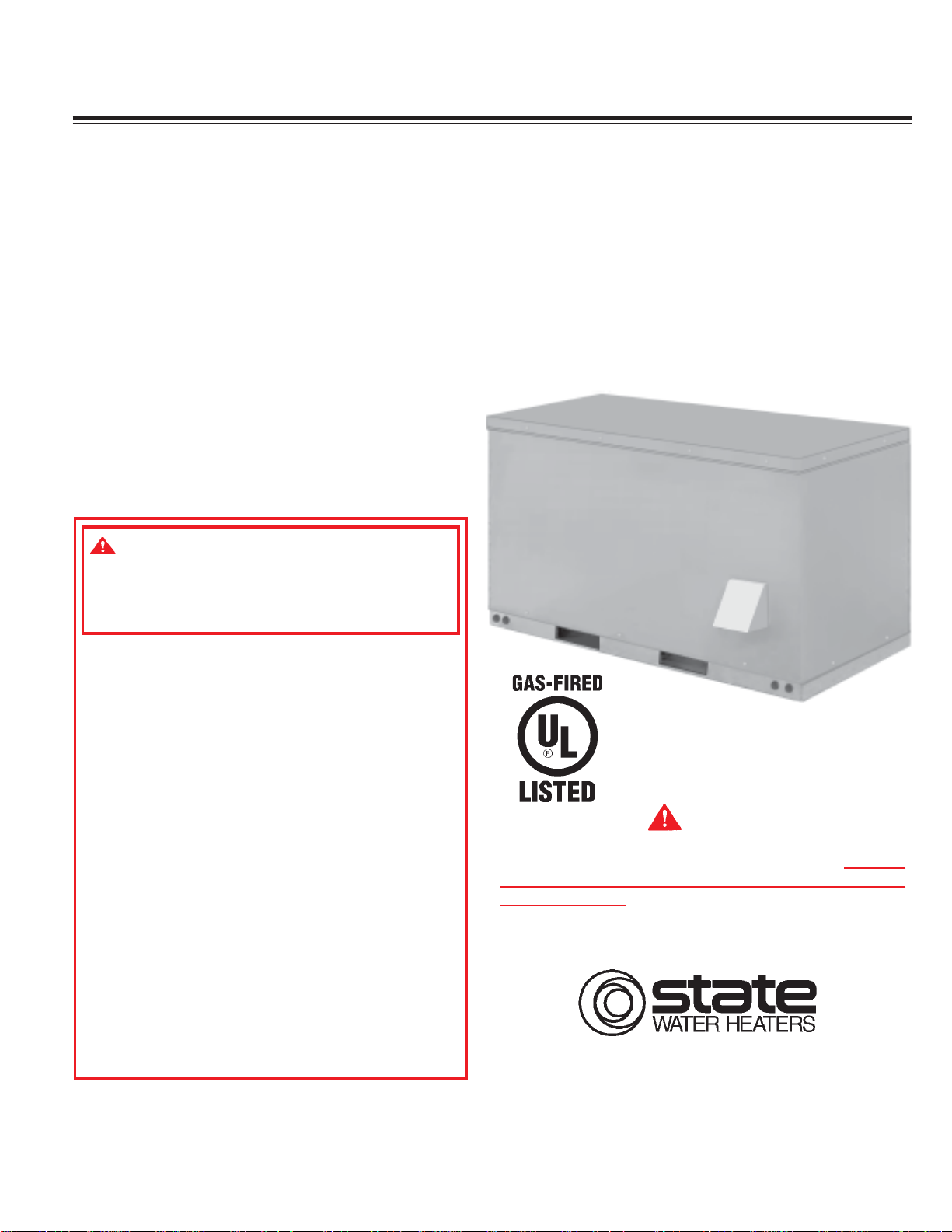
Rooftop Water Heater Model SRT80 1 20NE
COMMERCIAL GAS W A TER HEA TER
GAS-FIRED POWER BURNER
FOR DOMESTIC HOT W A TER
• INST ALLA TION • OPERA TION • SERVICE • MAINTENANCE • LIMITED W ARRANTY
Thank you for buying this energy efficient water heater from
State Industries. We appreciate your confidence in our
products.
W ARNING: If the information in these
instructions is not followed exactly , a fire
or explosion may result causing property
damage, personal injury or death.
– Do not store or use gasoline or other
flammable vapors and liquids in the
vicinity of this or any other appliance.
– WHAT TO DO IF YOU SMELL GAS:
• Do not try to light any appliance.
• Do not touch any electrical switch;
do not use any phone in your
building.
• Immediately call your gas supplier
from a neighbor's phone. Follow the
gas supplier's instructions.
• If you cannot reach your gas supplier,
call the fire department.
CAUTION
TEXT PRINTED OR OUTLINED IN RED CONTAINS
INFORMATION RELATIVE TO YOUR SAFETY. PLEASE
READ THOROUGHL Y BEFORE INST ALLING AND USING
THIS APPLIANCE.
– Installation and service must be
performed by a qualified installer,
service agency or the gas supplier .
PLACE THESE INSTRUCTIONS ADJACENT TO HEA TER AND
NOTIFY OWNER TO KEEP FOR FUTURE REFERENCE.
PRINTED IN U.S.A. 1005 PART NO. 1 97242-000
1
500 Tennessee Waltz Parkway
Ashland City, TN 37015
www.statewaterheaters.com
SUPERSEDES PART NO. 196758-000
Page 2
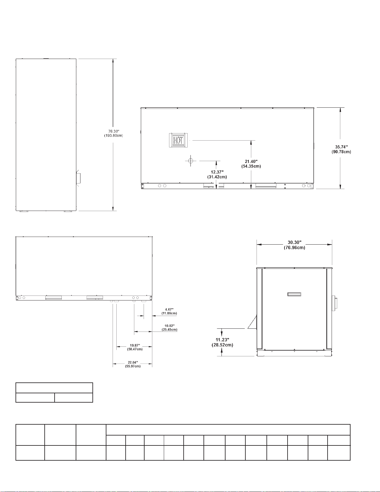
TOP VIEW
ROOFTOP SRT80-120NE
ROUGH-IN-DIMENSIONS
RIGHT SIDE VIEW
LEFT SIDE VIEW
GAS VAL VE PIPING
SRT80-120 1/2" NPT
FRONT VIEW
T able 1. RECOVERY CAP ACITIES - NA TURAL GAS / L.P.
BTU Gallon
Model Input Capacity 30 40 50 60 70 80 90 100 110 120 130 140
SRT80-120
Recovery capacities are based on heater performance at 80% thermal efficiency .
120,000 80 388 291 233 194 166 145 129 116 106 97 90 83
35.17 kwh 303L (1469) (1102) (882) (734) (628) (549) (488) (439) (401) (367) (341) (314)
Approx.
TEMPERATURE RISE - DEGREES °F - GALLONS PER HOUR (LPH)
2
Page 3
INST ALLA TION INFORMA TION
OUTBACK
Installation Information
Model: SRT 80-1 20NE series Input: 120,000 btuh
Electrical: 120/24V AC/60 Hz/5 A Side Clearances: 0"
Maximum Inlet Pressure: 14"WC T op Clearances: 1.50"
Manifold Pressure: 4.50"WC Unit is Polarity Sensitive
Minimum Inlet Pressure: 6.2"WC No external venting required
Warnings
Dummy hot return required if hot return from appliance is not used*
Avoid flex gas line usage
Avoid use of forklift truck to mount unit on outdoor stand
Provide enough clearance to service unit
Available Kits
Anti-freeze kit
Remote Interface kit
3
Page 4

FOREWORD
This design complies with the current edition of ANSI Z21.10.3 as
an automatic circulating tank type water heater and automatic
storage water heater.
Detailed installation diagrams are found in this manual. These
diagrams will serve to provide the installer with a reference for the
materials and methods of piping necessary. It is highly essential
that all water, gas piping and wiring be installed as shown on the
diagrams.
Particular attention should be given to the installation of
thermometers at the locations indicated on the diagrams as these
are necessary for checking the proper functioning of the heater.
TABLE OF CONTENTS
PAGE PAGE
ROUGH-IN DIMENSIONS .................................................................... 2
INST ALLATION INFORMA TION........................................................... 3
FOREWORD ....................................................................................... 4
FEATURES ......................................................................................... 5
Water Temperature Control........................................................... 5
High Limit Switch (E.C.O.) ............................................................. 6
Dishwashing Machine Requirement ............................................. 5
Circulating Pump............................................................................ 6
PLUMBING MANIFOLD ASSEMBL Y ................................................... 6
Flow Diagram ................................................................................ 5
Automatic Air Bleed Valve ............................................................ 5
Hot Return Recirculation Pump ..................................................... 7
Drain Valve.................................................................................... 7
AIR SYSTEM ASSEMBL Y .................................................................. 7
Blower Assembly.......................................................................... 7
Blower Plenum .............................................................................. 7
Air Hose ........................................................................................ 8
Flue Adapter.................................................................................. 8
Exhaust Vent ................................................................................. 8
CONTROL SYSTEM ........................................................................... 8
Blocked Outlet Switch .................................................................. 8
Blocked Inlet/Prover Switch .......................................................... 8
Low Gas Pressure Switch ........................................................... 9
On/Off Switch ............................................................................... 9
Hot Surface Igniter ........................................................................ 9
OIM - Outdoor Interface Module ................................................... 9
WR Ignition Control Board ............................................................. 9
Low Water Cutoff Board and Probe ............................................ 10
Thermostat/E.C.O. Probes ............................................................ 10
Transformer .................................................................................. 10
Junction Box ................................................................................. 10
TANK ASSEMBLY SYSTEM .............................................................. 10
T ank Insulation............................................................................... 10
CABINET ASSEMBLY......................................................................... 11
Cabinet Panels .............................................................................. 11
ADDITIONAL CONTROLS .................................................................. 11
Gas Valve ...................................................................................... 11
Flame Sensor ................................................................................ 11
INSTALLA TION INSTRUCTIONS ......................................................... 11
Required Ability ............................................................................. 11
Insulation Blankets ........................................................................ 11
Locating The Heater...................................................................... 11-12
Provide Unit Support ..................................................................... 12
Roof Curb ...................................................................................... 12-13
Rig and Place Unit ......................................................................... 13
Outdoor Stand ............................................................................... 14
Clearances .................................................................................... 14
Hard Water .................................................................................... 14
Air Requirements .......................................................................... 14
In addition to these instructions, the equipment shall be
installed in accordance with all local codes. The authority
having jurisdiction should be consulted before installing.
In the absence of local codes, the installation must comply
with the current editions of the National Fuel Gas Code,
ANSI Z223.1/NFPA 54 and the National Electric Code, NFPA 70.
The former is available from the Canadian Standards
Association, 8501 East Pleasant Valley Road, Cleveland, OH
44131, and both documents are available from the National
Fire Protection Association, 1 Batterymarch Park, Quincy, MA
02269.
Chemical Vapor Corrosion ............................................................ 14
VENTING ............................................................................................ 15
Vent Terminals ............................................................................... 15
Pressure Switches ....................................................................... 15
Gas Piping ..................................................................................... 15-16
Connection of Gas Pipe ................................................................ 16
Purging .......................................................................................... 16
Gas Meter Size - City Gases Only ............................................... 16
Gas Pressure Regulation.............................................................. 16
Gas Valves .................................................................................... 17
SYSTEM CONNECTIONS ................................................................... 17
Thermometers ............................................................................... 17
Relief Valve ................................................................................... 17
Water Line Connections ............................................................... 17
Closed System .............................................................................. 17
Water (Potable) Heating and Space Heating ................................ 17
Water Heater Wiring...................................................................... 17-18
OPERATION........................................................................................ 19-20
Sequence of Operation ................................................................ 21
Error Codes ................................................................................... 21
Fault Conditions............................................................................. 21-22
PRIOR TO ST ART-UP ......................................................................... 22
Required Ability ............................................................................. 22
OPERATING INSTRUCTIONS.............................................................. 23
Adjustment Procedure (Initial Start-Up) ........................................ 23-24
Cathodic Protection....................................................................... 24
Precautions ................................................................................... 24
Lighting & Operating Label............................................................ 25
GENERAL INFORMA TION .................................................................. 26
Power Burner ............................................................................... 26
High Limit ....................................................................................... 26
High Altitude Installations .............................................................. 26
MAINTENANCE .................................................................................. 26
General.......................................................................................... 26
Maintenance Schedule ................................................................. 26
Flushing ......................................................................................... 26
Draining ......................................................................................... 26
Sediment Removal......................................................................... 26
Lime Scale Removal ...................................................................... 26-27
Anode Inspection and Replacement............................................. 27
Drain Valve and Access Panels ................................................... 27
Relief Valve ................................................................................... 27
Circulating Pump............................................................................ 27
Vent System .................................................................................. 27
INSTALLA TION DIAGRAMS ............................................................... 28-32
CHECKLIST AND SERVICE INFORMATION ........................................ 33
TROUBLE-SHOOTING........................................................................ 33-34
REPLACEMENT PARTS ...................................................................... 34
LIMITED WARRANTY......................................................................... 35
4
Page 5
FEATURES
IMPORT ANT
IT IS REQUIRED THAT A QUALIFIED SERVICE TECHNICIAN
PERFORM THE INITIAL FIRING OF THE HEATER.
A CHECKLIST AND SER VICE INFORMATION section are included
at the rear of this manual. By using this checklist the user may be
able to make minor operational adjustments and save himself
unnecessary service calls. However, the user should not attempt
repairs which are not listed in this section.
WA TER TEMPERA TURE CONTROL
DANGER
THIS WATER HEATER IS EQUIPPED WITH AN ADJUSTABLE
THERMOSTAT TO CONTROL WATER TEMPERATURE. HOT
WATER TEMPERATURES REQUIRED FOR AUTOMATIC
DISHWASHER AND LAUNDRY USE CAN CAUSE SCALD BURNS
RESULTING IN SERIOUS PERSONAL INJURY AND/OR DEATH.
THE TEMPERATURE A T WHICH INJURY OCCURS V ARIES WITH
THE PERSON’S AGE AND TIME OF EXPOSURE. THE SLOWER
RESPONSE TIME OF CHILDREN, THE ELDERLY OR DISABLED
PERSONS INCREASES THE HAZARDS TO THEM. NEVER ALLOW
SMALL CHILDREN TO USE A HOT WATER TAP, OR TO DRAW
THEIR OWN BATH W A TER. NEVER LEAV E A CHILD OR DISABLED
PERSON UNATTENDED IN A BA THTUB OR SHOWER.
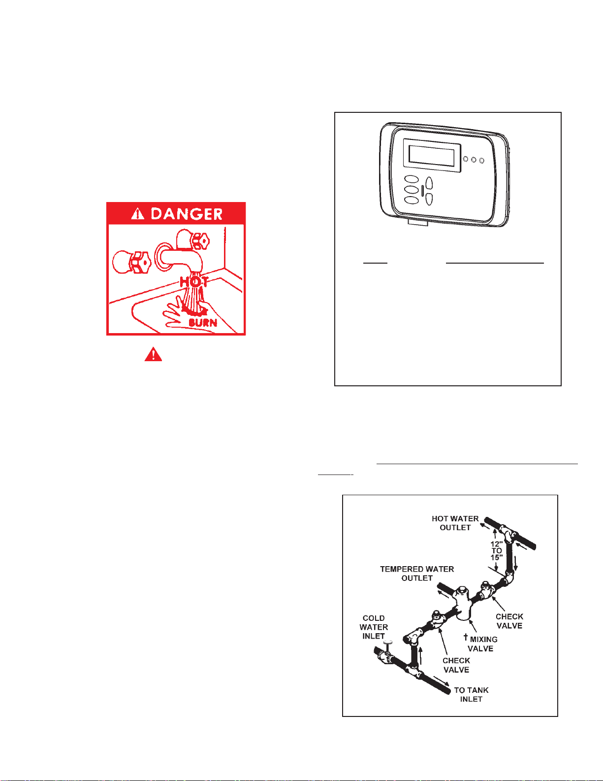
Figure 1 shows the approximate time-to-burn relationship for
normal adult skin. Short repeated heating cycles caused by small
hot water uses can cause temperatures at the point of use to
exceed the thermostat setting by up to 20°F/-1 1°C. If you experience
this type of use, you should consider using lower temperature
settings to reduce scald hazards.
Temperature Time to Produce 2nd & 3rd
Setting Degree Burns on Adult Skin
180°F / 82°C Nearly instantaneous
170°F / 77°C Nearly instantaneous
160°F / 71°C About 1/2 second
150°F / 66°C About 1-1/2 seconds
140°F / 60°C Less than 5 seconds
130°F / 54°C About 30 seconds
120°F / 49°C More than 5 minutes
FIGURE 1
Valves for reducing point-of-use temperature by mixing cold and
hot water are available (see Figure 2). Also available are
inexpensive devices that attach to faucets to limit hot water
temperatures. Contact a licensed plumber or the local plumbing
authority.
THE WA TER HEA TER SHOULD BE LOCA TED IN AN AREA WHERE
THE GENERAL PUBLIC DOES NOT HAVE ACCESS TO SET
TEMPERATURES.
The water temperature is controlled using the Touch Pad Buttons
on the Display at the front of the unit (See Figure 1). This control
utilizes two temperature probes to determine the tank temperature.
The upper temperature probe is located on top of the unit in the
back and the lower probe is located on the front center axis of the
tank.
The temperature may be adjusted from 70°F/21°C to 180°F/82°C.
The thermostat was adjusted to 70°F/21°C before the heater was
shipped from the factory. It is recommended that lower water
temperatures be used to avoid the risk of scalding. It is further
recommended, in all cases, that the water temperature be set for
the lowest temperature which satisfies your hot water needs. This
will also provide the most energy efficient operation of the water
heater and minimize scale formation.
SETTING THE WATER HEATER TEMPERATURE AT 120°F/49°C
WILL REDUCE THE RISK OF SCALDS. Some states require
settings at specific lower temperatures.
FIGURE 2
5
Page 6
HIGH LIMIT SWITCH (E.C.O.)
The top immersion well of the upper probe also contains the high
limit (energy cutoff) sensor. The high limit switch interrupts the
main burner gas flow should the water temperature reach
approximately 199°F/93°C.
Should the high limit switch activate, it must be reset by cycling
power to the unit. The water temperature must drop below 180°F/
82°C before the controller can be reset.
Continued manual resetting of the high limit control, preceded
by higher than usual water temperature is evidence of high
limit switch operation. For example, a malfunction of the control
system allowing the gas valve to stay open could cause water
temperature to rise until the high limit switch opens. Contact
your dealer or servicer if continued high limit switch operation
occurs.
DISHWASHING MACHINE REQUIREMENT
All dishwashing machines meeting the National Sanitation
Foundation requirements are designed to operate with water
flow pressures between 15 and 25 pounds per square inch
(103 kPa and 173 kPa). Flow pressures above 25 pounds per
square inch (173 kPa), or below 15 pounds per square inch
(103 kPa), will result in improperly sanitized dishes. Where
pressures are high, a water pressure reducing or flow
regulating control valve should be used in the 180°F (82°C)
line to the dishwashing machine, and should be adjusted to
deliver water between these limits.
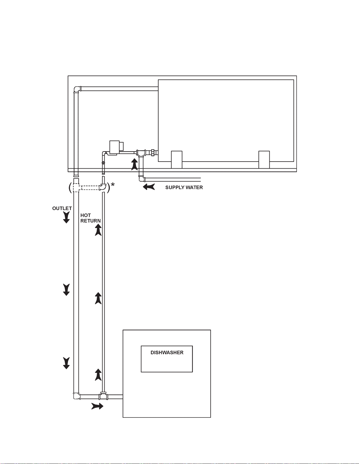
The National Sanitation Foundation also recommends circulation
of 180°F (82°C) water. Where this is done, the circulation should
be very gentle so that it does not cause any unnecessary
turbulence inside the water heater. The circulation should be
just enough to provide 180°F (82°C) water at the point of takeoff to the dishwashing machine. Adjust flow by means of the
plug cock in the circulating line. (See INSTALLATION DIAGRAMS
section.)
CIRCULATING PUMP
A circulating pump is used when a system requires a circulating
loop or there is a storage tank used in conjunction with the heater.
Refer to the piping diagrams at rear of manual for electrical hookup
information and install in accordance with the current version of
the National Electric Code NFPA No. 70.
All bronze circulators are recommended for use with commercial
water heaters.
Although circulators are oiled and operated by the manufacturer
some circulators must be oiled again before being operated.
Please refer to manufacturer's instructions.
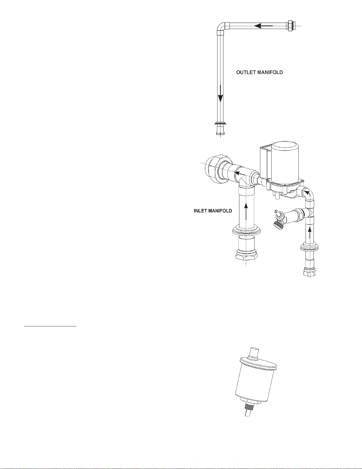
PLUMBING MANIFOLD ASSEMBLY
FLOW DIAGRAM
FIGURE 3
AUTOMA TIC AIR BLEED V AL VE
The tank assembly utilizes an automatic air bleed valve. The
purpose for this automatic air bleed valve is to allow air to escape
the tank when the unit is filled with water. When the unit is drained,
the opposite occurs with the valve allowing air to replace the drained
water. It removes the pressure vacuum that occurs in the system
causing incomplete drainage. This valve is automatic which allows
it to sense when the tank assembly is filled with water, see
Figure 4.
The plumbing manifold assembly is composed of several
components with each having a unique function. Please see
Figures 3, 5, and 6 to observe the water flow to the plumbing
manifold assembly and the components that make it up.
FIGURE 4
6
Page 7
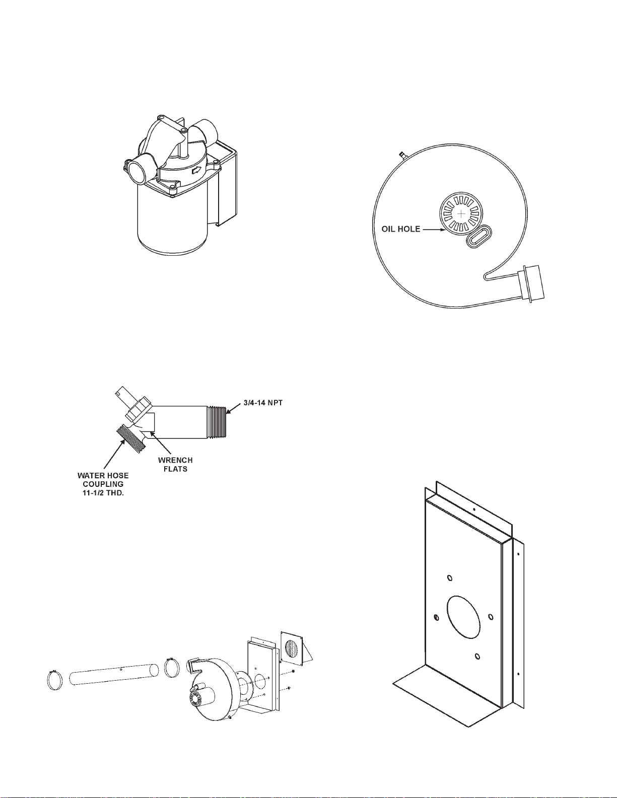
HOT RETURN RECIRCULA TION PUMP
BLOWER ASSEMBLY
The hot return recirculation pump circulates the hot water through
the hot water line to eliminate delays at plumbing fixtures, see
Figure 5.
FIGURE 5
DRAIN V ALVE
The drain valve is used to drain the water from the tank assembly
and plumbing manifold assembly, see Figure 6.
The blower assembly functions by pulling in air from outside the
unit to supply to the burner assembly for proper combustion. The
blower pushes the air through the burner assembly and heat
exchanger where the flue gases then exit the exhaust system
assembly, see Figure 8.
FIGURE 8
BLOWER PLENUM
FIGURE 6
AIR SYSTEM ASSEMBLY
The air system assembly is comprised of the blower assembly,
blower plenum, air hose, and inlet vent terminal. This is where
combustion air is acquired for combustion, see Figure 7.
The blower plenum is used to draw air into the blower inlet. The
inlet of the air system must maintain enough height from the ground
to take into account yearly snow levels to prevent possible inlet
vent blockage. The air plenum allows the blower to pull air into the
unit from a higher inlet location to provide protection required, see
Figure 9.
FIGURE 7
FIGURE 9
7
Page 8
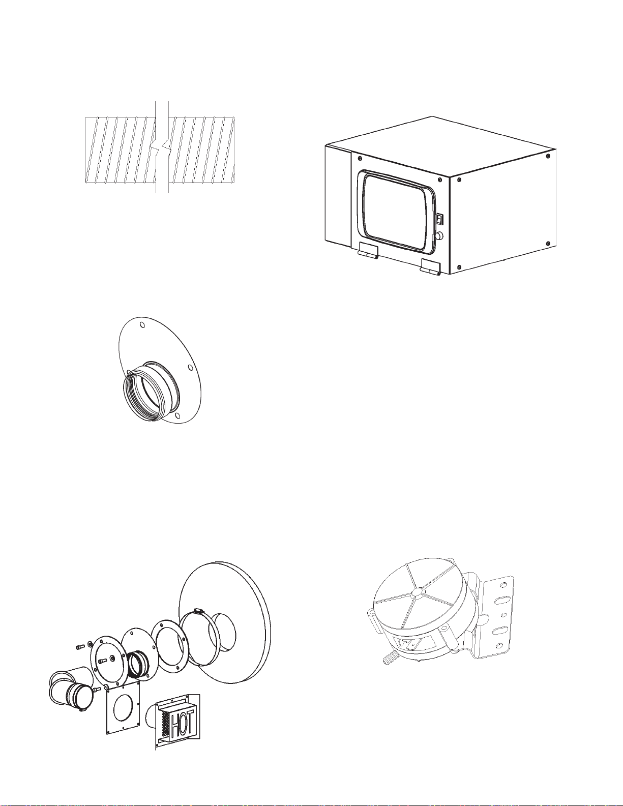
AIR HOSE
CONTROL SYSTEM
The air hose is used to provide a flexible air path from the blower
to the burner assembly. It is held in place with two standard hose
clamps, see Figure 10.
FIGURE 10
FLUE ADAPTER
The flue adapter is made of a flat metal plate with an exhaust
adapter to mate with the exhaust elbow. This is where the flue
gases exit the heat exchanger. This is a very hot region and is
covered with a layer of high temperature fiberglass insulation, see
Figure 11.
The control system is comprised of an Outdoor Interface Module
that monitors the functions of the WR ignition system, pressure
switches, low water cutoff and temperatures in the tank.
FIGURE 13
BLOCKED OUTLET SWITCH
The Blocked Outlet Switch is set up to shut the unit off when a
pressure buildup in the exhaust vent pipe occurs. This switch is a
positive pressure switch that requires an increase in pressure to
change the electrical contacts from normally closed to open. When
this switch prevents the unit from igniting, most likely the exhaust
is blocked. Check for obstructions in the exhaust venting and
exhaust vent terminal, see Figure 14.
FIGURE 11
EXHAUST VENT
The exhaust vent elbow mates with the flue adapter. The elbow
mates with the exhaust terminal to dispose the flue gases to the
outdoors. This venting section is covered with a fiberglass
insulated wrap to protect from heat and condensation. These
pipes are sealed with a high temperature gasket integral to the
vent pipe fittings, see Figure 12.
FIGURE 12
BLOCKED INLET/PROVER SWITCH
The Blocked Inlet/Prover Switch is set up to shut the unit off when
a reduction in pressure in the intake vent occurs. This switch is a
negative pressure switch that requires an increase in negative
pressure to change the electrical contacts from normally open to
closed. The switch is connected to the pressure tap connected to
the housing of the blower. When this switch prevents the unit from
ignition, most likely the intake is blocked. Check for obstructions in
the inlet vent terminal, see Figure 14.
FIGURE 14
The blocked Inlet/Prover Switch has a second function. It is provided
on the heater to verify that the fan is operating. When the fan
increases in negative pressure, the electrical contacts close
signaling that the blower is operational and is at peak performance.
The controller requires that the electrical contacts on the switch
close before it will allow the blower to come on.
8
Page 9
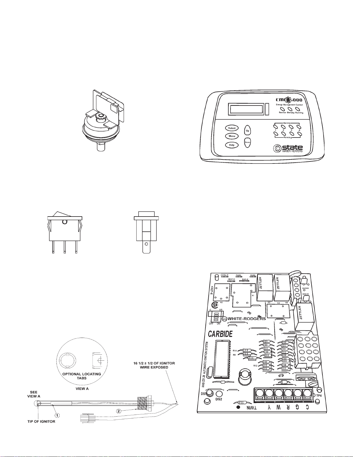
LOW GAS PRESSURE SWITCH
OIM - OUTDOOR INTERFACE MODULE
The Low Gas Pressure Switch is a single pole, normally open
pressure switch that will close its contacts when a rising pressure
of 6.2 inches (1.53 kPa) w.c. is encountered. The contacts will
open when the pressure falls below the fixed set point of 6.2 inches
of w.c. The Low Gas Pressure Switch monitors the gas supply
pressure to the heater. If the gas supply falls below the 6.2 inches
of w.c., the main burner is extinguished (if heater is running) or the
heater will not start up, see Figure 15.
FIGURE 15
ON/OFF SWITCH
The ON/OFF Switch is a single pole, single throw rocker switch.
This switch provides 120V from the electrical source to the heater,
see Figure 16.
The OIM is a device that monitors the control system. It monitors
the ignition control assembly, the tank and outlet temperatures,
the low water cutoff device, and the pressure switches. The display
board provides operating information. It records and logs error
messages for diagnostics. The module is equipped with a touch
pad for easy access to observe menus and current status of
control, see Figure 18.
FIGURE 18
WR IGNITION CONTROL BOARD
The WR Ignition Control Board performs the ignition sequence for
the water heater. It controls the diagnostics of the system and
monitors all the pressure switches, the flame sensing device, the
thermostats, the E.C.O., and components that make up the control
system. The difference between the WR Ignition Control Board is
that the OIM board monitors all the controls and provides that
information through the LCD display where the WR Ignition Control
Board provides the means to control the complete sequence of
operation and switches, see Figure 19.
FIGURE 16
HOT SURFACE IGNITER
The Hot Surface Igniter is a device that ignites the main burner by
high temperature (1800°F). When the 120 VAC is applied to the
igniter, sufficient heat is generated to ignite the main burner.
Although improvements have been made to strengthen the igniter,
it is still fragile and care must be taken when handling the igniter to
prevent breakage, see Figure 17.
FIGURE 17
FIGURE 19
9
Page 10
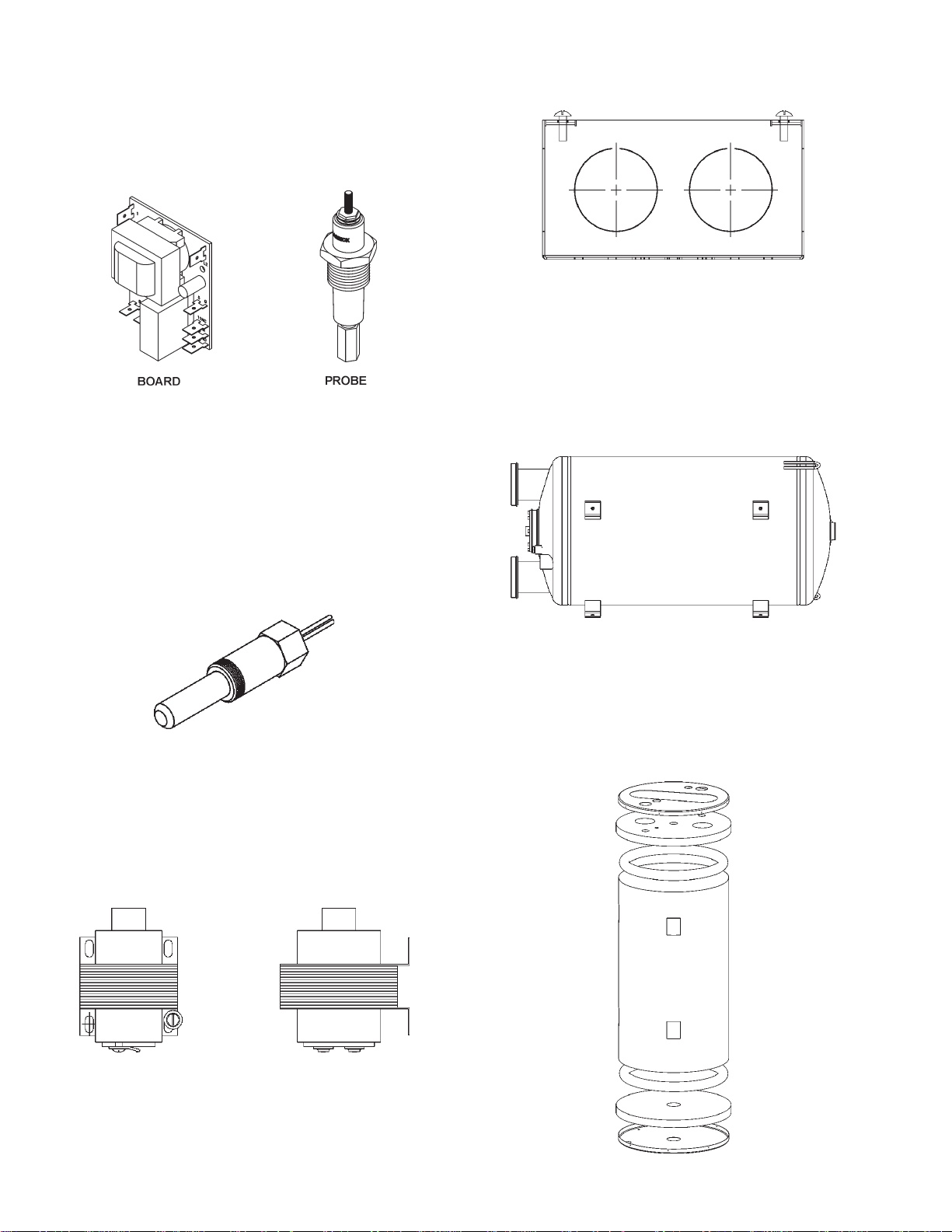
LOW WA TER CUT OFF BOARD AND PROBE
The Low Water Cutoff Board and Probe monitors the water level to
confirm the tank is completely full. This function is very important
when the unit is first filled with water and when complete loss of
power is encountered during freezing temperatures (in case the
unit drains while using the anti-freeze kit), see Figure 20.
FIGURE 20
THERMOST A T/E.C.O. PROBES
The Outback utilizes a two probe system. The upper probe located
on top of the unit toward the back of the cabinet consists of a
thermostat and E.C.O. The thermostat monitors the top temperature
in the tank. The E.C.O. high limit switch interrupts the main burner
gas flow should the water temperature reach approximately 205°F.
The lower probe measures the water temperature in the lower half
of the tank assembly.
grounding screw to tie into the metal panel to assure the unit is
grounded, see Figure 23.
FIGURE 23
TANK ASSEMBLY SYSTEM
The Tank Assembly is an 80 gallon unit with a U-shaped heat
exchanger. It incorporates two inlet tubes to control flow inside the
tank. The heat exchanger is equipped with a stainless steel baffle
which is non-removable. The working pressure is 150 psi, see
Figure 24.
FIGURE 21
TRANSFORMER
The control system utilizes a 120/24 VAC step down transformer.
Most of the control system utilizes 24 VAC for operation. See wiring
diagram for those components utilizing 24 VAC and 120 VAC, see
Figure 22.
FIGURE 22
FIGURE 24
TANK INSULA TION
The tank assembly is wrapped in foam insulation sealed inside a
round jacket. The ends of the tank consist of high temperature
fiberglass insulation and foam dams to prevent foam leakage,
see Figure 25.
JUNCTION BOX
The junction box is where the 120 VAC is supplied to the unit and
tied into the rest of the controls. The junction box provides a
FIGURE 25
10
Page 11
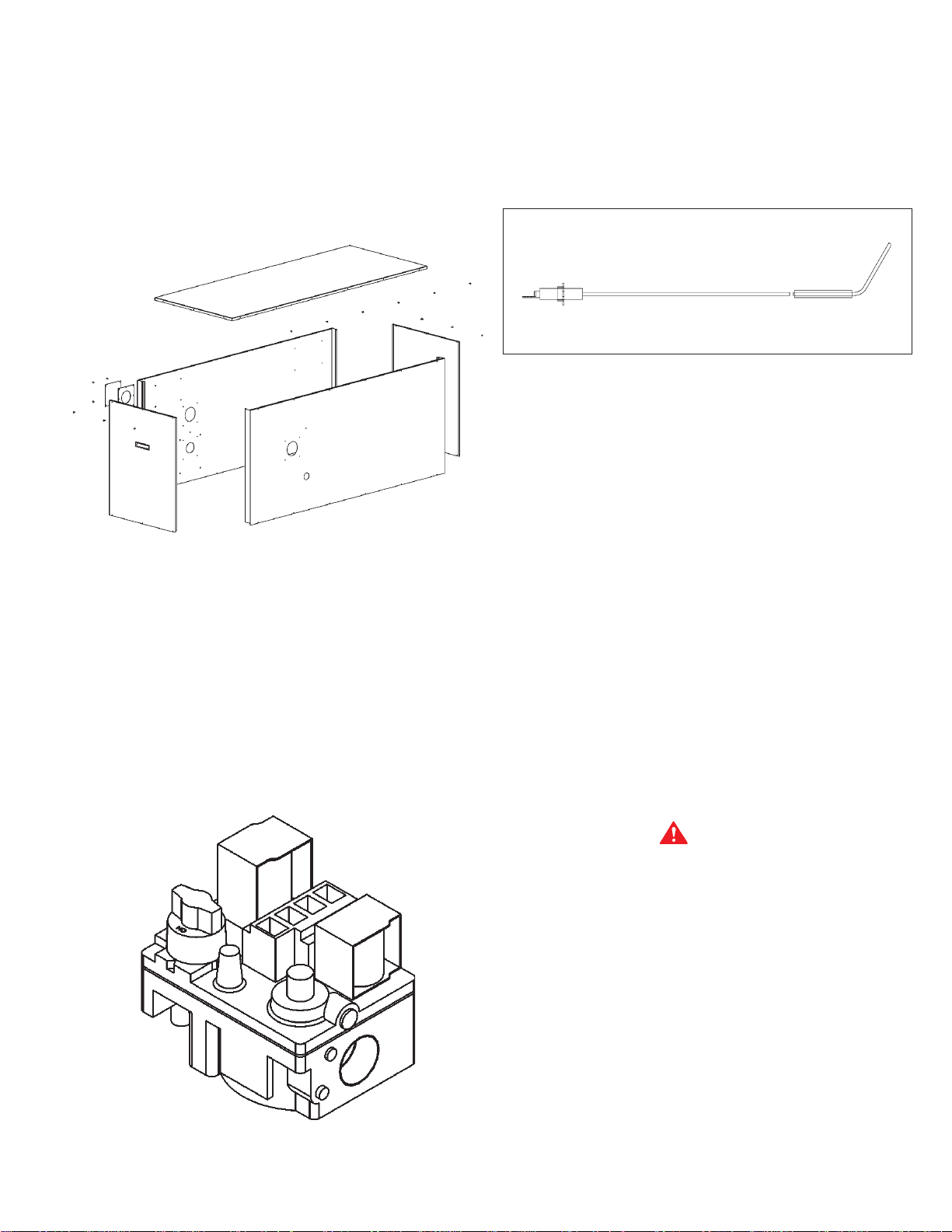
CABINET ASSEMBLY
FLAME SENSOR
CABINET P ANELS
There are five panels that comprise the cabinet assembly. The
ends of the cabinet allow access to all controls and plumbing.
Please confirm all joints are attached correctly and sealed to
prevent water leakage inside the cabinet, see Figure 26.
FIGURE 26
The flame sensor is used to sense the burner flame. When there
is sufficient flame, and the burner is properly grounded, the flame
sensor signals back to the ignition board that the burner is operating
properly and to maintain the operation of the gas valve until the
thermostat is satisfied.
FIGURE 28
INSTALLATION INSTRUCTIONS
REQUIRED ABILITY
INSTALLA TION OR SERVICE OF THIS WA TER HEATER REQUIRES
ABILITY EQUIV ALENT TO THAT OF A LICENSED TRADESMAN IN
THE FIELD INVOL VED. PLUMBING , AIR SUPPL Y , VENTING, GAS
SUPPL Y AND ELECTRICAL WORK ARE REQUIRED.
INSULA TION BLANKETS
ADDITIONAL CONTROLS
GAS V AL VE
The gas valve is used to supply the gas to the unit during heat up
periods. The ignition control board monitors the thermostat's call
for heat and sends a signal to the gas valve when to open to allow
gas flow, see Figure 27.
Insulation blankets available to the general public for external use
on gas water heaters are not approved for use on your State
water heater. The purpose of an insulation blanket is to reduce the
standby heat loss encountered with storage tank water heaters.
Yo ur State water heater meets or exceeds the ASHRAE/IES 90.1 b
1999 standards with respect to insulation and standby loss
requirements, making an insulation blanket unnecessary.
LOCA TING THE HEATER
WARNING
THERE IS A RISK IN USING FUEL BURNING APPLIANCES SUCH
AS GAS WATER HEATERS IN ROOMS, GARAGES OR OTHER
AREAS WHERE GASOLINE, OTHER FLAMMABLE LIQUIDS OR
ENGINE DRIVEN EQUIPMENT OR VEHICLES ARE STORED,
OPERATED OR REP AIRED. FLAMMABLE V APORS ARE HEA VY AND
TRAVEL ALONG THE FLOOR AND MAY BE IGNITED BY THE
HEA TER’S IGNITER OR MAIN BURNER FLAMES CAUSING FIRE
OR EXPLOSION. SOME LOCAL CODES PERMIT OPERA TION OF
GAS APPLIANCES IF INSTALLED 18 INCHES (46 cm) OR MORE
ABOVE THE FLOOR. THIS MAY REDUCE THE RISK IF LOCATION
IN SUCH AN AREA CANNOT BE AVOIDED.
THE HEATER SHALL BE LOCATED OR PROTECTED SO IT IS
NOT SUBJECT TO PHYSICAL DAMAGE BY A MOVING VEHICLE.
FIGURE 27
DO NOT LOCATE THE HEATER WHERE NOISE FROM THE
EXHAUST OR INTAKE WILL BE OBJECTIONABLE. THIS
INCLUDES LOCATIONS CLOSE T O OR ACROSS FROM WINDOWS
AND DOORS.
11
Page 12

FIGURE 29
WARNING
FLAMMABLE ITEMS, PRESSURIZED CONTAINERS OR ANY
OTHER POTENTIAL FIRE HAZARDOUS ARTICLES MUST NEVER
BE PLACED ON OR ADJACENT TO THE HEATER. OPEN
CONTAINERS OF FLAMMABLE MATERIAL SHOULD NOT BE
STORED OR USED IN THE SAME ROOM WITH THE HEA TER.
Water heater life depends upon water quality, water pressure and
the environment in which the water heater is installed. Water
heaters are sometimes installed in locations where leakage may
result in property damage, even with the use of a drain pan piped
to a drain. However, unanticipated damage can be reduced or
prevented by a leak detector or water shutoff device used in
conjunction with a piped drain pan. These devices are available
from some plumbing supply wholesalers and retailers, and detect
and react to leakage in various ways:
• Sensors mounted in the drain pan that trigger an alarm or turn
off the incoming water to the water heater when leakage is
detected.
• Sensors mounted in the drain pan that turn off the water supply
to the entire home when water is detected in the drain pan.
• Water supply shutoff devices that activate based on the water
pressure differential between the cold water and hot water
pipes connected to the water heater.
• Devices that will turn off the gas supply to a gas water heater
while at the same time shutting off its water supply.
PROVIDE UNIT SUPPORT
the unit full of water. (Full weight of approximately 1300 lbs. Add
extra load and safety factors.) This is very important and the user's
responsibility, see Figure 29. If you are uncertain as to the load
bearing capability of the roof, consult a licensed structural
engineering expert.
The unit should be placed on a solid level roof curb of adequate
strength. A properly designed roof curb is provided through
State Order Entry.
IMPORTANT: THE W ATER HEA TER SHOULD BE EMPTY OF WA TER
DURING LIFTING . MAKE SURE ALL F ASTENERS ON THE BASE OF
THE UNIT ARE IN PLACE DURING LIFTING .
The location of the unit on the roof should be such that exhaust
gas is not located near any air intakes or ventilation ducts.
Provide a minimum of 36" on each side of the unit for servicing.
Plumbing connections for water are made from inside the building.
Gas and electric connections are made from the rooftop. Remote
control wiring passes through the leak-tight fitting in the base of
the unit.
ROOF CURB
Assemble and install accessory roof curb in accordance with
instructions shipped with curb.
IMPORT ANT : THE GASKETING OF THE UNIT TO THE ROOF CURB
IS CRITICAL FOR A WATER TIGHT SEAL. INSTALL GASKET
SUPPLIED WITH THE ROOF CURB AS SHOWN IN FIGURE 30.
Before locating the unit on the roof, make sure the strength of the
roof and beams are adequate at that point to support the weight of
Curb should be level. Refer to Accessory Roof Curb Installation
Instructions for additional information as required.
12
Page 13

FIGURE 30
RIG AND PLACE UNIT
Inspect unit for transportation damage. File any claim with
transportation agency . Keep unit upright and do not drop. Spreader
bars are not required if top crating is left on unit. Rollers may be
used to move unit across the roof. Level the unit by using unit
frame.
Lifting holes are provided in base rails as shown in Figure 31. All
panels must be in place when rigging.
The unit cannot be placed on the curb with a fork lift or other lifting
device through the fork lift openings. Doing so would interfere with
placement on the roof curb.
Maintain clearance around and above the unit to provide minimum
distance from combustible materials, proper air flow, and service
access.
Do not install unit in an indoor location. Do not locate unit air inlets
near exhaust vents or other sources of contaminated air.
Be sure that unit is installed such that snow will not block the
combustion intake or flue outlet.
Unit may be installed directly on wood flooring or on Class A, B, or
C roof covering material when roof curb is used.
Although unit is weatherproof, guard against water from higher
level runoff and overhangs.
Exhaust vent terminal must have a minimum horizontal clearance
of 4 ft. from electric and gas meters, gas regulators, and gas relief
equipment. Minimum distance between unit and other electrically
live parts is 48 inches.
Flue gases can deteriorate building materials. Orient unit such
that flue gas will not affect building materials.
Adequate combustion and ventilation air space must be provided
for proper operation of this equipment.
After unit is in position, remove rigging skids and shipping
materials.
FIGURE 31
13
Page 14

OUTDOOR ST AND
This rooftop water heater is approved for an outdoor installation
with an optional stand. Contact State Order Entry to acquire
optional stand kit.
WARNING
DO NOT USE THIS APPLIANCE IF ANY P ART HAS BEEN UNDER
WA TER. IMMEDIA TEL Y CONT ACT A QUALIFIED INST ALLER OR
SERVICE AGENCY TO REPLACE A FL OODED WATER HEATER.
DO NOT A TTEMPT T O REPAIR THE UNIT! IT MUST BE REPLACED!
The rooftop stand is constructed of a tubular steel frame along
with tubular steel legs. See Figure 32. The legs are three feet in
length and slide into the corners of the tubular steel frame. The
legs may be cut to length to reduce the overall height of the stand
if necessary.
The rooftop unit is located on the stand the same way as located
on the roof curb. Please locate panels at one end of the stand.
This area is used to run the water lines into the rooftop unit. It
provides added protection to the water lines. For additional
information see Optional Stand Kit Instructions.
CLEARANCES
These heaters are approved for outdoor installations on
combustible flooring (roof) with the minimum clearances of 0" for
sides and 1.50" for top.
Always disconnect electrical power before servicing the unit.
HARD W A TER
Where hard water conditions exist, water softening or the
threshold type of water treatment is recommended. This will
protect the dishwashers, coffee urns, water heaters, water
piping and other equipment.
See MAINTENANCE section for details of tank cleanout procedure.
AIR REQUIREMENTS
KEEP APPLIANCE AREA CLEAR AND FREE OF COMBUSTIBLE
MATERIALS, GASOLINE AND OTHER FLAMMABLE V APORS AND
LIQUIDS.
DO NOT OBSTRUCT THE FLOW OF COMBUSTION AND
VENTILATING AIR.
FIGURE 32
When installing the heater, consideration must be given to proper
location. Location selected should be as close to the intake and
exhaust termination points as practicable, with adequate air supply
and as centralized with the piping system as possible.
LOCA TE IT NEAR A DRAIN. THE HEA TER SHOULD BE LOCA TED
IN AN AREA WHERE LEAKAGE FROM THE HEATER OR
CONNECTIONS WILL NOT RESULT IN DAMAGE TO THE
ADJACENT AREA OR TO LOWER FLOORS OF THE STRUCTURE.
When such locations cannot be avoided, it is recommended that a
suitable drain pan, adequately drained, be installed under the
appliance.
State Water Heater provides an after market anti-freeze kit for use
when there is a loss of power. This kit provides drainage to the
tank and plumbing manifold to prevent freeze-up. When power is
restored, the system is equipped with automatic air bleed and a
low-water cut-off device to prove the tank is full of water prior to
startup. See kit instructions for complete details.
WARNING
FOR SAFE OPERATION PROVIDE ADEQUATE AIR FOR
COMBUSTION AND VENTILATION. AN INSUFFICIENT SUPPLY OF
AIR WILL CAUSE RECIRCULATION OF COMBUSTION
PRODUCTS RESULTING IN CONTAMINATION THAT MAY BE
HAZARDOUS TO LIFE. SUCH A CONDITION OFTEN WILL RESUL T
IN A YELLOW, LUMINOUS BURNER FLAME, CAUSING
CARBONING OR SOOTING OF THE COMBUSTION CHAMBER,
BURNERS AND FLUE TUBES AND CREATES A RISK OF
ASPHYXIATION.
CHEMICAL V APOR CORROSION
WARNING
CORROSION OF THE FLUE WAYS AND VENT SYSTEM MAY
OCCUR IF AIR FOR COMBUSTION CONTAINS CERTAIN
CHEMICAL VAPORS. SUCH CORROSION MAY RESULT IN
FAILURE AND RISK OF ASPHYXIATION.
Spray can propellants, cleaning solvents, refrigerator and air
conditioning refrigerants, swimming pool chemicals, calcium and
sodium chloride, waxes, and process chemicals are typical
compounds which are potentially corrosive.
PRODUCTS OF THIS SORT SHOULD NOT BE STORED NEAR
THE HEATER. ALSO, AIR WHICH IS BROUGHT IN CONT ACT WITH
THE HEATER SHOULD NOT CONTAIN ANY OF THESE
CHEMICALS. IF NECESSARY , UNCONT AMINA TED AIR SHOULD
BE OBTAINED FROM REMOTE OR OUTSIDE SOURCES.
14
Page 15

VENTING
WARNING
THE INSTRUCTIONS IN THIS SECTION ON VENTING MUST
BE FOLLOWED TO AVOID CHOKED COMBUSTION OR
RECIRCULATION OF FLUE GASES. SUCH CONDITIONS CAUSE
SOOTING OR RISKS OF FIRE AND ASPHYXIATION.
WARNING
NEVER OPERATE THE HEATER UNLESS IT IS VENTED TO
THE OUTDOORS AND HAS ADEQUATE AIR SUPPLY TO AVOID
RISKS OF IMPROPER OPERATION, FIRE, EXPLOSION OR
ASPHYXIATION.
CAUTION
DO NOT TERMINA TE THE VENTING WHERE NOISE FROM THE
EXHAUST OR INTAKE WILL BE OBJECTIONABLE. THIS
INCLUDES LOCATIONS CLOSE T O OR ACROSS FROM WINDOWS
AND DOORS.
The vent shall terminate a minimum of 12" (30.5 cm) above expected
snowfall level to prevent blockage of vent termination.
WARNING
USE ONLY THE VENT TERMINALS SUPPLIED WITH THIS UNIT .
TERMINATION OF A VENT SYSTEM WITH A DEVICE OTHER
THAN THE SUPPLIED VENT TERMINATIONS WILL AFFECT
SYSTEM PERFORMANCE AND RESULT IN A SAFETY HAZARD.
PRESSURE SWITCHES
The SRT80-120NE is provided with three pressure switches.
These switches are essential to the safe and proper operation of
the unit. All switches are wired in series. The controller is set up to
shut the unit down whenever there is a failure of any of the switches.
CAUTION
THE WATER HEATER IS POLARITY SENSITIVE. BEFORE
APPLYING ELECTRICITY TO THIS HEATER BE CERTAIN THAT
SUPPLY NEUTRAL WIRE TO GROUND CHECK INDICA TES ZERO
VOLTAGE.
GAS PIPING
Contact your local gas service company to ensure that adequate
gas service is available and to review applicable installation codes
for your area.
FIGURE 33
VENT TERMINALS
The vent system must terminate so that proper clearances are
maintained as cited in local codes or the current edition of the
National Fuel Gas Code, ANSI Z223.1/NFPA 54.
The SRT80-120NE series is designed with an internal vent
construction. The exhaust vent terminal and the inlet air terminal
are located on the sides of the appliance. Do not add vent pipe to
the appliance, see Figure 33.
Assure the exhaust vent terminal is not in a public area where the
hoods are exposed. The exhaust vent terminal gets very HOT
during operation and can cause burns. Please use caution when
working around the exhaust vent terminal.
It is imperative that the area around the vent terminal hoods are
kept clear from obstructions so plenty of fresh air is available for
combustion.
MAXIMUM CAP ACITY OF PIPE IN CUBIC FEET OF GAS PER HOUR
(Based upon a Pressure Drop of 0.5 inch Water Column
LENGTH NORMAL IRON PIPE SIZES (INCHES)
IN INPUT IN THOUSANDS BTU/HR
FEET 1/2" 3/4" 1" 1 1/4" 1 1/2" 2" 2 1/2" 3" 4"
10 175 360 680 1400 2100 3960 6300 11000 23000
20 120 250 485 950 1460 2750 4360 7700 15800
30 — 200 375 770 1180 2200 3520 6250 12800
40 — 170 320 660 990 1900 3000 5300 10900
50 — 151 285 580 900 1680 2650 4750 9700
60 — 138 260 530 810 1520 2400 4300 8800
70 — 125 240 490 750 1400 2250 3900 8100
80 — — 220 460 690 1300 2050 3700 7500
90 — — 205 430 650 1220 1950 3450 7200
100 — — 195 400 620 1150 1850 3250 6700
125 — — 175 360 550 1020 1650 2950 6000
150 — — 160 325 500 950 1500 2650 5500
175 — — 145 300 460 850 1370 2450 5000
200 — — 135 280 430 800 1280 2280 4600
LENGTH NORMAL IRON PIPE SIZES (INCHES)
IN INPUT IN KW
METERS 1/2" 3/4" 1" 1 1/4" 1 1/2" 2" 2 1/2" 3" 4"
3.0 51 105 199 410 615 1160 1845 3221 6735
6.1 35 73 142 278 428 805 1277 2255 4626
9.1 — 59 11 0 225 346 644 1031 1830 3748
12.2 — 50 94 193 290 556 878 1552 3192
15.2 — 44 83 170 264 492 776 1391 2840
18.3 — 40 76 155 237 445 703 1259 2577
21.3 — 37 70 143 220 410 659 1142 2372
24.4 — — 64 135 202 381 600 1083 2196
27.4 — — 60 126 190 357 571 1010 2108
30.5 — — 57 1 1 7 182 337 542 952 1962
38.1 — — 51 105 161 299 483 864 1757
45.7 — — 47 95 146 278 439 776 1610
53.3 — — 42 88 135 249 401 717 1464
61.0 — — 40 82 126 234 375 688 1347
and 0.6 Specific Gravity Gas
TABLE 3
Size the main gas line in accordance with Table 3. The figures
shown are for straight lengths of pipe at 0.5 in. (125 kPa) W.C.
pressure drop, which is considered normal for low pressure
systems. Note that fittings such as elbows and tees will add to the
pipe pressure drop.
CAUTION
DO NOT USE FLEXIBLE GAS PIPING .
15
Page 16

WARNING
THE HEATER IS NOT INTENDED FOR OPERATION AT HIGHER
THAN 14.0" WATER COLUMN (1/2 POUND OR 3.45 kPa PER
SQUARE INCH) SUPPLY GAS PRESSURE. HIGHER GAS SUPPLY
PRESSURES REQUIRE SUPPLEMENTAL REDUCING SERVICE
REGULA TION. EXPOSURE TO HIGHER GAS SUPPL Y PRESSURE
MA Y CAUSE DAMAGE TO THE GAS CONTROLS WHICH COULD
RESULT IN FIRE OR EXPLOSION. IF OVERPRESSURE HAS
OCCURRED SUCH AS THROUGH IMPROPER TESTING OF GAS
LINES OR EMERGENCY MALFUNCTION OF THE SUPPL Y SYSTEM
THE GAS VALVE MUST BE CHECKED FOR SAFE OPERATION.
MAKE SURE THAT THE OUTSIDE VENTS ON THE SUPPLY
REGULATORS AND THE SAFETY VENT VALVES ARE PROTECTED
AGAINST BLOCKAGE. THESE ARE P ARTS OF THE GAS SUPPLY
SYSTEM, NOT THE HEATER. VENT BLOCKAGE MAY OCCUR
DURING ICE STORMS.
IT IS IMPORT ANT TO GUARD AGAINST GAS V ALVE FOULING FROM
CONT AMINANTS IN THE GAS WA YS. SUCH FOULING MA Y CAUSE
IMPROPER OPERATION, FIRE OR EXPLOSION.
IF COPPER SUPPLY LINES ARE USED THEY MUST BE
INTERNALL Y TINNED AND CERTIFIED FOR GAS SERVICE.
BEFORE AT TACHING THE GAS LINE BE SURE THAT ALL GAS
PIPE IS CLEAN ON THE INSIDE.
TO TRAP ANY DIRT OR FOREIGN MATERIAL IN THE GAS SUPPL Y
LINE, A DIR T LEG (SOMETIMES CALLED A SEDIMENT TRAP OR
DRIP LEG) MUST BE INCORPORA TED IN THE PIPING . THE DIRT
LEG MUST BE READILY ACCESSIBLE AND NOT SUBJECT TO
FREEZING CONDITIONS. INSTALL IN ACCORDANCE WITH
RECOMMENDATIONS OF SERVING GAS SUPPLIERS. REFER TO
NATIONAL FUEL GAS CODE.
THE
Apply joint compounds (pipe dope) sparingly and only to the male
threads of pipe joints. Do not apply compound to the first two
threads. Use compounds resistant to the action of liquefied
petroleum gases.
DISCONNECT THE APPLIANCE AND ITS MANUAL GAS SHUTOFF
VALVE FROM THE GAS SUPPLY PIPING SYSTEM DURING ANY
SUPPL Y PRESSURE TESTING EXCEEDING 1/2 PSIG (3.45 kPa).
GAS SUPPL Y LINE MUST BE CAPPED WHEN DISCONNECTED
FROM THE HEA TER. FOR TEST PRESSURES OF 1/2 PSIG (3.45
kPa). OR LESS, THE APPLIANCE NEED NOT BE DISCONNECTED,
BUT MUST BE ISOLA TED FROM THE SUPPL Y PRESSURE TEST
BY CLOSING THE MANUAL GAS SHUTOFF V AL VE.
BEFORE PLACING THE HEATER IN OPERATION, CHECK FOR
GAS LEAKAGE. USE SOAP AND W A TER SOLUTION OR OTHER
MATERIAL ACCEPT ABLE FOR THE PURPOSE OF LOCA TING GAS
LEAKS. DO NOT USE MA TCHES, CANDLES, FLAME OR OTHER
SOURCES OF IGNITION FOR THIS PURPOSE.
PURGING
Gas line purging is required with new piping or systems in
which air has entered.
CAUTION
PURGING SHOULD BE PERFORMED BY PERSONS
EXPERIENCED IN THIS TYPE OF GAS SERVICE. TO A VOID RISK
OF FIRE OR EXPLOSION, PURGE DISCHARGE MUST NOT ENTER
CONFINED AREAS OR SP ACES WHERE IGNITION CAN OCCUR.
THE AREA MUST BE WELL VENTILA TED AND ALL SOURCES OF
IGNITION MUST BE INACTIV ATED OR REMOVED.
GAS METER SIZE - CITY GASES ONL Y
FIGURE 34
CONNECTION OF GAS PIPE
W ARNING
PERFORM THE GAS LEAK TEST ANY TIME WORK IS DONE ON A
GAS SYSTEM TO AVOID THE POSSIBILITY OF FIRE OR
EXPLOSION WITH PROPERTY DAMAGE, PERSONAL INJURY OR
LOSS OF LIFE.
The gas leak test is performed as follows: Paint pipe connections
upstream of gas control with a rich soap and water solution to test
for leaks before operating main burner. Bubbles indicate gas leak.
To stop leak, tighten pipe connections. After piping connections
are checked, turn on main burner. With main burner in operation,
paint pipe joints (including flanges), pilot gas tubing connections
and control inlet and outlet with rich soap and water solution.
Bubbles indicate gas leak. To stop leak, tighten flange screws,
joints and pipe connections. Replace part if leak can’t be stopped.
To prevent damage, care must be taken not to apply too much
torque when attaching gas supply pipe to gas valve inlet.
Be sure that the gas meter has sufficient capacity to supply the full
rated gas input of the water heater as well as the requirements of
all other gas fired equipment supplied by the meter. If the gas
meter is too small, ask the gas company to install a larger meter
having adequate capacity.
GAS PRESSURE REGULA TION
Main line gas pressure to the water heater should be between a
maximum 14.0" (3.45 kPa). W.C. and a minimum of 6.2 W.C. (1.53
kPa).
The inlet gas pressure must not exceed the maximum value. A
service regulator must be installed within 10' (305 cm) of unit.
GAS VAL VES
WARNING
SHOULD OVERHEATING OCCUR OR THE GAS SUPPL Y F AIL T O
SHUT OFF , TURN OFF THE MANUAL GAS CONTROL VAL VE TO
THE APPLIANCE.
SYSTEM CONNECTIONS
The system installation must conform to these instructions and to
the local code authority having jurisdiction. Good practice requires
that all heavy piping be supported.
THERMOMETERS (Not Supplied)
Thermometers should be obtained and field installed as shown
in the installation diagrams.
16
Page 17

Thermometers are installed in the system as a means of detecting
the temperature of the outlet water supply.
bypass) is installed in the cold water line between the water heater
and street main (or well).
RELIEF VAL VE
This heater is equipped with an approved temperature and
pressure relief valve. ASME ratings cover pressure relief. CSA
ratings cover release rate with temperature actuation.
FOR SAFE OPERATION OF THE WATER HEATER, THE RELIEF
VAL VE(S) MUST NOT BE REMOVED OR PLUGGED.
In addition to the appliance relief valve, each remote storage tank
which may be used in conjunction with this appliance shall also
be installed with a properly sized, rated and approved temperature
(ANSI) and pressure (ASME) relief valve(s). This relief valve shall
comply with the standard for relief valves and automatic gas shutoff
devices for hot water supply systems, ANSI Z21.22.
Your local code authority may have other specific relief valve
requirements.
WARNING
THE PURPOSE OF A RELIEF VALVE IS TO AVOID EXCESSIVE
PRESSURE OR TEMPERATURE INTO THE STEAM RANGE,
WHICH MA Y CAUSE SCALDING A T FIXTURES, TANK EXPLOSION,
SYSTEM OR HEATER DAMAGE. NO VALVE IS TO BE PLACED
BETWEEN THE RELIEF VALVE AND THE T ANK.
A DRAIN LINE MUST BE CONNECTED TO THE RELIEF V AL VE TO
DIRECT DISCHARGE TO A SAFE LOCA TION TO A VOID SCALDING
OR WA TER DAMAGE. THIS LINE MUST NOT BE REDUCED FROM
THE SIZE OF THE VALVE OUTLET AND MUST NOT CONTAIN
V ALVES OR RESTRICTIONS, NOR SHOULD IT BE LOCATED IN
FREEZING AREAS. DO NOT THREAD OR CAP THE END OF THIS
LINE. RESTRICTED OR BLOCKED DISCHARGE WILL DEFEAT
THE PURPOSE OF THE VAL VE AND IS UNSAFE. THE DISCHARGE
LINE SHALL BE INSTALLED TO ALLOW COMPLETE DRAINAGE
OF BOTH THE V AL VE AND LINE.
Excessive pressure may develop causing premature tank failure
or intermittent relief valve operation. This type of failure is not
covered by the limited warranty. An expansion tank or a similar
device may be required in the inlet supply line between the
appliance and the meter or valve to compensate for the thermal
expansion of water under supply pressure.
Water heater damage due to installation in a closed system is not
covered by the limited warranty. The solution is to install a thermal
expansion tank between the check valve and the water heater.
WATER (POTABLE) HEA TING AND SP ACE HEA TING
1. All piping components connected to this unit for space heating
applications shall be suitable for use with potable water.
2. Toxic chemicals, such as those used for boiler treatment,
shall
NEVER be introduced into this system.
3. This unit may never be connected to any existing heating
system or component(s) previously used with non-potable
water heating appliance.
4. When the system requires water for space heating at
temperatures higher than required for domestic water
purposes, a tempering valve must be installed. Please refer
to installation diagrams on pages 29 through 33 in back of
manual for suggested piping arrangements.
WA TER HEATER WIRING
IF ANY OF THE ORIGINAL WIRE AS SUPPLIED WITH THE APPLIANCE
MUST BE REPLACED, IT MUST BE REPLACED WITH 105C WIRE OR
ITS EQUIV ALENT, EXCEPT IN THE BURNER HOUSING . IN THIS CASE
USE 200°C WIRE.
THE COMPUTER CONTROL REQUIRES A SOURCE OF ST ABLE
CLEAN ELECTRICITY FOR PROPER OPERA TION. INSTALLING
THE HEATER ON A BRANCH CIRCUIT THAT HAS ELECTRONIC
NOISE, IS SUBJECT TO FLUCTUA TIONS IN VOL T AGE LEVEL OR
HAS AN APPLIANCE WHICH GENERATES EMF OF RFI
INTERFERENCE CAN CAUSE THE CONTROLLER TO
MALFUNCTION. A HIGH QUALITY POWER CONDITIONER MUST
BE INSTALLED IF THE ABOVE CONDITIONS EXIST.
MALFUNCTIONS CAUSED BY A POOR ELECTRICAL SUPPL Y ARE
NOT COVERED UNDER YOUR WARRANTY.
FIGURE 35
WA TER LINE CONNECTIONS
This manual provides detailed installation diagrams (see back
section of this manual) for typical methods of application for the
water heaters.
The water heater may be installed by itself, or with a separate
storage tank. When used with a separate storage tank, the
circulation may be either by gravity or by means of circulating pump.
When a circulating pump is used, it is important to note that the
flow rate should be slow so that there will be a minimum of
turbulence inside the heater.
CLOSED SYSTEM
CAUTION
A closed system will exist if a check valve (without bypass),
pressure reducing valve (without bypass), or a water meter (without
CAUTION
LABEL ALL WIRES PRIOR TO DISCONNECTION WHEN
SERVICING CONTROLS. WIRING ERRORS CAN CAUSE
IMPROPER AND DANGEROUS OPERA TION.
CAUTION
VERIFY PROPER OPERATION AFTER SER VICING UNIT .
The controller is wired to the heater. The model and rating
plate provides the electrical information needed to size the
complete heater branch supply.
All electrical work must be installed in accordance with the
National Electrical Code and local requirements.
When installed, the appliance must be electrically grounded in
accordance with local codes or, in the absence of local codes,
with the
NOTE: This controller is polarity sensitive. If the hot and
neutral supply voltage is reversed, the controller will not
sense flame. Verify polarity before connecting the unit.
17
National Electrical Code, NFPA 70.
Page 18

FIGURE 36
18
Page 19

OPERATION
MENU NAVIGA TION
The EMC-5000 Interface has 5 buttons on the touch panel of the interface.
The EMC-5000's menus are navigated through the touch panel, as shown to
the right, which can be found on the outdoor and remote interface box. Basic
navigation through the menus begins with the Main Menu. With the exception
of changing a user set point, touching {menu} will bring you to the Main Menu,
as is illustrated here:
> Temperatures
System Status
From the Main Menu, you can use the [up] and [down] arrow keys to navigate through the Main Menu. The arrow > on the left
displays the current item that you have selected. Touching [select] will select the item from the menu and navigate to its
appropriate sub menu. Navigation through the sub menus is the same as navigation through the Main Menu.
Note: Some sub menus do not have the > visible, navigation through the screen operates through touching [up] and [down].
The up and down arrows, and , found on the right of the screen are an indication that there are more items available on the
current screen. As described above, touching [up] and [down] will allow you to display these items.
The User Settings sub menu contains items that are adjustable by the user. These items can be adjusted by following these
steps:
1. Move the > to the items you wish to adjust by touching [up] and [down].
2. Touch [select] to adjust the parameter.
3. Touch [up] and [down] to adjust the value.
4. Touch [select] to accept the new value, or touch [menu] to cancel any changes made.
Changes will not be made until the [select} key is pressed again to accept the changed value.
The following example steps through the process of adjusting the operating set point:
1. Touch [menu] to display the Main Menu:
> Temperatures
System Status
2. Touch [down] until User Settings is selected:
System Status
> User Settings
3. Touch [select] to enter the User Settings sub menu:
> Setpoint 120°F
Diff 20°F
4. To adjust the operating set point, touch [select] once. The > should now be blinking indicating that you are adjusting this
parameter.
5. Touch [up] and [down] to adjust the parameter.
6. Touch [select] again to accept the new parameter (or touch [menu] to return to cancel any changes and return to the previous
setting).
19
Page 20

Menu Tree
Main Menu Description
Temperatures
Outlet Displays the temperature of the outlet tank probe.
Tank Displays the temperature of the probe located in the tank.
System Status
L WCO Low Water Cut-Off status. The status can be either Closed or Open. A Closed status indicates that there is not
a low water condition in the tank. An Open status indicates that there is a low water condition in the tank.
ECO Emergency Cut-Off status. The st atus can be either Closed or Open. A Closed status indicates safe operation.
An Open status indicates that the system is locked out due to the water temperature reaching an unsafe
temperature value.
BlwPrv Blower prover status. The status can be either Closed or Open. A Closed status indicates that combustion air
is adequate. An Open status indicates that combustion air is inadequate.
Blk Out Blocked outlet status. The status can be either Closed or Open. A Closed status indicates normal operation.
An Open status indicates that the exhaust outlet is blocked.
Low Gas Low gas status. The status can be either Closed or Open. A Closed status indicates normal operation. An
Open status indicates low supply gas pressure.
Freeze State (Anti-Freeze kit only)
This indicates the status of the freeze condition aquastat. The status can either be OK or Freeze. An OK
status indicates normal operation. A Freeze condition indicates that freezing conditions exist and the system
is responding.
T ank Drain (Anti-Freeze kit only)
Tank drain status. This status can either be Closed or Open. A Closed status indicates that the system is in
normal operation and the tank drain valve is closed. An Open status indicates that the system is draining the
tank to deter freezing.
Tank Pump Status of the tank pump. This indicates if the tank pump is enabled by the control. The status is either On or
Off. An On status indicates the control is asking for the tank pump to be turned on. An Off status indicates that
the control is asking for the tank pump to be turned off.
Loop Pumps Status of the loop pumps. This indicates if the loop pumps are enabled by the control. The status is either
Enabled or Disabled. An Enabled status indicates the control is asking for the loop pumps to be turned on.
A Disabled status indicates that the control is asking for the loop pumps to be turned off.
User Settings
Setpoint The setpoint is the temperature to which water will be heated and stored. Allowable range is 100°F to 180°F.
Diff Temperature difference below the operating set point before the system will call for heat. Allowable range of
0°F to 50°F.
Temp Units Temperature unit of the system for display. This can either be °F or °C.
Netwrt Addr (PC Networking only)
Network address of the heater on State Industries Networking network. This number must be unique to all
devices on the network. Allowable range of 1 to 32 on the network, or 0 to place the device off the network.
Log Info
Run Min The total number of minutes of heating.
Cycles The total number of cycles the heater achieved. A cycle is defined as a transition from an idle state to a heat
state.
kBTU (for reference only)
This is a factory setting for reference only.
Prop Rev This will display the current software revision.
Current Error The current error screen displays the current error, if the system is in an error state.
Error History The error history screen will display the previous nine recorded errors by the system along with the running
minutes of when the error occurred.
Reload Defaults Allows for re-setting the system to its factory defaults.
20
Page 21

SEQUENCE OF OPERATION
1. When the control is powered up the outdoor interface and the
remote interface should display a blank line and copyright on
the 2-line display.
the control will automatically return to step 5 and repeat the
entire operating cycle. During this entire process, if the control
detects an improper operating state for external devices such
as the ECO switch, blower prover switch, etc., the appropriate
indication will be given on the interface modules.
2. After one second, the display should switch to indicate that the
touch switches are calibrating. During this process, the
Running LED will flash once per second until all of the switches
have been calibrated. This is an automatic process and can
take several seconds. Placing hands or fingers near the
switches can delay this process.
3. The control is now initialized and the display will change to
display the temperatures screen if no error is detected.
4. The system is checked for faults and, if detected, the Service
light will flash. If the fault is a temperature probe fault, the Service
LED will remain on without flashing. Whenever a fault is
detected, the display will switch to display the Current Error
screen.
5. If the control determines that the actual water temperature
inside the tank is below the programmed temperature setpoint
less the differential, a call for heat is activated. This call for heat
is generated even if the ignition module has detected an error,
however, if the ignition module has detected a fault, the ignition
sequence will not advance. Provided that no fault has been
detected, the Running LED will turn on.
6. If the Low-Water Cut-Off is satisfied, the ignition module will
then perform selected system diagnostic checks. This includes
confirming the proper state of the air switches and the ECO
limit device.
ERROR CODES
These error codes will be displayed if there is a problem with
ignition or operation of the heater. They will be displayed on the
LCD screen on the outdoor interface module and the remote
interface module.
The following error codes are codes related to the temperature
probes:
Outlet Probe
Tank Probe
The following error codes are related directly to the Ignition Module:
I.M. Lock Out
I.M. PS Closed
I.M. PS Open
I.M. ECO
I.M. 1 15V Reversed
I.M. Low Flame
I.M. Igniter
I.M. Flame Fault
Note: The ignition module faults are only reset after a one hour
delay period after the fault, or by cycling the power.
7. If all checks are successfully passed, the combustion blower
is energized for the pre-purge cycle.
8. When the pre-purge cycle is complete, power is applied to the
igniter element for the igniter warm-up period.
9. At the conclusion of the igniter warm-up period, the gas valve
will open, allowing gas to enter the burner chamber.
10. The igniter will remain on for a short predetermined time period,
then it will be turned off.
11. The control will monitor the flame sense probe to confirm a
flame is present. If a flame is not verified within the
predetermined flame prove time, the gas valve will immediately
be closed and the blower will continue to run for approximately
10 seconds. The control will then return to step 6.
12. If a flame is confirmed, the control will enter the heating mode
where it will continue heating the tank until the setpoint
temperature is reached. At this point, the gas valve is closed
and the control enters the post-purge cycle.
13. The combustion blower will run for the duration of the postpurge
cycle to purge the system of all combustion gasses. When the
post purge cycle is complete, the blower is deenergized and
will coast to a stop.
14. The control will now enter the standby state as indicated by the
Standby LED. The control will continue to monitor the tank
water temperature and the state of the other system devices. If
the temperature drops below the setpoint value less differential,
FAUL T CONDITIONS
Fault: OUTLET PROBE
There is a problem with the outlet temperature probe
Possible Cause Remedy
1. Outlet temperature probe 1. Check that the temperature
is not connected (Wiring probe is connected properly
disconnect)
2. Outlet temperature probe 2. Repair wiring
wiring is open or closed
3. Defective outlet 3. Replace probe
temperature probe
Fault: TANK PROBE
There is a problem with the tank temperature probe
Possible Cause Remedy
1. Tank temperature probe is 1. Check that the temperature
not connected (Wiring probe is connected properly
disconnect)
2. Tank temperature probe 2. Repair wiring
wiring is open or closed
3. Defective tank temperature 3. Replace probe
probe
21
Page 22

The following are fault conditions related to the ignition module:
Fault: I.M. LOCK OUT
I.M Failed an internal hardware or software check
Possible Cause Remedy
1. Ignition Module Failure 1. Replace Ignition Module
Fault: I.M. PS CLOSED
The pressure switch is stuck closed
Fault: I.M. IGNITER
There is a problem with the ignition module
Possible Cause Remedy
1. Igniter is not wired in or 1. Check that the igniter is
the wiring is damaged wired in properly or that
the wiring is not damaged
2. Igniter is damaged 2. Replace igniter
Possible Cause Remedy
1. Pressure switch is shorted 1. Check and replace wiring
or not wired properly
2. Defective pressure switch 2. Replace pressure switch
Fault: I.M. PS OPEN
The pressure switch is stuck open
Possible Cause Remedy
1. Pressure switch is not 1. Check that the pressure
connected switched is wired properly
2. Pressure switch is open or 2. Check and repair wiring
not wired properly
3. Defective pressure switch 3. Replace pressure switch
4. Insufficient pressure 4. Verify blower operation
developed by combustion to the ignition module
blower
Fault: I.M. ECO
Emergency cut-off, water temperature has reached an unsafe
temperature
Possible Cause Remedy
3. The ignition module is 3. Replace ignition module
damaged
Fault: I.M. FLAME FAUL T
A flame was detected when there is not supposed to be a flame
(no call for heat).
Possible Cause Remedy
1. Flame sense wiring is 1. Check and repair wiring
damaged
2. Ignition module is 2. Replace ignition module
damaged
PRIOR TO START UP
REQUIRED ABILITY
INSTALLA TION OR SERVICE OF THIS W A TER HEATER REQUIRES
ABILITY EQUIVALENT TO THAT OF A LICENSED TRADESMAN IN
THE FIELD INVOL VED. PLUMBING , AIR SUPPL Y, VENTING, GAS
SUPPL Y AND ELECTRICAL WORK ARE REQUIRED.
1. Temperature probe is 1. Check that the temperature
damaged probe is not damaged and
replace probe if necessary
2. Temperature probe wiring 2. Check and repair wiring
is damaged
3. Water in tank too hot 3. Normal condition when
water temperature exceeds
safety limit. Allow water
to cool or admit water into
tank and manually reset the
control. Determine cause
for over temp condition
Fault: I.M. 115V REVERSED
The line hot and the neutral line are reversed wired
Possible Cause Remedy
1. Line hot and neutral 1. Check wiring and reverse
reversed line hot and neutral
Fault: I.M. LOW FLAME
Low flame has been sensed
Possible Cause Remedy
1. Weak or insufficient flame 1. Check flame rod
detected
Before attempting start-up, thoroughly study and familiarize yourself
with the exact sequence of operation and all other details on the
specific heater being used.
The power burner is equipped with an ignition system which
automatically sequences prepurge and ignition, senses and
ignites main burner flame and sequences burner operation. Heater
is equipped with an ignition control which locks out after three
unsuccessful ignition attempts. Familiarize yourself with the
sequence of operation of this unit prior to start-up.
Be certain that the water heater is full of water, that air is purged
from all lines, there are no leaks (gas and water), and all inlet
water lines are open.
The following test equipment should be on hand (all test equipment
must be acclimated to ambient temperature before calibration and
use.)
– Two U-tube manometers or calibration 0-10" (0-2.5 kPa) and
0-35" (0-2.5 kPa) W.C. pressure gauges.
• Attach a gas pressure gauge or manometer to the upstream
side of main gas cock and a gas pressure gauge or manometer
to the manifold pressure tap.
• You are now ready to begin the burner start-up procedure.
22
Page 23

OPERATING INSTRUCTIONS
IMPORTANT
IT IS RECOMMENDED THA T A QUALIFIED SER VICE TECHNICIAN
PERFORM THE INITIAL FIRING OF THE HEATER. A T THIS TIME
THE USER SHOULD ASK THE TECHNICIAN ANY QUESTIONS IN
REGARD TO THE OPERA TION AND MAINTENANCE OF THE UNIT .
CAUTION
BEFORE PROCEEDING WITH THE OPERATION OF THE UNIT,
MAKE SURE HEATER AND SYSTEM ARE FILLED WITH WA TER
AND ALL AIR IS EXPELLED FROM HEA TER AND PIPING.
2. Check manifold pressure (see Table 4) using a pressure gauge
(manometer) connected to the manifold pressure tap on the
gas control valve.
If full rate adjustment is required, remove cover screw from top of
the gas control valve.
Using a small screwdriver, turn adjusting screw clockwise
increase or counterclockwise
obtain 4.5" (1 kPa) for natural gas Water Column.
3. Cycle the burner on and off several times to check its operation.
to decrease gas pressure to
to
NEVER OPERA TE THE HEA TER WITHOUT FIRST BEING CERT AIN
IT IS FILLED WITH WATER AND A TEMPERATURE AND A
PRESSURE RELIEF V ALVE IS INSTALLED IN THE RELIEF V AL VE
OPENING OF THE HEATER. DO NOT ATTEMPT TO OPERATE
HEA TER WITH COLD WA TER INLET V AL VE CLOSED.
FILLING:
1. Close the heater drain valve.
2. Open a nearby hot water faucet to permit the air in the system
to escape.
3. Fully open the cold water inlet pipe valve allowing the heater
and piping to be filled.
4. Close the hot water faucet as water starts to flow.
5. The heater is ready to be operated.
THE MAIN MANUAL GAS SHUTOFF VALVE MUST HAVE BEEN
CLOSED FOR A T LEAST FIVE (5) MINUTES. THIS WAITING PERIOD
IS AN IMPOR TANT SAFETY STEP . ITS PURPOSE IS TO PERMIT
GAS THA T MIGHT HAVE ACCUMULA TED IN THE COMBUSTION
CHAMBER TO CLEAR. IF YOU DETECT GAS AT THE END OF
THIS PERIOD, DO NOT PROCEED WITH LIGHTING . RECOGNIZE
THAT GAS ODOR, EVEN IF IT SEEMS WEAK, MA Y INDICA TE THE
PRESENCE OF ACCUMULA TED GAS SOMEPLACE IN THE AREA
WITH A RISK OF FIRE OR EXPLOSION. SEE THE FRONT PAGE
FOR STEPS TO BE T AKEN.
4. Check the operation of the limit and operating controls.
5. Check the input rate:
For appliance installation locations with elevations above 2000
feet (610 m) refer to HIGH ALTITUDE INSTALLATIONS section of
this manual.
a. Attach a pressure gauge (manometer) to the manifold
pressure tap and refer to Table 4, page 26 for correct
pressure.
b. Use this formula to “clock” the meter. Be sure other gas
consuming appliances are not operating during this interval.
3600 X H = Btuh
T
Should it be necessary to adjust the gas pressure to the
burner, to obtain the full input rate, the steps below should
be followed:
T = Time in seconds to burn 1 cubic foot of gas. (With a stopwatch
read the gas meter and measure the amount of time required
for the heater to consume 1 cubic foot of gas.)
H = Heating value of gas (in Btu’s per cubic foot of gas).
Btuh = Actual heater input rate, in Btuh.
DO NOT USE THIS HEATER IF ANY PART HAS BEEN UNDER
WA TER. IMMEDIA TELY CALL A QUALIFIED SER VICE TECHNICIAN
TO INSPECT THE HEATER AND TO REPLACE ANY PAR T OF THE
CONTROL SYSTEM AND ANY GAS CONTROL WHICH HAS
BEEN UNDER WATER.
LIGHT THE UNIT IN ACCORDANCE WITH THE OPERATING
INSTRUCTIONS LABEL A TT ACHED TO THE HEA TER.
THESE INSTRUCTIONS ARE REPEATED IN THE LIGHTING AND
OPERATING LABEL ILLUSTRATION IN THIS MANUAL.
INITIAL ST ART -UP
A minimum gas supply pressure of 6.2" W.C. for natural gas is
required before making any adjustment to the gas control pressure
regulator. Attempts to adjust the regulator during periods of low
gas supply pressure could result in overfiring of the heater when
the gas supply pressure returns to normal.
1. Check gas line pressure with a manometer.
EXAMPLE: (Using RTF-120 heater)
T = 18.9 seconds
H = 1050 Btu/ft.
For high altitude installations, compare result to the derated input
required for the elevation at the installation location.
c. Remove the pressure regulator cover screw and adjust the
pressure by turning the adjusting screw with a small
screwdriver. Do not exceed 4.5" (1 kPa) Water Column.
Clockwise to increase gas pressure and input rate.
Counterclockwise to decrease gas pressure and input
rate.
d. “Clock” the meter as in step (b) above.
23
3600 X 1050 = 199,900 Btuh (59 kW)
18.9
3
Page 24

e. Repeat steps (c) and (d) until the specified input rate is
achieved.
f. Turn the manual gas valve to “OFF”. Replace the pressure
regulator cover screw. Remove the pressure gauge or
manometer from the manifold pressure tap. Replace the set
screw in the manifold pressure tap. If the gas pressure
regulator cannot be adjusted to give the full input rating with
sufficient gas pressure at the valve, check to ensure the unit
is equipped with the correct orifice.
WARNING
UNDER NO CIRCUMSTANCES SHOULD THE INPUT EXCEED
THE RATE SHOWN ON THE HEATER RATING PLATE.
OVERFIRING COULD RESUL T IN DAMAGE OR SOOTING OF THE
HEATER.
CA THODIC PROTECTION
is present, there will probably be an unusual sound such as air
escaping through the pipe as the water begins to flow. There should
be no smoking or open flame near the faucet at the time it is open.
PRECAUTIONS
IF THE UNIT IS EXPOSED TO THE FOLLOWING, DO NOT
OPERATE HEATER UNTIL ALL CORRECTIVE STEPS HA VE BEEN
MADE BY A QUALIFIED SERVICEMAN.
1. FLOODING TO OR ABOVE THE LEVEL OF THE BURNER OR
CONTROLS
2. EXTERNAL FIRING
3. DAMAGE
4. FIRING WITHOUT W A TER
5. SOOTING
CAUTION
HYDROGEN GAS CAN BE PRODUCED IN A HOT WA TER SYSTEM
SERVED BY THIS HEATER THAT HAS NOT BEEN USED FOR A
LONG PERIOD OF TIME (GENERALL Y TWO WEEKS OR MORE).
HYDROGEN GAS IS EXTREMELY FLAMMABLE.
of injury under these conditions, it is recommended that a hot
water faucet be opened for several minutes before using any
electrical appliance connected to the hot water system. If hydrogen
T o reduce the risk
NEVER OPERA TE THE HEA TER WITHOUT FIRST BEING CERT AIN
IT IS FILLED WITH WATER AND A TEMPERATURE AND
PRESSURE RELIEF V ALVE IS INSTALLED IN THE RELIEF VALVE
OPENING OF THE HEA TER.
SHOULD OVERHEATING OCCUR OR THE GAS SUPPL Y F AIL T O
SHUT OFF , TURN OFF THE MANUAL GAS CONTROL VAL VE TO
THE APPLIANCE.
24
Page 25

FOR YOUR SAFETY READ BEFORE OPERA TING
WARNING
:
IF YOU DO NOT FOLLOW THESE INSTRUCTIONS
EXACTL Y , A FIRE OR EXPLOSION MA Y RESUL T CAUSING
PROPERTY DAMAGE, PERSONAL INJURY OR LOSS OF LIFE.
BEFORE OPERATING: ENTIRE SYSTEM MUST BE FILLED WITH W ATER AND AIR PURGED FROM ALL LINES.
A. This appliance does not have a pilot. It is equipped with an
ignitor device which automatically lights the burner.
Do not try to light the burner by hand.
B. BEFORE OPERATING smell all around the appliance area
for gas. Be sure to smell next to the floor because some gas
is heavier than air and will settle on the floor.
WHA T TO DO IF YOU SMELL GAS:
• Do not try to light any appliance.
• Do not touch any electric switch;
do not use any phone in your building.
• Immediately call your gas supplier from a neighbor’s phone.
Follow the gas supplier’s instructions.
• If you cannot reach your gas supplier, call the fire department.
C. Use only your hand to push in or turn the gas control knob.
Never use tools. If the knob will not push in or turn by hand,
don’t try to repair it, call a qualified service technician. Force or
attempted repair may result in a fire or explosion.
D. Do not use this appliance if any part has been under water.
Immediately contact a qualified installer or service agency to
replace a flooded water heater. Do not attempt to repair the
unit! It must be replaced!
OPERA TING INSTRUCTIONS
1. STOP! READ THE SAFETY INFORMA TION
ABOVE ON THIS LABEL.
2. Set the thermostat to lowest setting.
2. Turn off all electrical power to the appliance.
5. Push in control knob slightly and turn clockwise to "OFF".
6. Wait five (5) minutes to clear out any gas. If you smell gas,
STOP! Follow "B" in the safety information above on
this label. If you don't smell gas, go on to the next step.
4. This appliance is equipped with a device which automatically
lights the burner. Do not try to light the burner by hand.
GAS CONTROL KNOB
7. Turn gas control knob counterclockwise to "ON".
8. Turn on all electric power to the appliance.
9. Set thermostat to desired setting.
10. If the Appliance will not operate, follow the instructions "To
Turn Off gas to Appliance" and call your service technician or
gas supplier.
TO TURN OFF GAS TO APPLIANCE
1. Set the thermostat to lowest setting.
2. TURN OFF ALL ELECTRICAL POWER TO THE APPLIANCE IF SERVICE IS TO BE PERFORMED.
3. Push in gas contol knob slightly and turn clockwise to "OFF", do not force.
25
Page 26

GENERAL INFORMATION
MAINTENANCE SCHEDULE
POWER BURNER
The SEQUENCE OF OPERATION is provided on page 21 and the
INITIAL START-UP procedure of the unit on page 23.
HIGH LIMIT
The high limit switch (not adjustable) is factory set to cutout at
199°F (93°C). The controller must be manually reset by cycling the
power to the unit and the water temperature must be below
180°F (82°C).
TABLE 4
GAS SUPPL Y SPECIFICA TIONS RTF-120 Natural Gas
Max. Gas Supply Pressure W.C. 14.0 (3 kPa)
Nominal Gas Supply Press. W .C 7.0 (1.74 kPa)
Minimal Gas Supply Press. W.C. 6.2 (1.53 kPa)
Manifold Press. W.C. 4.5 (1 kPa)
HIGH ALTITUDE INSTALLATIONS
WARNING
THE SRT80-120E IS CERTIFIED FOR USE WITHOUT MODIFICA TION
FOR ALTITUDES UP TO 2000 FEET. INSTALLATIONS ABOVE 2000
FEET MA Y REQUIRE REPLACEMENT OF THE BURNER ORIFICE IN
ACCORDANCE WITH THE NATIONAL FUEL GAS CODE (ANSI Z223.1/
NFPA 54). FAILURE TO REPLACE THE ORIFICE WILL RESULT IN
IMPROPER AND INEFFICIENT OPERATION OF THE APPLIANCE,
PRODUCING CABON MONOXIDE GAS IN EXCESS OF SAFE LIMITS,
WHICH COULD RESULT IN SERIOUS PERSONAL INJURY OR DEA TH.
Some gas utility companies derate their gas for altitude, making it
unnecessary to install high altitude orifices. Call the local gas or
utility company to verify BTU content.
Due to the input rating reduction at high altitudes, the output rating
of the appliance is also reduced and should be compensated for
in the sizing of the equipment for applications.
MAINTENANCE
GENERAL
KEEP APPLIANCE AREA CLEAR AND FREE FROM COMBUSTIBLE
MATERIALS, GASOLINE AND OTHER FLAMMABLE V APORS AND
LIQUIDS. (SEE WARNING ON PAGE 1 1, LOCA TING THE HEA TER).
Water heater maintenance includes periodic tank flushing and
cleaning, and removal of lime scale. The unit should be inspected
and adjusted to maintain proper combustion. Refer to the following
table. A periodic inspection of the venting system should be made.
Where used, the water circulating pump should be oiled.
COMPONENT OPERATION INTERVAL REQUIRED
T ank Sediment Removal Monthly Flushing
Tank Lime Scale Removal Semi-Annually UN-LIME® Delimer
Anode Rods Inspect Semi-Annually Replace as
Required
Relief Valve Inspect Semi-Annually
Circulating SAE No. 20
Pump (1) Oiling Four Months non-detergent
motor oil
Blower Clean Inlet Screen
and Blower Wheel As Required Soft Brush
Vent System Inspect Every 3 Months Joints should
be sealed
(1) If furnished with oiling provision.
Following are the instructions for performing some of the
recommended maintenance. Unit inspection and adjustment
should be performed by a competent technician.
FLUSHING
1. Turn off the heater electrical disconnect switch.
2. Open the drain valve and allow water to flow until it runs clean.
3. Close the drain valve when finished flushing.
4. Turn on the heater electrical disconnect switch.
DRAINING
Maintenance and service procedures may also require draining
the heater.
1. Turn off the heater electrical disconnect switch.
2. Close the cold water inlet valve to heater.
3. Open a nearby hot water faucet to vent the system.
4. Open the gate valve on plumbing manifold.
5. If the heater is being drained for an extended shutdown, it is
suggested the drain valve be left open during this period.
• Follow FILLING instructions when restoring hot water service.
SEDIMENT REMOV AL
Waterborne impurities consist of the particles of soil and sand
which settle out and form a layer of sediment on the bottom of the
tank.
For convenience, sediment removal and lime scale removal
should be performed at the same time.
LIME SCALE REMOV AL
The amount of calcium carbonate (lime) released from water is
in direct proportion to water temperature and usage. The higher
the water temperature or water usage, the more lime deposits
are dropped out of the water. This is the lime scale which forms in
pipes, heaters and on cooking utensils.
Lime accumulation not only reduces the life of the equipment but
also reduces efficiency of the heater and increases fuel
consumption.
The usage of water softening equipment greatly reduces the
hardness of the water. However, this equipment does not
always remove all of the hardness (lime). For this reason it is
recommended that a regular schedule for deliming be
maintained.
The depth of lime buildup should be measured periodically.
Heaters will have about 3" (7.6cm) of lime buildup when the level
of lime has reached the bottom of the cleanout opening or about
1" (2.5cm) of lime buildup if it has reached the drain valve opening.
A schedule for deliming should be set up, based on the amount
of time it would take for a 1" (2.5cm) buildup of lime.
Example 1:
Initial six-month inspection shows 1/2" (1.3cm) of lime
accumulation. Therefore, the heater can be delimed once
a year.
Example 2 :
Initial six-month inspection shows 2" (5cm) of lime
accumulation. Therefore, the heater should be delimed every
3 months.
26
Page 27

Sediment and lime scale removal may be accomplished through
the cleanout opening furnished on the heater. The heater must
be drained, see DRAINING, before removing cleanout cover on
tank.
To dissolve and remove the more stubborn mineral deposits,
SRT80-120NE UN•LIME® Professional Delimer should be used.
SRT80-120NE UN•LIME® Professional Delimer is an easy to
handle patented food grade acid formulated specifically for lime
scale removal from all types of water using equipment. Available
in 1 gallon (3.8L) (part no. 4763) and 5 gallon (19L) (part no.
4813) sizes. Hydrochloric base acids are not recommended for
use on glass-lined tanks.
SRT80-120NE Form No. 4800, entitled “Why, When and How”,
describes tank cleaning methods and materials. UN•LIME and
the booklet may be obtained through your State dealer or
distributor.
To clean heater through cleanout opening, proceed as follow:
1. Turn off water inlet valve, the heater electrical disconnect switch
and open gate valve.
2. Drain the tank.
3. Remove cover from cleanout opening on front of tank assembly.
4. Remove lime, scale or sediment using care not to damage
the glass-lining.
5. Inspect cleanout plate gasket.
6. Install cleanout plate. Be sure to draw plate up tight by
tightening screws securely.
7. Close gate valve, open water inlet line and turn on the power
burner electrical disconnect switch.
8. Check for water leakage.
ANODE INSPECTION AND REPLACEMENT
This water heater is equipped with a sacrificial anode. Anodes
protect the glass-lined tank from corrosion by sacrificing
themselves through electrolysis. When the anode material is
consumed, there is no more protection and corrosion of the tank
accelerates
Inspection of the anode every 6 to 12 months allows you to identify
a spent anode and replace it. Replace the anode when its
diameter is 3/8" (1cm) of an inch, or annually which ever is first.
Aggressive, very hot and softened water causes rapid
consumption of the anode requiring frequent inspections. Anodes
are available from your distributor or State Industries.
T o inspect or replace an anode:
The anodes on this heater are easily accessible from the front of
the heater making replacement simple and quick.
1. Turn the heater off per the lighting instructions.
2. Open the drain valve to flush any sediment out of the bottom of
the heater.
3. Shut off the cold water supply. Make sure all hot water fixtures
and circulating pumps are turned off.
4. Make sure tank is drained. Remove the anode using a socket
of the appropriate size. Do not use an impact wrench.
5. Inspect and replace the anode as required. Use a pipe tape
or sealant when reinstalling the anode.
6. Close the drain valve. Open a hot water fixture to allow air to
escape. Open the cold water supply to heater and allow the
tank to fill. Follow the lighting instructions.
7. Check your anode and drain valve for leaks.
DRAIN V AL VE AND ACCESS PANELS
The heater is equipped with a 3/4" drain valve.
An access panel covers the front of the tank.
RELIEF V ALVE
At least twice a year, the temperature and pressure relief valve
should be checked to ensure that it is in operating condition. To
check the relief valve, lift the lever at the end of the valve several
times. The valve should seat properly and operate freely.
If water does not flow, remove and inspect for obstructions or
corrosion. Replace with a new valve of the recommended size as
necessary. Inspection of the valve should be performed at least
every three years. Do not attempt to repair the valve, as this could
result in improper operation and a tank explosion. In areas with
poor water conditions, it may be necessary to inspect the T&P
valve more often than every three years.
CAUTION
BEFORE MANUALLY OPERATING THE VAL VE, MAKE SURE THA T
A DRAIN LINE HAS BEEN A TT ACHED T O THE V AL VE TO DIRECT
THE DISCHARGE TO AN OPEN DRAIN. F AILURE TO T AKE THIS
PRECAUTION COULD MEAN CONT ACT WITH EXTREMEL Y HOT
WATER PASSING OUT THE VALVE DURING THIS CHECKING
OPERATION.
If the temperature and pressure relief valve on the heater
discharges periodically or continuously, it may be due to thermal
expansion of water in a closed water supply system, or, it may be
due to a faulty relief valve.
Thermal expansion is the normal response of water when it is
heated. In a closed system, thermal expansion will cause the
system pressure to build until the relief valve actuation pressure is
equaled. Then, the relief valve will open, allowing some water to
escape, slightly lowering the pressure.
Water heater damage due to installation in a closed system is
not covered by the limited warranty. The solution is to install a
thermal expansion tank between the check valve and the water
heater.
ABOVE ALL, DO NOT PLUG THE TEMPERATURE AND PRESSURE
RELIEF V ALVE. THIS IS NOT A SOLUTION AND CAN CREATE A
HAZARDOUS SITUATION.
CIRCULA TING PUMP
The water heating system includes several circulating pumps.
It should be lubricated as directed by the circulator
manufacturer.
VENT SYSTEM
Examine the vent system every 3 months. Points of inspection are
as follows:
1. Check for obstructions and/or deterioration of vent terminals.
2. Vent from screen should be cleaned of foreign material and
soot. The screen is located inside the vent outlet and is
accessible from the outside of the hood. Do not reach inside
the vent terminal when the heater is in operation.
3. Check all vent system connections for leakage and reseal as
required using Hi Temp Silicone sealer or equivalent (inside
cabinet).
27
Page 28

INST ALLA TION DIAGRAMS
ONE TEMPERA TURE - ONE HEA TER VERTICAL STORAGE T ANK FORCED CIRCULA TION
WITH OR WITHOUT BUILDING RECIRCULA TION
CAUTION: IF BUILDING COLD WA TER SUPPL Y HAS A BACK-FLOW PREVENTER, CHECK V AL VE OR WATER METER WITH CHECK VALVE PROVISIONS FOR T HERMAL
EXPANSION OF W ATER IN THE HOT WATER SYSTEM MUST BE PROVIDED
NOTE: CONNECT RETURN LINE FROM HOT WATER CIRCULATING LOOP (IF USED) TO COLD WATER INLET LINE.
* PIPE TO OPEN DRAIN
INSTALL IN ACCORDANCE WITH LOCAL CODES
ONE TEMPERA TURE - ONE HEA TER HORIZONT AL STORAGE T ANK
FORCED CIRCULATION WITH OR WITHOUT BUILDING RECIRCULA TION
DANGER
TEMPERATURE SETTING SHOULD NOT EXCEED
SAFE TEMPERATURE AT FIXTURES. SEE WATER
TEMPERATURE CONTROL WARNING ON PAGE 5.
IF HIGHER PREHEAT TEMPERATURES ARE
NECESSARY TO OBTAIN ADEQUATE BOOSTER
OUTPUT, ADD AN ANTI-SCALD VALVE FOR HOT
WA TER SUPPLIED T O FIXTURES.
*PIPE TO OPEN DRAIN
INSTALL IN ACCORDANCE WITH LOCAL CODES
28
Page 29

TWO TEMPERA TURE - ONE HEATER HIGH TEMPERA TURE
WITH OR WITHOUT BUILDING RECIRCULATION
TEMPERATURE SETTING SHOULD NOT EXCEED SAFE TEMPERATURE AT FIXTURES. SEE WATER TEMPERATURE CONTROL WARNING ON PAGE 5. IF HIGHER
DANGER
PREHEA T TEMPERA TURES ARE NECESSARY TO OBTAIN ADEQUA TE BOOSTER OUTPUT, ADD AN ANTI-SCALD VALVE FOR HOT WATER SUPPLIED TO FIXTURES.
CAUTION: IF BUILDING COLD WA TER SUPPL Y HAS A BACK-FLOW PREVENTER, CHECK V AL VE OR WATER METER WITH CHECK VALVE PROVISIONS FOR T HERMAL
EXPANSION OF WATER IN THE HOT WATER SYSTEM MUST BE PROVIDED.
*PIPE RELIEF VALVE TO OPEN DRAIN.
NOTE: IF TEMPERED WATER IS RECIRCULATED, RETURN LINE SHOULD BE CONNECTED AT POINT “A”.
INSTALL IN ACCORDANCE WITH LOCAL CODES.
29
Page 30

TWO TEMPERATURE - TWO HEA TERS HIGH TEMPERA TURE
WITH OR WITHOUT BUILDING RECIRCULA TION
TWO TEMPERA TURE - THREE HEATERS (TWO PRE-HEATERS/ONE BOOSTER HEATER)
WITH OR WITHOUT BUILDING RECIRCULATION
FOR MULTIPLE HEATER INSTALLATION SEE MANIFOLD KIT
SPECIFICATIONS.
CAUTION: IF BUILDING COLD WA TER SUPPL Y HAS A BACK-FLOW
PREVENTER, CHECK VALVE OR WA TER METER WITH CHECK
V AL VE PROVISIONS FOR THERMAL EXPANSION OF W A TER IN
THE HOT WA TER SYSTEM MUST BE PROVIDED.
DANGER
TEMPERATURE SETTING SHOULD NOT EXCEED SAFE
TEMPERATURE AT FIXTURES. SEE WATER TEMPERATURE
CONTROL WARNING ON PAGE 5. IF HIGHER PREHEAT
TEMPERATURES ARE NECESSARY TO OBTAIN ADEQUATE
BOOSTER OUTPUT, ADD AN ANTI-SCALD VAL VE FOR HOT WATER
SUPPLIED TO FIXTURES.
30
Page 31

TWO TEMPERA TURE - TWO HEATERS (ONE PRE-HEA TER/ONE BOOSTER HEA TER)
WITH OR WITHOUT BUILDING RECIRCULA TION
DANGER
TEMPERATURE SETTING SHOULD NOT EXCEED SAFE
TEMPERATURE AT FIXTURES. SEE WATER TEMPERATURE
CONTROL WARNING ON PAGE 5. IF HIGHER PREHEAT
TEMPERATURES ARE NECESSARY TO OBTAIN ADEQUATE
BOOSTER OUTPUT, ADD AN ANTI-SCALD V ALVE FOR HOT WATER
SUPPLIED TO FIXTURES.
* PIPE RELIEF VAL VE TO OPEN DRAIN
** 140°F (60°C)TO 150°F (66°C) SHOULD BE MAXIMUM WATER
TEMPERATURE MAINT AINED IN THE PRE-HEA TERS.
120°F (49°C) SHOULD BE THE MINIMUM TEMPERA TURE OF WA TER
IN THE PRE-HEATERS.
CONNECT CIRCULA TING LINE FROM FIXTURES, IF USED, TO COLD
WA TER SUPPLY LINE OF PRE-HEA TER.
CONNECT CIRCULA TING LINE OF 180°F (82°C) OR BOOSTED WA TER,
IF USED, TO INLET W ATER LINE TO BOOSTER.
INSTALL IN ACCORDANCE WITH LOCAL CODES.
31
Page 32

TWO TEMPERA TURE - ONE HEATER HIGH TEMPERA TURE
WITH RECIRCULATION OF SANITIZING LOOP
DANGER
TEMPERATURE SETTING SHOULD NOT EXCEED SAFE
TEMPERATURE AT FIXTURES. SEE WATER TEMPERATURE
CONTROL WARNING ON PAGE 5. IF HIGHER PREHEAT
TEMPERATURES ARE NECESSARY TO OBTAIN ADEQUATE
BOOSTER OUTPUT, ADD AN ANTI-SCALD VAL VE FOR HOT WATER
SUPPLIED TO FIXTURES.
CAUTION: IF BUILDING COLD WATER SUPPLY HAS A BACKFLOW PREVENTER, CHECK VALVE OR WATER METER WITH
CHECK VALVE PROVISIONS FOR THERMAL EXPANSION OF
WA TER IN THE HOT W A TER SYSTEM MUST BE PROVIDED.
*PIPE RELIEF VAL VE TO OPEN DRAIN.
INSTALL IN ACCORDANCE WITH LOCAL CODES.
NOTE 1: TOGGLE SWITCH CONTROLS 180°F (82°C) WATER
CIRCULATION. INSTALL ON OR CLOSE TO DISHWASHER.
TOGGLE SWITCH MUST BE CLOSED (ON) DURING THE RINSE
OPERATION AND OPEN (OFF) WHEN DISHWASHER IS NOT
OPERA TING OR WHEN ON LONG ST ANDBY.
NOTE 2: INSTALL LINE TEMPERATURE CONTROL IN AN
UNINSULATED TEE BEYOND THE DISHWASHER TAKEOFF IN
THE SANITIZING LOOP. CONTROL SHOULD BE SET AT 185°F
(85°C).
NOTE 3: ADJUST PLUG COCK SO THE SANITIZING LOOP FLOW
RATE DOES NOT CAUSE UNNECESSARY TURBULENCE IN THE
TANK.
NOTE 4: IF TEMPERED WATER IS RECIRCULATED, RETURN
LINE SHOULD BE CONNECTED AT POINT A.
32
Page 33

CHECKLIST AND SERVICE INFORMATION
WA TER HEA TER MAKES SOUNDS
IMPORTANT
The installer may be able to observe and correct certain problems
which might arise when the unit is put into operation or when it
is re-fired after a prolonged shutdown. HOWEVER, it is
recommended that only qualified servicemen, using appropriate
test equipment, be allowed to service the heater.
BE SURE TO TURN OFF THE ELECTRICITY WHENEVER
POSSIBLE OR APPROPRIA TE WHILE CHECKING EQUIPMENT.
WARNING
FAILURE T O FOLLOW THESE INSTRUCTIONS CAN RESULT IN
SERIOUS PERSONAL INJURY OR DEATH.
CAUTION: LABEL ALL WIRES PRIOR TO DISCONNECTION
WHEN SERVICING CONTROLS. WIRING ERRORS CAN CAUSE
IMPROPER AND DANGEROUS OPERA TION.
VERIFY PROPER OPERA TION AFTER SERVICING.
BURNER OPERA TIONAL PROBLEMS
1. Refer to TROUBLESHOOTING .
NOT ENOUGH OR NO HOT WATER
1. Be certain the electrical disconnect switch serving the water
heater is in the ON position.
2. Check the fuses.
• The electrical disconnect switch usually contains fuses.
3. The capacity of the heater may have been exceeded by a large
demand for hot water.
• Large demands require a recovery period to restore water
temperature.
1. Sediment or lime scale accumulations cause rumbling and
pounding noises when the heater is operating.
• The sounds are normal, however, the tank bottom should
be cleaned. Refer to MAINTENANCE for details.
2. Some of the electrical components of the water heater make
sounds which are normal.
• Contacts click or snap as the heater starts and stops.
• Transformers often hum.
WA TER LEAKAGE IS SUSPECTED
1. Check to see if the water heater gate valve is tightly closed. Also
check the cleanout opening for leakage.
2. The apparent leakage may be condensation which forms on
cool surfaces of the heater and piping.
3. If the outlet of the relief valve is leaking it may represent:
• Excessive water pressure.
• Excessive water temperature.
• Faulty relief valve.
Excessive water pressure is the most common cause of relief
valve leakage. It is often caused by a “closed system”. If a check
valve is in the inlet system it will not permit the expanded hot water
volume to equalize pressure with the main. The relief valve must
release this water or the water heater or plumbing system will be
damaged. Refer to MAINTENANCE-RELIEF VALVE section in this
manual.
Water heater damage due to installation in a closed system is not
covered by the limited warranty. The solution is to install a thermal
expansion tank between the check valve and the water heater.
4. Colder incoming water temperature will lengthen the time
required to heat water to the desired temperature.
• If the heater was installed when incoming water temperature
was warm, colder water creates the effect of less hot water.
5. Look for hot water wastage and leaking or open hot water
faucets.
6. Sediment or lime scale may be affecting water heater operation.
Refer to MAINTENANCE for details.
7. The heater’s temperature high limit sensor has activated. Reset
high limit.
8. Burner may not be firing at proper rate.
• Check gas pressure. Adjust to obtain required manifold
pressure.
9. Burner fan wheel may be dirty.
• Clean fan wheel with a stiff brush.
WATER IS TOO HOT
1. Refer to WA TER TEMPERA TURE CONTROL.
TROUBLE-SHOOTING
1. Verify that all vent terminals are free of debris.
2. Check supply wire polarity - hot to hot and neutral to neutral and
no "stray" current in neutral.
3. Heater is properly grounded.
Checking these four (4) items first will often result in a timely
solution to the service call.
WARNING
JUMPING OUT COMPONENTS AND/OR CIRCUITS DURING
TROUBLESHOOTING CAN CAUSE SERIOUS PROBLEMS WITH
THE UNIT’S OPERATING SEQUENCE AND IGNITION SAFETY. IF
YOU DO NOT HA VE THE PROPER TEST EQUIPMENT , I.E. A VOL T OHM METER AND A MICROAMMETER, DO NOT ATTEMPT TO
TROUBLESHOOT OR REP AIR.
ALTERING THE CONTROLLER AND/OR CONTROLLER
WIRING IN ANY W AY COULD RESULT IN INTERNAL DAMAGE
TO THE MODULE CIRCUITS, POSSIBLY ALTERING THE
IGNITION SEQUENCE ALLOWING GAS VALVES TO OPEN
BEFORE THE HOT SURFACE IGNITER IS UP TO IGNITION
TEMPERATURE.
33
Page 34

NOTE: ANY BYP ASS OR AL TERATION OF THE UNITS SAFETIES
WILL RESUL T IN VOIDING THE APPLIANCE W ARRANTY .
Before performing any troubleshooting familiarize yourself with
the particular appliance.
Refer to the SEQUENCE OF OPERATION on page 21 before
continuing.
Make sure the appliance is connected to a 120V AC power supply,
manual gas valve is in the ON position, and all electrical
connections are secure before continuing to troubleshoot this
appliance.
If there is 24V AC at the gas valve during the four second ignition
trial and the manifold pressure does not increase above 0"
W.C. then verify that the manual gas control valve is in the “ON”
position. If the valve is in the “ON” position and the previous
voltage and gas pressure conditions are met, then the gas
valve is defective and must be replaced.
Note that a positive manifold pressure reading of approximately
1.5" (.38 kPa) W.C. is normal during the prepurge portion of the
ignition cycle due to the location of the gas orifice.
MOTOR RUNS, BURNER LIGHTS MOMENT ARIL Y ,
THEN LOCKS OUT
CAUTION
THE WATER HEATER IS POLARITY SENSITIVE. BEFORE
APPLYING ELECTRICITY TO THIS HEATER BE CERTAIN THAT
SUPPLY NEUTRAL WIRE TO GROUND CHECK INDICA TES ZERO
VOLTAGE.
BLOWER MOTOR WILL NOT RUN
1. Confirm 120V AC to the controller. Also, to verify correct polarity,
check for 120 V AC between hot supply and ground.
If there is no voltage, check for a loose connection where it
connects to the controller.
2. If there is 120 volts to the controller , check for loose connections
or a locked rotor. If the rotor cannot be freed the motor and
blower assembly must be replaced.
MOTOR RUNS, PREPURGE TIME ELAPSES BUT MAIN
FLAME NOT ESTABLISHED.
1. Check to see if main manual gas valve is open.
2. Check for a loose connection at the transformer, or a defective
transformer.
3. Check for a loose connection at the gas valve.
4. Check for open pressure switches or open E.C.O. Check for
blockage in the intake and exhaust vent hoods. If no blockage
is found, check vinyl tubing for cuts or crimps. If this tubing is
damaged it must be replaced. If these steps do not eliminate
the problem, replace the pressure switches.
5. Check to see if there is resistance across the igniter terminal
with an ohmmeter. If there is no continuity, the igniter is broken
and should be replaced.
If the igniter appears to function properly, then verify that the inlet
pressure is 14" Natural Gas (3 kPa) maximum. The gas valve
supplied on this appliance is not designed to open against a
higher pressure. At this time also check that the inlet pressure
is not lower than the minimal gas supply pressure, as shown
in Table 4: that is, for Natural Gas, 6.2" W.C. If the inlet pressure
is not within these limits then adjust the supply pressure
accordingly.
If the inlet pressure falls within the allowable limits, then verify
that the manifold pressure, when the gas is fully open, with the
heater running, is as called out in Table 4: that is, 4.5" (1 kPa)
W.C. for Natural Gas. If the manifold pressure is not correct
then adjust accordingly. See ADJUSTMENT PROCEDURE in
OPERATING INSTRUCTIONS selection, page 21, for the
manifold pressure adjustment procedure.
6. If the inlet and manifold pressures are within the limits specified
in step 5, then reset the appliance. Verify 24V AC at the gas valve
during the three (3) second ignition trial, after the igniter reaches
operating temperature. If 24V AC at the gas valve is not seen
during this period, the controller must be replaced.
1. Reset the appliance two more times to ensure that all of the air
has been purged from the gas line.
2. If the burner lights momentarily but does not sustain ignition,
verify that the inlet pressure is not greater than 14.0" (3.5 kPa)
W.C. or lower than the minimal gas supply pressure, as shown
in Table 4: that is, 6.0" for Natural Gas. Also, the manifold
pressure should rise during the three (3) second trial for
ignition. If the manifold pressure is not correct then adjust
accordingly . See ADJUSTMENT PROCEDURE in OPERATING
INSTRUCTIONS section, page 18, for the manifold pressure
adjustment procedure.
3. Check for the reversed polarity in the supply wiring. This
controller is polarity sensitive. If the hot and neutral supply wires
are reversed, the controller will not sense flame. Reverse the
supply wires and try to fire the unit.
NOTE: Always turn off and disconnect main supply wiring before
servicing the unit.
4. Check connecting wire to the flame sensor. Verify that the flame
sensor has not been damaged in any way.
5. Verify that the air supply is adequate. The air inlet screen or
blower wheel may be restricted. Also, check the installation for
proper ventilation. See AIR REQUIREMENTS.
6. Check the venting hoods for obstructions. See VENTING.
7. Check for a maximum inlet pressure of 14" Natural Gas (3
kPa), and the manifold pressure as listed in Table 4: that is, for
Natural Gas, 4.5". Please note that the manifold pressure listed
is the maximum value for the manifold pressure. Do not set the
manifold pressure higher than the value shown for your heater
in Table 4. Overfiring the heater will result in rough ignition and/
or noisy operation.
8. Confirm that the air inlet screen is free of obstructions.
CAUTION
Do not reach into the burner housing or combustion chamber if
the heater is still hot. Allow the heater to cool and always use
gloves as the combustion chamber and the burner sleeve and
housing can become very hot after operation. Overfiring is a
dangerous condition that must be corrected immediately.
GAS FAILS T O SHUT OFF
Check for defective gas valve or thermostat. If operation is incorrect,
replace.
REPLACEMENT P ARTS
Replacement parts may be ordered through State dealers,
authorized servicers or distributors. Refer to the Yellow Pages for
where to call or contact the State Water Heaters, 500 Tennessee
Waltz Parkway, Ashland City, TN 37015, 1-800-821-2017 . When
ordering parts be sure to state the quantity, part number and
description of the items including the complete model and serial
number as it appears on the product. Refer to the parts list for
more information.
34
Page 35

MODEL SRT80 120NE LIMITED WARRANTY
State Water Heaters, the warrantor, extends the following LIMITED WARRANTY to the owner of this water heater.
1. THE T ANK
If the glass-lined tank in this water heater shall prove upon examination by the warrantor to have leaked due to natural corrosion from potable water
therein, during the first THREE years after initial installation, the warrantor will supply a replacement tank less burner and controls or a complete new
State water heater of equivalent size and current model at the warrantor's option. Some government agencies are requiring energy efficient standards
for water heaters. In the event regulations prohibit sale of a model of equivalent size and construction, State will provide a model which complies with
the regulations of your area., in which case the consumer will be charged the difference in price between the like replacement and the energy efficient
model required. The warranty on the replacement water heater will be limited to the unexpired term of the original warranty.
2. ALL OTHER P ARTS
If within ONE year after initial installation of this water heater, any part or portion shall prove upon examination by the warrantor to be defective in
material or workmanship, the warrantor will repair or replace such part or portion at its option.
3. CONDITIONS AND EXCEPTIONS
This warranty shall apply only when the water heater is installed in accordance with local plumbing and building codes, ordinances and regulations, the
printed instructions provided with it and good industry practices. In addition, a temperature and pressure relief valve, certified by A.G.A. and approved
by the American Society of Mechanical Engineers, must have been installed.
a. This warranty shall apply only when the heater is used:
(1) at temperatures not exceeding the maximum setting of its thermostat;
(2) at water pressure not exceeding the working pressure shown on the heater;
(3) when operated free of the damaging effects of uncontrolled water hammer;
(4) when filled with potable water, free to circulate at all times;
(5) in a non-corrosive and non-contaminated atmosphere;
(6) with factory approved anode(s) installed;
(7) in the United States, its territories or possessions, and Canada;
(8) sized in accordance with proper sizing techniques for commercial and/or residential water heaters;
(9) bearing a rating plate which has not been altered, defaced or removed, except as required by the warrantor;
(10) operated with properly installed dirt leg;
(11) fired with the fuel for which it was factory built;
(12) fired at the factory rated input;
b. Any accident to the boiler, any misuse, abuse (including freezing) or alteration of it, any operation of it in a modified form, or any attempt to repair
tank leaks will void this warranty.
c. This warranty is void if a device acting as a backflow prevention device (check valves etc.) is installed in the cold water supply the heater is connected
to, unless an effective method of controlling thermal expansion is also installed at the heater(s) and operational at all times. The relief valve
installed on the heater is not an acceptable method.
d. This warranty shall be void and shall have no effect if the design or structure of the water heater is, or is attempted to be modified or altered in any
4. SERVICE AND REP AIR EXPENSES
5. LIMIT A TIONS ON IMPLIED W ARRANTIES
6. CLAIM PROCEDURE
7. DISCLAIMERS
Fill in the following for your own reference. Keep it. Registration is not a condition of warranty. The model and serial number are found on the heater’s rating
plate.
way, including, but not limited to, by attaching non-company approved appliances or equipment.
Under the limited warranty the warrantor will provide only a replacement water heater or part thereof. The owner is responsible for all other costs. Such
costs may include but are not limited to:
a. Labor charges for service removal, repair or reinstallation of the water heater or any component part;
b. Shipping, delivery, handling, and administrative charges for forwarding the new heater or replacement part from the nearest distributor and returning
the claimed defective heater or part to such distributor.
c. All cost necessary or incidental for any material and/or permits required for installation of the replacement.
Implied warranties, including the warranty of merchantability imposed on the sale of this heater under state law are limited to one (1) year duration for
the heater or any of its parts. Some states do not allow limitations on how long an implied warranty lasts, so the above limitation may not apply to you.
Any claim under the warranty should be initiated with the dealer who sold the boiler, or with any other dealer handling the warrantor’s products. If this
is not practicable, the owner should contact:
State Water Heaters
500 Tennessee Waltz Parkway
Ashland City, TN 37015
a. The warrantor will only honor replacement with identical or similar water heater or parts thereof which are manufactured or distributed by the
warrantor.
b. Dealer replacements are made subject to in-warranty validation by warrantor.
NO OTHER EXPRESS WARRANTY HAS BEEN OR WILL BE MADE IN BEHALF OF THE WARRANTOR WITH RESPECT TO THE MERCHANTABILITY
OF THE HEATER OR THE INSTALLATION, OPERATION, REPAIR OR REPLACEMENT OF THE BOILER. THE WARRANTOR SHALL NOT BE
RESPONSIBLE FOR WATER DAMAGE, LOSS OF USE OF THE UNIT, INCONVENIENCE, LOSS OR DAMAGE TO PERSONAL PROPERTY OR OTHER
CONSEQUENTIAL DAMAGE. THE WARRANTOR SHALL NOT BE LIABLE BY VIRTUE OF THIS WARRANTY OR OTHERWISE FOR DAMAGE TO ANY
PERSONS OR PROPERTY, WHETHER DIRECT OR INDIRECT, AND WHETHER ARISING IN CONTRACT OR TORT.
a. Some states do not allow the exclusion or limitation of the incidental or consequential damage, so the above limitations or exclusions may not apply
to you.
b. This warranty gives you specific legal rights, and you may also have other rights which vary from state to state.
Model No. __ Serial No. _________________________________________ Date Installed_____________________
Dealer’s Name____________________________________________________________________________________________________________
Dealer’s Address _______________________________________________________________ Phone No._______________________________
City and State____________________________________________________________________ Zip Code________________________________
KEEP THIS WARRANTY POSTED ADJACENT TO THE HEATER FOR FUTURE REFERENCE
35
Page 36

500 TENNESSEE WAL TZ PARKWA Y
ASHLAND CITY , TN 37015
Phone: 800-821-2017 Fax: 800-644-9306
www.statewaterheaters.com
36
 Loading...