

Page 1
500 Lindahl Parkway, Ashland City, TN 37015 • www.statewaterheaters.com
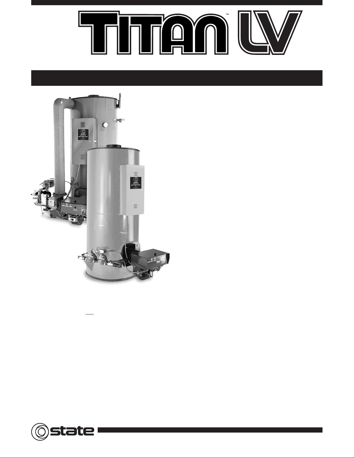
Large Volume Power Burner: Gas, Oil & Dual Fuel Commercial Water Heaters
■
Limited Warranty Outline
– If the tank should leak any time during the first three years, under
the terms of the warranty,State Water Heaters will repair or replace
heater; installation, labor, handling and local delivery extra.
– NOTE: This Outline Is NO
T A Warranty. For complete information,
consult the written warranty or State Water Heaters.
■
TPO – Oil Fired Models: No. 1 or 2 Oil
– Multi-annular fuel containment combustor head
– Available for firing light fuel oils including diesel
– Oil ignition transformer
– Integral 2-stage fuel unit
– Squirrel cage blower
– Oil safety valve
■
TPD – Dual Fuel Gas/Oil: Natural Gas or Propane & No. 1 or 2 Oil
– Multi-annular fuel containment combustor head
– Gas electric pilot and gas ignition transformer
– Pilot and main pressure regulators
– Air safety switch
– Manual fuel selector switch
– Integral 2-stage fuel unit
– Squirrel cage blower
■
Meets or exceeds current edition of ASHRAE/IES-90.1-1999.
■
Low NOX– TPX Low NOXmodels meet or exceed current Texas and
California SCAQMD air quality standards.
■
UL – Entire unit UL listed (File No. MH11631).
■
Glass-Lined Tank – Exclusive corrosion protection with glasslining on all interior surfaces. Multiple anodes provide even more
corrosion protection.
■
ASME Construction Standard – 160 PSI working pressure on all models.
■
Powered Gas Burner – Powered burner has electronic flame
safeguard control with intermittent spark ignition. Also included are
main and pilot automatic gas valves plus gas pressure regulators,
diaphragm air switch for proof of blower operation.
– TPX Low NO
X
Models are factory standard with modulating fire.
The burner automatically adjusts the firing rate and the Btu output
to maintain precise system temperature control.
■
Fully Automatic Controls With Safety Shutoff – High temperature
limit control (manual reset). ASME rated temperature and pressure
relief valve. Hinged door control compartment for ease of access.Two
thermostats, upper and lower, for accurate temperature control.
Standard control is for 120˚F - 180˚F water service.
■
Jacket And Insulation – Heavy gauge steel with baked powder coat
finish. Insulated with high-density foam insulation that meets or
exceeds all required standards.
■
Professional Start-Up Service Furnished To Assure Most Efficient
Combustion And Safe Initial Start-Up.
■
Other Features
– Two layers of high temperature ceramic fiber insulation in
combustion chamber
– Flame inspection port opening
– Mounted on rugged channel iron skids
– Combination temperature and pressure gauge
– Low water cutoff
– ASME rated temperature and pressure relief valve
– Barometric draft regulator
– Two cleanout inspection openings
– 120 volt control circuit
– Drain valve
– Removable lifting lugs
■
Options
– Factory Mutual approved control arrangement
– Industrial Risk Insurance (IRI Gas Train)
– 5 year or 10 year limited warranty
– High or low water pressure switch
– 180°F water service thermostats
– A.G.A. rated T & P Valve
– Modular graphic burner systems management on heaters with
270,000 Btu input and over
– Combustion Air intake Adapter
COMMERCIAL
The Expert’s Choice
®
Page 2
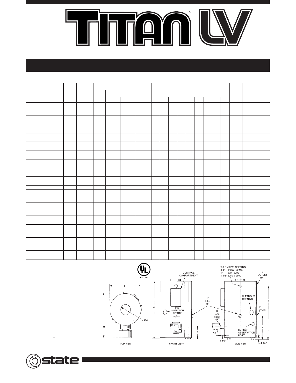
Nominal
Input
Output (Gallons)
Storage
Rating
Ship.
Model Number
Capacity
BTU/Hr.
First Recovery
Dimensions In Inches
Wt. Motor HP
U.S. Natural Hour
w/Burner 120V 60 Hz 1
Gallons Gas Rating 80°F Rise 100°F Rise 140°F Rise A B C D E F G H J
(lbs.)
TPG 150 140 NEA 150 140,000 256 170 136 97 831⁄2 141⁄2 273⁄4 11⁄4 361⁄2 5 47 73 1292
TPG 150 199 NEA 150 199,000 313 241 193 138 831⁄2 141⁄2 273⁄4 11⁄4 361⁄2 6 47 73 12921⁄7 HP - 2.5 Amps
TPG 150 255 NEA 150 255,000 367 359 247 176 831⁄2 141⁄2 273⁄4 11⁄4 361⁄2 6 47 73 1292
TPG 150 270 NEA 150 270,000 382 327 262 187 831⁄2 14 1 273⁄4 11⁄4 361⁄2 6571⁄2 73 1397
TPG 150 400 NEA 150 400,000 507 485 387 277 831⁄2 14 1 273⁄4 11⁄4 361⁄2 7571⁄2 73 13971⁄4 HP - 4.6 Amps
TPG 150 540 NEA 150 540,000 644 654 524 374 831⁄2 14 1 273⁄4 11⁄4 361⁄2 8571⁄2 73 1505
TPG 150 720 NEA 150 720,000 818 873 698 499 831⁄2 14 11⁄4 273⁄4 11⁄4 361⁄2 10 571⁄2 73 15101⁄3 HP - 5.5 Amps
TPG 200 300 NEA 200 300,000 451 364 291 208 831⁄2 15 1 321⁄2 11⁄2 443⁄4 6661⁄2 73 2098
1
⁄4 HP - 4.6 Amps
TPG 200 600 NEA 200 600,000 742 727 582 416 831⁄2 15 1 321⁄2 11⁄2 443⁄4 8661⁄2 73 2098
TPG 200 800 NEA 200 800,000 936 970 776 554 831⁄2 15 11⁄4 321⁄2 11⁄2 443⁄4 10 661⁄2 73 2103
1
⁄3 HP - 5.5 Amps
TPG 200 1000 NEA 200 1,000,000 1130 1212 970 693 831⁄2 15 11⁄4 321⁄2 11⁄2 443⁄4 10 661⁄2 73 2103
TPG 200 1250 NEA 200 1,250,000 1372 1515 1212 866 831⁄2 15 11⁄4 321⁄2 11⁄2 443⁄4 12 661⁄2 73 2467
1
⁄2 HP - 7.4 Amps
TPG 200 1500 NEA 200 1,500,000 1615 1818 1455 1039 831⁄2 15 11⁄2 321⁄2 11⁄2 443⁄4 12 811⁄2 73 2757
TPG 300 300 NEA 300 300,000 531 364 291 208 911⁄2 14 1 261⁄2 11⁄2 443⁄4 6661⁄2 83 2150
1
⁄4 HP - 4.6 Amps
TPG 300 600 NEA 300 600,000 822 727 582 416 911⁄2 14 1 261⁄2 11⁄2 443⁄4 8661⁄2 83 2150
TPG 300 800 NEA 300 800,000 1016 970 776 554 911⁄2 14 11⁄4 261⁄2 11⁄2 443⁄4 10 661⁄2 83 2308
1
⁄3 HP - 5.5 Amps
TPG 300 1000 NEA 300 1,000,000 1210 1212 970 693 911⁄2 14 11⁄4 261⁄2 11⁄2 443⁄4 10 661⁄2 83 2308
TPG 300 1250 NEA 300 1,250,000 1452 1515 1212 866 911⁄2 14 11⁄4 261⁄2 11⁄2 443⁄4 12 661⁄2 83 2584
1
⁄2 HP - 7.4 Amps
TPG 300 1500 NEA 300 1,500,000 1695 1818 1455 1039 911⁄2 14 11⁄2 261⁄2 11⁄2 443⁄4 12 811⁄2 83 2774
TPG 400 600 NEA 400 600,000 902 727 582 416 911⁄2 15 1 321⁄2 2558761⁄2 81 32071⁄4 HP - 4.6 Amps
TPG 400 800 NEA 400 800,000 1096 970 776 554 911⁄2 15 11⁄4 321⁄2 25510761⁄2 81 3212
TPG 400 1000 NEA 400 1,000,000 1290 1212 970 693 911⁄2 15 11⁄4 321⁄2 25510761⁄2 81 32121⁄3 HP - 5.5 Amps
TPG 400 1250 NEA 400 1,250,000 1532 1515 1212 866 911⁄2 15 11⁄4 321⁄2 25512761⁄2 81 3212
TPG 400 1500 NEA 400 1,500,000 1775 1816 1455 1039 911⁄2 15 11⁄2 321⁄2 25512911⁄2 81 3402
TPG 400 1750 NEA 400 1,750,000 2017 2121 1697 1212 911⁄2 15 2 321⁄2 25514911⁄2 81 35281⁄2 HP - 7.4 Amps
TPG 400 2000 NEA 400 2,000,000 2259 2424 1939 1385 991⁄2 15 2 321⁄2 25514911⁄2 89 3669
TPG 500 2250 NEA 500 2,250,000 2582 2727 2182 1558 110 15 2 321⁄2 25516911⁄2 100 4277
3
⁄4 HP - 10.2 Amps
TPG 500 2500 NEA 500 2,500,000 2824 3030 2424 1732 110 15 2 321⁄2 25516911⁄2 100 4419
TPG 600 720 NEA 600 720,000 1178 873 698 499 119 15 11⁄4 321⁄2 25510761⁄2 109 3667
TPG 600 1000 NEA 600 1,000,000 1450 1212 970 693 119 15 11⁄4 321⁄2 25510761⁄2 109 36671⁄3 HP - 5.5 Amps
TPG 600 1250 NEA 600 1,250,000 1692 1515 1212 866 119 15 11⁄4 321⁄2 25512761⁄2 109 3667
TPG 600 1500 NEA 600 1,500,000 1935 1816 1455 1039 119 15 11⁄2 321⁄2 25512911⁄2 109 3837
TPG 600 1750 NEA 600 1,750,000 2177 2121 1697 1212 119 15 2 321⁄2 25514911⁄2 109 38371⁄2 HP - 7.4 Amps
TPG 600 2000 NEA 600 2,000,000 2419 2424 1939 1385 119 15 2 321⁄2 25514911⁄2 109 3837
TPG 600 2250 NEA 600 2,250,000 2662 2727 2182 1558 119 15 2 321⁄2 25516911⁄2 109 4477
3
⁄4 HP - 10.2 Amps
TPG 600 2500 NEA 600 2,500,000 2904 3030 2424 1732 119 15 2 321⁄2 25516911⁄2 109 4619
TPG Power Gas Large Volume Commercial Water Heaters
500 Lindahl Parkway, Ashland City, TN 37015 • www.statewaterheaters.com
SPECIFICATIONS
Certified Minimum Installation Clearances to Combustibles:
Front: 18 inches
Back: 0 inches
Sides: 0 inches
Top: 5 inches
A clearance of 24 inches should be maintained from
serviceable parts such as relief valve, power burner, drain
valve and anodes (anodes are located on side above cold
water inlet).
Minimum gas supply pressure: 7 Inches W.C.
Maximum gas supply pressure: 13 Inches W.C.
TPG models are Category I appliances (Fan Assisted) and
require a negative draft. These units should only be
commonly vented with other Category I negative draft
appliances per the latest addition of the National Fuel Gas
Code. An approved/listed Type “B” venting material is
recommended. A negative draft of -0.02˝ to -0.07 is required
in the vent.
TPG models are available in both natural gas and propane. To
order propane, change the “N” to “P” in the model number.
Example: TPG 150 140 P
EA
ASME
COMMERCIAL
The Expert’s Choice
®
Page 3

TPX Power Low NOXLarge Volume Commercial Water Heaters
500 Lindahl Parkway, Ashland City, TN 37015 • www.statewaterheaters.com
Certified Minimum Installation Clearances to Combustibles:
Front: 18 inches
Back: 0 inches
Sides: 0 inches
Top: 5 inches
A clearance of 24 inches should be maintained from serviceable parts such as relief valve, power
burner, drain valve and anodes (anodes are located on side above cold water inlet).
Minimum gas supply pressure: 7 Inches W.C.
Maximum gas supply pressure: 13 Inches W.C.
TPX models are Category I appliances (Fan Assisted) and require a negative draft. These units should
only be commonly vented with other Category I negative draft appliances per the latest addition of the
National Fuel Gas Code. An approved/listed Type “B” venting material is recommended.A negative draft
of -0.02˝ to -0.07 is required in the vent.
Nominal
Input
Output (Gallons)
Storage
Rating
Model Number
Capacity
BTU/Hr.
First Recovery
Dimensions In Inches
Motor HP
U.S. Natural Hour
120V 60 Hz 1
Gallons Gas Rating 80°F Rise 100°F Rise 140°F Rise A B C D E F G H J
T
PX 150 400 NEA 150 400,000 507 485 387 277 831⁄2 14 1 273⁄4 11⁄4 54 7 571⁄2 73
1
⁄7 HP - 2.5 Amps
TPX 150 540 NEA 150 540,000 644 654 524 374 831⁄2 14 1 273⁄4 11⁄4 54 8 571⁄2 73
TPX 200 800 NEA 200 800,000 936 970 776 554 831⁄2 15 11⁄4 321⁄2 11⁄2 60 10 72 73
TPX 200 1000 NEA 200 1,000,000 1130 1212 970 693 831⁄2 15 11⁄4 321⁄2 11⁄2 60 10 72 73
TPX 200 1250 NEA 200 1,250,000 1372 1515 1212 866 831⁄2 15 11⁄4 321⁄2 11⁄2 60 12 72 73
TPX 200 1500 NEA 200 1,500,000 1615 1818 1455 1039 831⁄2 15 11⁄2 321⁄2 11⁄2 60 12 72 73
TPX 300 800 NEA 300 800,000 1016 970 776 554 911⁄2 14 11⁄4 261⁄2 11⁄2 60 10 72 83
TPX 300 1000 NEA 300 1,000,000 1210 1212 970 693 911⁄2 14 11⁄4 261⁄2 11⁄2 60 10 72 83
1
⁄3 HP - 8.6 Amps
TPX 300 1250 NEA 300 1,250,000 1452 1515 1212 866 911⁄2 14 11⁄4 261⁄2 11⁄2 60 12 72 83
TPX 300 1500 NEA 300 1,500,000 1695 1818 1455 1039 911⁄2 14 11⁄2 261⁄2 11⁄2 60 12 72 83
TPX 400 800 NEA 400 800,000 1096 970 776 554 911⁄2 15 11⁄4 321⁄2 267108481
TPX 400 1000 NEA 400 1,000,000 1290 1212 970 693 911⁄2 15 11⁄4 321⁄2 267108481
TPX 400 1250 NEA 400 1,250,000 1532 1515 1212 866 911⁄2 15 11⁄4 321⁄2 267128481
TPX 400 1500 NEA 400 1,500,000 1775 1816 1455 1039 911⁄2 15 11⁄2 321⁄2 267128481
TPX 400 1750 NEA 400 1,750,000 2017 2121 1697 1212 911⁄2 15 2 321⁄2 25514911⁄2 81
1 HP - 12.4 Amps
TPX 400 2000 NEA 400 2,000,000 2259 2424 1939 1385 991⁄2 15 2 321⁄2 25514911⁄2 89
TPX 600 1000 NEA 600 1,000,000 1450 1212 970 693 119 15 11⁄4 321⁄2 2 67 10 84 109
TPX 600 1250 NEA 600 1,250,000 1692 1515 1212 866 119 15 11⁄4 321⁄2 2 67 12 84 1091⁄3 HP - 8.6 Amps
TPX 600 1500 NEA 600 1,500,000 1935 1816 1455 1039 119 15 11⁄2 321⁄2 2 67 12 84 109
TPX 600 1750 NEA 600 1,750,000 2177 2121 1697 1212 119 15 2 321⁄2 25514911⁄2 109
1 HP - 12.4 Amps
TPX 600 2000 NEA 600 2,000,000 2419 2424 1939 1385 119 15 2 321⁄2 25514911⁄2 109
SPECIFICATIONS
ASME
COMMERCIAL
The Expert’s Choice
®
Page 4

TPO Power Oil Large Volume Commercial Water Heaters
500 Lindahl Parkway, Ashland City, TN 37015 • www.statewaterheaters.com
Actual
Input
Output (Gallons)
Storage
Rating
Ship.
Model Number
Capacity
BTU/Hr.
Firing
Recovery
Dimensions In Inches
Wt. Motor HP
U.S.
Rate
w/Burner 120V 60 Hz 1
Gallons
GPH
80°F Rise 100°F Rise 140°F Rise A B C D E F G H J
(lbs.)
TPO 150 140 OEA 163 140,000 1 170 136 97 831⁄2 14 –
273⁄4
11⁄4 361⁄2 5 47 73 1292
TPO 150 199 OEA 163 199,000 1.4 241 193 138 831⁄2 14 –
273⁄4
11⁄4 361⁄2 6 47 73 1292
1
⁄7 HP - 4.4 Amp
TPO 150 255 OEA 163 255,000 1.8 309 247 176 831⁄2 14 –
27
3
⁄4
11⁄4 361⁄2 6 47 73 1292
TPO 150 270 OEA 163 270,000 1.9 327 262 187 831⁄2 14 –
27
3
⁄4
11⁄4 361⁄2 6571⁄2 73 1397
TPO 150 400 OEA 151 400,000 2.8 485 387 277 831⁄2 14 –
273⁄4
11⁄4 361⁄2 7571⁄2 73 1397
TPO 150 540 OEA 151 540,000 3.8 654 524 374 831⁄2 14 –
273⁄4
11⁄4 361⁄2 8571⁄2 73 1505
TPO 150 720 OEA 145 720,000 5.1 873 698 416 831⁄2 14 –
273⁄4
11⁄4 361⁄2 10 571⁄2 73 15101⁄4 HP - 4.6 Amp
TPO 200 300 OEA 221 300,000 2.1 364 291 208 831⁄2 15 – 321⁄2 11⁄2 443⁄4 6661⁄2 73 2098
TPO 200 600 OEA 221 600,000 4.2 727 582 416 831⁄2 15 – 321⁄2 11⁄2 443⁄4 8661⁄2 73 2098
TPO 200 800 OEA 221 800,000 5.7 970 776 554 831⁄2 15 – 321⁄2 11⁄2 443⁄4 10 661⁄2 73 2103
TPO 200 1000 OEA 201 1,000,000 7.1 1212 970 693 831⁄2 15 – 321⁄2 11⁄2 443⁄4 10 661⁄2 73 21031⁄3 HP - 5.5 Amp
TPO 200 1250 OEA 201 1,250,000 8.9 1515 1212 866 831⁄2 15 – 321⁄2 11⁄2 443⁄4 12 661⁄2 73 2467
TPO 200 1500 OEA 201 1,500,000 10.7 1818 1455 1039 831⁄2 15 – 321⁄2 11⁄2 443⁄4 12 811⁄2 73 27573⁄4 HP - 10.2 Amp
TPO 300 300 OEA 300 300,000 2.1 364 291 208 911⁄2 14 – 261⁄2 11⁄2 443⁄4 6661⁄2 83 2150
1
⁄4 HP - 4.6 Amp
TPO 300 600 OEA 300 600,000 4.2 727 582 416 911⁄2 14 – 261⁄2 11⁄2 443⁄4 8661⁄2 83 2150
TPO 300 800 OEA 300 800,000 5.7 970 776 554 911⁄2 14 – 261⁄2 11⁄2 443⁄4 10 661⁄2 83 2308
TPO 300 1000 OEA 300 1,000,000 7.1 1212 970 693 911⁄2 14 – 261⁄2 11⁄2 443⁄4 10 661⁄2 83 23081⁄3 HP - 5.5 Amp
TPO 300 1250 OEA 300 1,250,000 8.9 1515 1212 866 911⁄2 14 – 261⁄2 11⁄2 443⁄4 12 661⁄2 83 2584
TPO 300 1500 OEA 300 1,500,000 10.7 1818 1455 1039 911⁄2 14 – 261⁄2 11⁄2 443⁄4 12 811⁄2 83 27743⁄4 HP - 10.2 Amp
TPO 400 600 OEA 411 600,000 4.2 727 582 416 911⁄2 15 – 321⁄2 2558761⁄2 81 32071⁄4 HP - 4.6 Amp
TPO 400 800 OEA 411 800,000 5.7 970 776 554 911⁄2 15 – 321⁄2 25510761⁄2 81 3212
TPO 400 1000 OEA 411 1,000,000 7.1 1212 970 693 911⁄2 15 – 321⁄2 25510761⁄2 81 32121⁄3 HP - 5.5 Amp
TPO 400 1250 OEA 411 1,250,000 8.9 1515 1212 866 911⁄2 15 – 321⁄2 25512761⁄2 81 3212
TPO 400 1500 OEA 397 1,500,000 10.7 1816 1455 1039 911⁄2 15 – 321⁄2 25512911⁄2 81 3402
TPO 400 1750 OEA 397 1,750,000 12.5 2121 1697 1212 911⁄2 15 – 321⁄2 25514911⁄2 81 35283⁄4 HP - 10.2 Amp
TPO 400 2000 OEA 397 2,000,000 14.2 2424 1939 1385 991⁄2 15 – 321⁄2 25514911⁄2 89 3669
TPO 500 2250 OEA 495 2,250,000 16 2727 2182 1558 110 15 – 321⁄2 25516911⁄2 100 4277
1 HP - 16 Amp
TPO 500 2500 OEA 495 2,500,000 17.8 3030 2424 1732 110 15 – 321⁄2 25516911⁄2 100 4419
TPO 600 720 OEA 594 720,000 5.1 873 698 499 119 15 – 321⁄2 25510761⁄2 109 3667
1
⁄4 HP - 4.6 Amp
TPO 600 1000 OEA 594 1,000,000 7.1 1212 970 693 119 15 – 321⁄2 25510761⁄2 109 3667
TPO 600 1250 OEA 594 1,250,000 8.9 1515 1212 866 119 15 – 321⁄2 25512761⁄2 109 36671⁄3 HP - 5.5 Amp
TPO 600 1500 OEA 594 1,500,000 10.7 1816 1455 1039 119 15 – 321⁄2 25512911⁄2 109 3837
TPO 600 1750 OEA 594 1,750,000 12.5 2121 1697 1212 119 15 – 321⁄2 25514911⁄2 109 38373⁄4 HP - 10.2 Amp
TPO 600 2000 OEA 594 2,000,000 14.3 2424 1939 1385 119 15 – 321⁄2 25514911⁄2 109 3837
TPO 600 2250 OEA 575 2,250,000 16 2727 2182 1558 119 15 – 321⁄2 25516911⁄2 109 4477
1 HP - 16 Amp
TPO 600 2500 OEA 575 2,500,000 17.8 3030 2424 1732 119 15 – 321⁄2 25516911⁄2 109 4619
SPECIFICATIONS
Certified Minimum Installation Clearances to Combustibles:
Front: 18 inches
Back: 0 inches
Sides: 0 inches
Top: 5 inches
A clearance of 24 inches should be maintained from
serviceable parts such as relief valve, power burner, drain
valve and anodes (anodes are located on side above cold
water inlet).
State Titan TPO models are Category I appliances
(Fan Assisted) and require a negative draft. These units
should only be commonly vented with other Category I
negative draft appliances per the latest addition of the
National Fuel Gas Code. An approved/listed Type “B” venting
material is recommended. A negative draft of -0.02˝ to -0.07
is required in the vent.
ASME
COMMERCIAL
The Expert’s Choice
®
Page 5

Actual
Input
Output (Gallons)
Storage
Rating
Ship.
Model Number
Capacity
BTU/Hr.
Firing
Recovery
Dimensions In Inches
Wt. Motor HP
U.S.
Rate
w/Burner 120V 60 Hz 1
Gallons
GPH
80°F Rise 100°F Rise 140°F Rise A B C D E F G H J
(lbs.)
TPD 150 140 ONEA 163 140,000 1 170 136 97 831⁄2 141⁄2 273⁄4 11⁄4 361⁄2 5 47 73 1292
TPD 150 199 ONEA 163 199,000 1.4 241 193 138 831⁄2 141⁄2 273⁄4 11⁄4 361⁄2 6 47 73 1292
1
⁄7 HP - 4.4 Amp
TPD 150 255 ONEA 163 255,000 1.8 309 247 176 831⁄2 141⁄2 273⁄4 11⁄4 361⁄2 6 47 73 1292
TPD 150 270 ONEA 163 270,000 1.9 327 262 187 831⁄2 14 1 273⁄4 11⁄4 361⁄2 6571⁄2 73 1397
TPD 150 400 ONEA 151 400,000 2.8 485 387 277 831⁄2 14 1 273⁄4 11⁄4 361⁄2 7571⁄2 73 1397
TPD 150 540 ONEA 151 540,000 3.8 654 524 374 831⁄2 14 1 273⁄4 11⁄4 361⁄2 8571⁄2 73 1505
TPD 150 720 ONEA 145 720,000 5.1 873 698 416 831⁄2 14 11⁄4 273⁄4 11⁄4 361⁄2 10 571⁄2 73 15101⁄4 HP - 4.6 Amp
TPD 200 300 ONEA 221 300,000 2.1 364 291 208 831⁄2 15 1 321⁄2 11⁄2 443⁄4 6661⁄2 73 2098
TPD 200 600 ONEA 221 600,000 4.2 727 582 416 831⁄2 15 1 321⁄2 11⁄2 443⁄4 8661⁄2 73 2098
TPD 200 800 ONEA 221 800,000 5.7 970 776 554 831⁄2 15 11⁄4 321⁄2 11⁄2 443⁄4 10 661⁄2 73 2103
TPD 200 1000 ONEA 201 1,000,000 7.1 1212 970 693 831⁄2 15 11⁄4 321⁄2 11⁄2 443⁄4 10 661⁄2 73 21031⁄3 HP - 5.5 Amp
TPD 200 1250 ONEA 201 1,250,000 8.9 1515 1212 866 831⁄2 15 11⁄4 321⁄2 11⁄2 443⁄4 12 661⁄2 73 2467
TPD 200 1500 ONEA 201 1,500,000 10.7 1818 1455 1039 831⁄2 15 11⁄2 321⁄2 11⁄2 443⁄4 12 811⁄2 73 27573⁄4 HP - 10.2 Amp
TPD 300 300 ONEA 300 300,000 2.1 364 291 208 911⁄2 14 1 261⁄2 11⁄2 443⁄4 6661⁄2 83 2150
1
⁄4 HP - 4.6 Amp
TPD 300 600 ONEA 300 600,000 4.2 727 582 416 911⁄2 14 1 261⁄2 11⁄2 443⁄4 8661⁄2 83 2150
TPD 300 800 ONEA 300 800,000 5.7 970 776 554 911⁄2 14 11⁄4 261⁄2 11⁄2 443⁄4 10 661⁄2 83 2308
TPD 300 1000 ONEA 300 1,000,000 7.1 1212 970 693 911⁄2 14 11⁄4 261⁄2 11⁄2 443⁄4 10 661⁄2 83 23081⁄3 HP - 5.5 Amp
TPD 300 1250 ONEA 300 1,250,000 8.9 1515 1212 866 911⁄2 14 11⁄4 261⁄2 11⁄2 443⁄4 12 661⁄2 83 2584
TPD 300 1500 ONEA 300 1,500,000 10.7 1818 1455 1039 911⁄2 14 11⁄2 261⁄2 11⁄2 443⁄4 12 811⁄2 83 27743⁄4 HP - 10.2 Amp
TPD 400 600 ONEA 411 600,000 4.2 727 582 416 911⁄2 15 1 321⁄2 2558761⁄2 81 32071⁄4 HP - 4.6 Amp
TPD 400 800 ONEA 411 800,000 5.7 970 776 554 911⁄2 15 11⁄4 321⁄2 25510761⁄2 81 3212
TPD 400 1000 ONEA 411 1,000,000 7.1 1212 970 693 911⁄2 15 11⁄4 321⁄2 25510761⁄2 81 32121⁄3 HP - 5.5 Amp
TPD 400 1250 ONEA 411 1,250,000 8.9 1515 1212 866 911⁄2 15 11⁄4 321⁄2 25512761⁄2 81 3212
TPD 400 1500 ONEA 397 1,500,000 10.7 1816 1455 1039 911⁄2 15 11⁄2 321⁄2 25512911⁄2 81 3402
TPD 400 1750 ONEA 397 1,750,000 12.5 2121 1697 1212 911⁄2 15 2 321⁄2 25514911⁄2 81 35283⁄4 HP - 10.2 Amp
TPD 400 2000 ONEA 397 2,000,000 14.2 2424 1939 1385 991⁄2 15 2 321⁄2 25514911⁄2 89 3669
TPD 500 2250 ONEA 495 2,250,000 16 2727 2182 1558 110 15 2 321⁄2 25516911⁄2 100 4277
1 HP - 16 Amp
TPD 500 2500 ONEA 495 2,500,000 17.8 3030 2424 1732 110 15 2 321⁄2 25516911⁄2 100 4419
TPD 600 720 ONEA 594 720,000 5.1 873 698 499 119 15 11⁄4 321⁄2 25510761⁄2 109 3667
1
⁄4 HP - 4.6 Amp
TPD 600 1000 ONEA 594 1,000,000 7.1 1212 970 693 119 15 11⁄4 321⁄2 25510761⁄2 109 3667
TPD 600 1250 ONEA 594 1,250,000 8.9 1515 1212 866 119 15 11⁄4 321⁄2 25512761⁄2 109 36671⁄3 HP - 5.5 Amp
TPD 600 1500 ONEA 594 1,500,000 10.7 1816 1455 1039 119 15 11⁄2 321⁄2 25512911⁄2 109 3837
TPD 600 1750 ONEA 594 1,750,000 12.5 2121 1697 1212 119 15 2 321⁄2 25514911⁄2 109 38373⁄4 HP - 10.2 Amp
TPD 600 2000 ONEA 594 2,000,000 14.3 2424 1939 1385 119 15 2 321⁄2 25514911⁄2 109 3837
TPD 600 2250 ONEA 575 2,250,000 16 2727 2182 1558 119 15 2 321⁄2 25516911⁄2 109 4477
1 HP - 16 Amp
TPD 600 2500 ONEA 575 2,500,000 17.8 3030 2424 1732 119 15 2 321⁄2 25516911⁄2 109 4619
TPD Power Dual Fuel Large Volume Commercial Water Heaters
500 Lindahl Parkway, Ashland City, TN 37015 • www.statewaterheaters.com
SPECIFICATIONS
Certified Minimum Installation Clearances to Combustibles:
Front: 18 inches
Back: 0 inches
Sides: 0 inches
Top: 5 inches
A clearance of 24 inches should be maintained from
serviceable parts such as relief valve, power burner, drain
valve and anodes (anodes are located on side above cold
water inlet).
State Titan TPD models are Category I appliances
(Fan Assisted) and require a negative draft. These units
should only be commonly vented with other Category I
negative draft appliances per the latest addition of the
National Fuel Gas Code. An approved/listed Type “B” venting
material is recommended. A negative draft of -0.02˝ to -0.07
is required in the vent.
ASME
COMMERCIAL
The Expert’s Choice
®
Page 6

Large Volume Power Burner: Gas, Oil & Dual Fuel Commercial Water Heaters
Printed in U.S.A.
STPBGODF/1003
©2003 State Water Heaters
In keeping with our policy of continuous product improvement,
specifications are subject to change without prior notice.
500 Lindahl Parkway, Ashland City, TN 37015 • www.statewaterheaters.com
SUGGESTED SPECIFICATIONS
TITANTMLV POWER LOW NOX(MODELS TPX)
Water heater(s) shall be Model___________________as manufactured by State Water Heaters or an approved equal. Water heater(s) shall be of glass-lined design
and include a powered gas burner with electronic flame safeguard, intermittent ignition, main and pilot automatic gas valves,redundant solenoid gas valve, gas pressure
regulator, diaphragm air switch for proof of blower operation, and flame inspection port. Maximum supply gas pressure to heater 13˝ W.C. Heater(s) shall have an input
rating of ____________ and a recovery rating of ________ GPH at a temperature rise of 100°F with a minimum actual storage capacity of ________. Heater(s) shall
be equipped with _______ NPT water inlet and outlet openings, (2) 3˝ handhole cleanouts, shall have an ASME working pressure of 160 psi, ASME stamped and listed
by Underwriters Laboratories. The water heater shall be approved for low NOx and meet or exceed California rule 1146.2. The unit shall provide modulating fire for
smooth system operation and precise temperature control. Controls shall include: high temperature limit control (manual reset),upper and lower thermostats, modulating
control, combination temperature and pressure gauge, low water cutoff, ASME rated temperature relief valve, drain valve and draft regulator. Control compartment door
shall be hinged for easy access. The heater(s) shall be equipped with multiple anodes for cathodic protection. The heater(s) shall be insulated with high-density foam
insulation. Heater(s) must meet or exceed current ASHRAE/IES 90.1-1999 for recovery efficiency and standby loss. The outer jacket shall have a baked powder coat
finish. All internal surfaces of the heater(s) exposed to water shall be glass-lined with an alkaline borosilicate, nickelous oxide composition that has been fused to steel
by firing at a temperature range of 1400°F to 1600°F. Heater(s) tank shall have a 3, 5, or 10 year limited warranty against corrosion as outlined in the written warranty.
Professional start-up service to be included.
SUGGESTED SPECIFICATIONS
TITANTMLV POWER OIL AND DUAL FUEL (MODELS TPO AND TPD)
Water heater(s) shall be Model_____________________as manufactured by the State Water Heaters or an approved equal. Heater(s) shall have a minimum oil firing
rate of_____gallons per hour, an input rating of____________BTU/HR. The heater(s) shall have a recovery rate of_____GPH at a 100°F rise and a storage capacity
of______gallons. The 160 psi design pressure tank shall be glass-lined with an alkaline borosilicate composition and fused to the steel by firing at 1600°F. The heater(s)
shall be equipped with______NPT water inlet and outlet openings, (2) 3˝ handhole cleanouts, and carry a National Board stamping.The heater(s) shall be ASME and the
entire unit listed by Underwriters Laboratories. Controls shall include: high temperature limit control (manual reset), upper and lower thermostats, combination
temperature and pressure gauge, low water cutoff, ASME rated temperature and pressure relief valve, and barometric draft regulator. Control compartment door shall
be hinged for easy access and include cam locks for security. The heater(s) shall be equipped with multiple anodes for cathodic protection. The heater(s) shall be
insulated with high-density foam insulation and meet or exceed current standard of ASHRAE 90.1-1999 for standby loss and recovery efficiency. The heater(s) shall
include a drain valve and flame observation port. The jacket shall be baked powder coat finish. Heater(s) vessel shall have a 3, 5 or 10 year limited warranty against
failure as outlined in the written warranty.
The TPO models shall have a UL listed burner with two-stage pump, oil safety valve, electronic flame safeguard, intermittent ignition and diaphragm air switch for proof
of flame operation.
The TPD models shall include a dual fuel burner with two-stage oil pump, oil safety valve, electronic flame safeguard, intermittent ignition, diaphragm air switch, main
and pilot automatic gas valves, gas pressure regulator and manual crossover switch.
SUGGESTED SPECIFICATIONS
TITANTMLV POWER GAS (MODELS TPG)
Water heater(s) shall be Model___________________as manufactured by State Water Heaters or an approved equal. Water heater(s) shall be of glass-lined design
and include a powered gas burner with electronic flame safeguard, intermittent ignition, main and pilot automatic gas valves,redundant solenoid gas valve, gas pressure
regulator, diaphragm air switch for proof of blower operation, and flame inspection port. Maximum supply gas pressure to heater 13˝ W.C. Heater(s) shall have an input
rating of ____________ and a recovery rating of ________ GPH at a temperature rise of 100°F with a minimum actual storage capacity of ________. Heater(s) shall
be equipped with _______ NPT water inlet and outlet openings, (2) 3˝ handhole cleanouts, shall have an ASME working pressure of 160 psi, and stamped National
Board, and listed by Underwriters Laboratories. Controls shall include: high temperature limit control (manual reset), upper and lower thermostats, combination
temperature and pressure gauge, low water cutoff, ASME rated temperature relief valve, drain valve and draft regulator. Control compartment door shall be hinged for
easy access. The heater(s) shall be equipped with multiple anodes for cathodic protection. The heater(s) shall be insulated with high-density foam insulation. Heater(s)
must meet or exceed current ASHRAE/IES 90.1-1999 for recovery efficiency and standby loss. The outer jacket shall have a baked powder coat finish. All internal
surfaces of the heater(s) exposed to water shall be glass-lined with an alkaline borosilicate, nickelous oxide composition that has been fused to steel by firing at a
temperature range of 1400°F to 1600°F. Heater(s) tank shall have a 3, 5, or 10 year limited warranty against corrosion as outlined in the written warranty. Professional
start-up service to be included.
COMMERCIAL
The Expert’s Choice
®
 Loading...