

Statebourne cryogenics Biosystem Access, Biosystem Archive, Biosystem 12, Biosystem 24, Biosystem 50 User Manual
...
User Manual
Biosystem Series
Tel: +44 (0) 191 416 4104 Fax: +44 (0) 191 415 0369 Email: info@statebourne.com
Biosystem Access Series Biosystem 12
Biosystem 24
Biosystem 50
Biosystem Archive Series Biosystem 36
Biosystem 40
Biosystem 45
Biosystem 55
Biosystem 60
Biosystem 80
Biosystem 100
Biosystem 100 Plus
18 Parsons Road,
Parsons Industrial Estate,
Washington, Tyne and Wear
NE37 1EZ
STA TEBOURNE
cryogenics
Electronic Set-up and Installation

CONTENTS
SAFETY 4
INTRODUCTION 6
CONNECTION TO LIQUID NITROGEN SUPPLY 7
INITIAL FILL WHEN USING LIQUID PHASE SETTINGS 7
DESCRIPTION OF LEVEL CONTROLLER COMPONENTS 8
CONTROLLER INSTALLATION 10
INITIAL SETTING UP 10
SYSTEM SETUP PROCEDURE 11
CLOCK SETTINGS - READJUSTMENT 17
NORMAL OPERATION 17
ALARM REPORTING 17
TESTING 18
SYSTEM FAULTS 19
DATA LOGGING 20
PRINTING THE DATA LOG 20
CLEARING THE DATA LOG 23
DATA RECOVERY 24
DOWNLOADING DATA TO A PC 24
TEMPERATURE RECORDER OUTPUT 24
SIMULTANEOUS FILLING 25
REMOTE ALARM CONNECTION 25
AUXILIARY RELAY 25
24V AC OUTPUT 25
Page 2

Appendix A 26
SENSOR POSITIONING
Appendix B 28
OPTION SWITCH SETTINGS
Appendix C 31
CONNECTION TO A PRINTER/PC
Appendix D 32
CALIBRATION OF TEMPERATURE READOUT
Appendix E 33
SIMULTANEOUS FILL CONNECTION
Appendix F 34
ALARM CODES/TROUBLESHOOTING
Appendix G 35
MAINTENANCE
Appendix H 36
REPLACEMENT PARTS
MANUAL REVISION INDEX AND APPROVAL
37
Page 3

SAFETY
Introduction
In all cryogen handling the following appropriate safety guidelines are essential if damage to equipment and
personal injury are to be avoided. The following guidelines provide a basic level of instruction in the precautions
necessary but are by no means exhaustive, a comprehensive approach involving staff training on a recognised
course is strongly recommended.
Liquid Nitrogen
The boiling point of liquid nitrogen is -196°c (77K).
The molecular weight of nitrogen is 28.
Nitrogen gas is inert, odourless, tasteless and colourless.
Nitrogen gas is an asphyxiant.
Liquid nitrogen is odourless, colourless, slightly lighter than water and does not produce toxic or irritating
vapours.
Hazards and Precautions
Cryogenic Burns
Appropriate protective clothing should always be worn when handling cryogenic equipment.
The extreme cold can cause cryogenic burns which have a similar effect on the skin to frostbite.
Similar methods should be used in the treatment of both.
Re-warm the affected area as quickly as possible in WARM water at about 40°c or by warm air.
Maintain general body warmth.
Do not rub or massage the affected area as this may cause more serious damage than already exists.
Seek medical advice as soon as possible.
Oxygen Depletion
Liquid nitrogen should always be stored and used in well ventilated areas and the use of oxygen deficiency
monitors is strongly recommended.
Liquid nitrogen expands when vaporised into a gaseous state by a factor of 842 times, causing a significant
danger from asphyxiation in confined or poorly ventilated spaces. Suffocation can occur rapidly as the oxygen is
displaced. (A drop of only 2% in the oxygen content is enough to pose a significant risk.)
Loss of consciousness or dizziness while working with liquid nitrogen are obvious signs of asphyxiation due to
an oxygen deprived atmosphere. At the first signs of this the subject should be moved as quickly as possible
from the affected area. If breathing has stopped apply artificial respiration and summon medical assistance
immediately.
Condensed Air
Due to extreme cold, air on the outside of transfer hoses and dewars can condense and form liquid air.
Adequate ventilation should ensure that any risk from this occurring is minimised. However, as with liquid
oxygen a strict no smoking or naked flame rule must be observed.
Page 4

Protective Equipment
Cryogloves
The wearing of a suitable pair of gloves is essential for day to day operations with liquefied gases.
Gloves generally fall into two categories. Those for handling objects in cold gas vapours are usually gauntlets of
mid-arm or shoulder length. For handling liquid dispensing hoses and tanks, heavy duty leather wrist length
gloves can be used.
Face Shields
Clear visors are available to protect eyes and face from liquid splashes.
Aprons
Thermal aprons can also be worn to protect against liquid splashes.
Footwear
Appropriate safety footwear should be worn at all times. Lightweight footwear and open sandals are not
recommended for obvious reasons. Wellington or loose fitting boots should be tied at the top to ensure that no
liquid can enter. For best protection use only approved safety footwear.
Oxygen Deficiency Monitors
Analysis of the oxygen content in an atmosphere is often overlooked but can be one of the most fundamental
safety measures. A monitor can provide a constant analysis and thus increase safety.
All of the above safety equipment is available from Statebourne’s Customer Service Department who
will be pleased to help with any queries you might have.
Page 5

INTRODUCTION
All Biosystem Series refrigerators utilise the M265CE microprocessor based liquid nitrogen level controller.
The M265CE will perform the following functions.
*Level monitoring and automatic filling of refrigerators.
*Level display (High/Normal/Low).
Temperature monitoring and display.
Generation of local and remote alarms for:
High Temperature
Underfilled
Overfilled
Sensor faults
Failure of liquid nitrogen supply
Lid left open.
*Manual filling.
*Chart recorder output.
*Logging of temperature, levels, alarms, fill activity etc.
*Serial port for printer output of logged data.
*Self testing and isolation of sensor faults.
*Lid open detection.
*Simple “daisy chaining” of controllers for simultaneous filling in multiple installations.
*Automatic defogging on lid opening. n
*Fast temperature recovery on lid closure. (‘Quick Chill’). n
*Communication with PC for downloading of data.
n These functions will be disabled if a fill delay switch is fitted.
Fill delay switch will only be fitted if specifically requested where, for example, automatic venting of the
nitrogen supply pipework is incorporated to allow for gas produced during cool down to be prevented from
blowing through the Biosystem.
Page 6

CONNECTION TO LIQUID NITROGEN SUPPLY
The Biosystem Series refrigerators should be supplied with liquid nitrogen ONLY, from a liquid cylinder or bulk
tank operating at between 10psiG and 20psiG maximum.
Operating pressures in excess of this will increase transfer losses and could cause the liquid level in the sensor
tube to fluctuate and send false signals to the controller, thus causing the refrigerator to underfill.
If the supply pressure were to exceed the lifting pressure of the Biosystem’s own relief devices the entire
contents of the supply vessel could be discharged, causing a hazard in the area of the refrigerator and
dramatically increasing operating costs.
The liquid fill connection on the refrigerator is ½”BSPP female and incorporates a filter and in-line relief valve
which should not be removed or by-passed while in service.
Before connecting to the Biosystem refrigerator the supply hose and, where applicable the super insulated
vacuum line should be thoroughly purged with warm nitrogen gas to remove any moisture which may
contaminate the seats of the solenoid valves or sensor probes with ice particles. Connections should be free
from grease and dirt and checked for leaks.
To minimise transfer losses, supply lines should be kept as short as possible and insulated with a suitable
material.
A shut off valve from the supply vessel should be located close to the Biosystem refrigerator for use in
emergencies and for maintenance purposes. Care should be taken to include a suitable pressure relief device
between any two shut off valves as any liquid trapped in the line will expand by more than 800 times as it
warms up and could burst the pipe or fracture one of the couplings.
INITIAL FILL
Important:-
The initial fill must be carried out with the lid open in order to avoid possible permanent
damage to the lid assembly.
When filling a warm vessel to operate in liquid phase, the fill should be carried out in stages due to the massive
amounts of cold gas formed which could cause ice build ups around the venting area at the rear of the vessel
which is in the proximity of the thermocouple. Ice build up in this area could cause damage to the thermocouple
when the lid is opened and so is to be avoided.
The initial liquid phase fill on a Biosystem 24 for example will take about 3 hours if allowed to fill continuously. It
is strongly recommended that the refrigerator is allowed to fill in cycles of about one hour with intervals of one
hour in between to allow the vessel to settle.
Page 7

DESCRIPTION OF LEVEL CONTROLLER COMPONENTS
The M265CE System consists of the following items:-
Controller (M266CE) _ Part Number 8601044
Connector PCB + Cable Assembly (M267CE) _ Part Number 8601045
Sensor Assembly with Thermocouple (M268CE) _ Part Number 8601046
Safety Transformer (M269CE) _ Part Number 8601973
M265CE Controller
The Control panel features four function keys, Alarm, Level and Fill LEDs, and a 3 digit LED display. (Fig 1.).
The digital display indicates the temperature within the refrigerator and in conjunction with the function keys
may be used to read and alter the systems settings.
In Alarm conditions the Alarm LEDs indicate the nature of the fault. The digital display gives additional
information by means of alarm codes.
Level is indicated by 3 LEDs as High, Low or Normal and at the extremes by means of Overfill and Low level
alarm LEDs.
A Fill LED indicates when the refrigerator is being filled.
M267CE Connector PCB
This provides two part screw terminal connectors for all external cables. A single, plug in 20 way ribbon cable
links the controller to the connector PCB.
This arrangement allows the gland plate and external cables to be connected to, or removed from the
refrigerator without disturbing any permanent connections.
M268 Sensor Assembly
This is the 4 level Thermistor Sensor Assembly with Thermocouple.
M269CE Safety Transformer
This supplies power at 24V AC to operate the controller.
Page 8

Page 9

CONTROLLER INSTALLATION
The Controller will normally be installed by the manufacturer of the Refrigerator.
If installing the Controller check that the option switches are correctly set for the installation. These are located
just behind the display, on the Controller PCB.
Details of the options and switch settings are given in Appendix B.
INITIAL SETTING UP
If a printer is to be used set it up and connect to the 9 way D type connector on the gland plate at the rear of the
refrigerator and change S5 to the off position (see Appendix B). For cable details and printer settings see
Appendix C.
Switch on the printer.
Printer connection
The sensor positions are pre-set in the factory to suit Statebourne’s inventory control systems (vapour phase or
liquid phase depending on order specification). See Appendix A for details.
Plug the M269CE Safety Transformer into the mains supply and switch on.
The audible alarm may sound even if the refrigerator has been filled. Use the Mute switch to silence the
audible alarm.
If the refrigerator is empty or the LN2 level is low the refrigerator will begin to fill. Further alarms may occur and
these may be silenced using the Mute switch. Ignore any alarm messages for the time being.
When the refrigerator has finished filling the controller must be initialised.
To do this switch off the power to the refrigerator, then switch on the power whilst pressing and holding the
secret key. The alarm will sound three times and the following message will appear.
Release the switch. If a printer is connected it should record the time power was restored and a System Reset.
Page 10

After a couple of seconds the digital display will show the temperature and the Level LEDs will show the Level.
The temperature readout is calibrated at the factory and should be correct. If not, it may be re-calibrated as per
Appendix D.
After initialisation the System Set-up should be carried out.
Two set-up modes are possible:
a) Defaults are Enabled by means of the DIL switch. Only the alarm temperature, refrigerator no. and
time/date need to be entered.
b) Defaults are not Enabled. All alterable parameters must be entered.
Note that the following description of the system set-up procedure assumes that the default settings are not
enabled.
SYSTEMS SETUP PROCEDURE
To enter the set-up routine press the Mute and Test keys simultaneously.
The controller will bleep twice and the Version No. of the Controller firmware will be displayed.
Temperature Alarm
After a short time the Temperature LED will light and a temperature will be displayed on the digital display.
This is the alarm temperature.
Use the TEST key to decrease the alarm temperature.
Use the MUTE key to increase the temperature.
The Alarm Temperature is adjustable in 5 degree steps between 0 and -150 C.
If the temperature of the Thermocouple rises above this pre-set the value an alarm condition will occur.
Press the FILL key when finished.
Page 11

Fill Timer
The LN2 SUPPLY LED will light and a number will be displayed. This is the Fill Timer setting in minutes.
Use the TEST key to increase the Fill Timer setting.
Use the MUTE key to decrease the Fill Timer setting.
The Fill Time is adjustable in 5 minute steps between 0 and 125 minutes.
If the solenoid valve is operated for longer than this pre-set time an alarm condition will occur.
Press the FILL key when finished.
Remote Alarm Timer
The REMOTE LED will light and a number will be displayed.
This is the Remote Alarm Timer setting in minutes.
Use the TEST key to increase the Remote Alarm Timer setting.
Use the MUTE key to decrease the Remote Alarm Timer setting.
The Remote Alarm Timer is adjustable in 5 minute steps between 0 and 60 minutes.
The Remote Alarm Timer sets the time which must elapse between the first alarm condition and activation of
the remote alarm relay. The exception to this is the Overfill alarm which defaults to 5 minutes irrespective of the
Remote Timer setting.
Press the FILL key when finished.
Lid Timer
The LID LED will light and a number will be displayed. This is the Lid Timer setting in minutes.
Use the TEST key to increase the Lid Timer setting.
Use the MUTE key to decrease the Lid Timer setting.
The Lid Timer is adjustable in 5 minute steps between 0 and 30 minutes.
Page 12

The Lid Timer sets the maximum time that the lid may be left open before the alarm sounds. Note that a lid
switch must be fitted to utilise this option.
Press the FILL key when finished.
Defog Timer
The digital display will show (e.g.)
(‘d’ indicates Defog time.)
(number is time in seconds.)
When the lid is opened, liquid nitrogen is allowed into the refrigerator for the pre-set number of seconds.
This has the effect of dispersing the fog within the vessel.
Use the TEST key to increase the Defog Timer setting.
Use the MUTE key to decrease the Defog Timer setting.
The Defog Timer is adjustment in 5 second steps between 0 and 90 seconds.
Note that a lid switch must be fitted if this function is required.
If a lid switch is fitted but the Auto Defog feature is not required, set the time to 00 sec.
Press the FILL key when finished.
Chill Timer
The digital display will show (e.g.)
When the lid is closed, liquid nitrogen is allowed into the refrigerator for the pre-set number of seconds. This
has the effect of rapidly restoring the temperature of the vessel on lid closure.
Use the TEST key to increase the Chill Timer setting.
Use the MUTE key to decrease the Chill Timer setting.
Page 13
(‘C’ indicates Chill time.)
(number is time in seconds.)

The Chill Timer is adjustable in 5 second steps between 0 and 90 seconds.
Note that a lid switch must be fitted if this function is required.
If a lid switch is fitted but the Chill feature is not required, set the time to 00 sec.
Press the FILL key when finished.
Refrigerator Number
The digital display will show (e.g.)
(‘r’ indicates Refrigerator No.)
This number will be printed in the page headings of the data log when it is printed out. A unique number should
be chosen for each refrigerator so that printouts from different refrigerators may be identified.
If the refrigerator is linked to a PC it will only respond to commands which contain the correct refrigerator
number (unless set to 00).
Use the TEST key to increase the Refrigerator No.
Use the MUTE key to decrease the Refrigerator No.
The refrigerators No. is adjustable between 00 and 99.
Press the FILL key when finished.
Clock Setting
Display will show (e.g.)
Use the TEST key to increment the date.
Use the MUTE key to decrement the date.
Page 14
(‘d’ indicates day of month)

Press the FILL key when finished.
(
)
Display will show (e.g.):
Use the TEST key to increment the month.
Use the MUTE key to decrement the month.
Press the FILL key when finished.
Display will show (e.g.):
Use the TEST key to increment the year.
Use the MUTE key to decrement the year.
Press the FILL key when finished.
Display will show (e.g.):
(month)
(‘y’ indicates year)
(‘H’ indicates hour.)
24 hr clock.
Use the TEST key to increment the hour.
Use the MUTE key to decrement the hour.
Press the FILL key when finished.
Display will show (e.g.):
(minute.)
Use The TEST key to increment the minute.
Page 15

Use the MUTE key to decrement the minute.
Press the FILL key when finished.
Log Interval
Display will show (e.g.):
(‘L’ indicates Log Interval)
The logging interval is selectable from 5, 10, 15, 30, 60 minutes or 2, 4, 6, 12, 24 hrs or No Logging.
At each logging point the Time and date, Temperature and Level are recorded. If filling is in progress this is
also recorded.
Use the TEST key to increase the Logging Interval.
Use the MUTE key to decrease the Logging Interval.
Set the interval to 00 if no logging is required.
Press the FILL key when finished.
A long beep will be heard and the digital display will revert to its temperature display mode.
This concludes the Set-up Procedure.
Assuming that all is in order and sensible timer and temperature settings have been selected the alarm lamps
and audible alarm should be off.
Page 16

CLOCK SETTINGS - READJUSTMENT
Follow the same procedure as in the System Set-up Procedure, skipping over the timer settings etc.
It is suggested that the clock is left to GMT. If it is adjusted for BST there will be overlaps or gaps in the data
log when the hourly change is made.
Periodically the clock should be checked for accuracy. If adjustment is found to be necessary try and avoid
doing this close to a logging point for the same reason as above.
NORMAL OPERATION
During normal operation of the unit the digital Display shows the temperature of the Thermocouple and the
Level LEDs show the liquid relative to the sensors. The level LEDs operate in a ‘bar graph’ mode. See
appendix A for the correspondence between the liquid level and LED display.
Filling takes place automatically to compensate for evaporative losses.
The FILL switch may be used to top up the liquid level or for defogging the chamber.
When the Fill solenoid is active the green Fill LED is illuminated.
ALARM REPORTING
If an alarm condition occurs the audible alarm will sound and an alarm lamp will flash.
The audible alarm may be silenced by pressing the Mute switch.
If an alarm is ‘muted’ the alarm lamp will stop flashing but will remain lit while the alarm is present.
Pressing the Mute switch also causes an appropriate alarm code to be displayed on the digital display.
If more than one alarm condition has occurred (eg. High Temperature and Lid Open) the alarm codes will be
displayed in sequence.
The Mute switch is used to toggle the display between Temperature readout and Alarm reporting.
If new alarm conditions occur they will reactivate the audible alarm.
Page 17

After a pre-set period from the first alarm the Remote Alarm relay will be de-energised, the audible alarm will be
reactivated and the REMOTE LED will flash. This may be muted in the same way as the other alarms.
Clearing the alarm conditions will switch off the relevant alarm LEDs and audible alarm, re-energise the Remote
Alarm relay and return the display to Temperature readout mode.
If a printer is connected to the Controller it is monitored continuously in case it becomes disconnected or runs
out of paper.
If this happens an alarm will be generated but no alarm lamp will be hit. The nature of the fault can be
ascertained by using the mute switch and obtaining the alarm code.
A list of the alarm codes is given in Appendix F.
TEST FUNCTIONS
The TEST key allows testing of the controller and the Remote Alarm.
To activate the test routine press and hold the TEST key.
The sounder will bleep twice and the following message will be displayed:-
After another couple of seconds all of the LEDs except the SYSTEM LED will light and the digital display will
read 8.8.8.
Keep the test key pressed.
After a few more seconds the panel LEDs will go out.
Keep the test key pressed.
After a few more seconds the alarm will sound.
Release the test key.
The Remote LED will start to flash. After a few seconds the Remote Alarm relay will drop out.
After a few more seconds the Remote Alarm LED will go out, the audible alarm will cease and the Remote
Alarm relay will be re-energised.
No logging or Reporting of the test will occur.
If the TEST key is released before the audible alarm sounds the Remote Relay test will not be performed.
Page 18

SYSTEM FAULTS
If a fault disrupts the operation of the controller and it fails to restart itself correctly the SYSTEM LED will flash
and the alarm will sound. The Remote Alarm may also be de-energised.
If this occurs the controller should be reinitialised by performing a System Reset as described in the section on
Initial Setting Up. Note that all stored data will be lost in this operation and logging will be disabled and must be
re-programmed if required.
If the Controller still fails to function Correctly a Service Engineer should be called.
It may be possible to restore limited function to a faulty Controller by putting it into a ‘reset’ condition. In this
state it will maintain the liquid level between the high and low sensors but levels, temperatures and alarms will
not be monitored or logged. The LEDs and temperature readout will be frozen and should be ignored.
The Controller may be forced into the Reset state by transferring the link on LK2 (next to the sounder) to the
RESET position on LK1. It will be necessary to remove the Controller from the refrigerator cabinet and remove
the white cover from the PCB to do this. This link change will also silence the audible alarm.
If the behaviour of the Controller is still unsatisfactory it should be left switched off at the front panel. The
Manual Fill switch on the Connector PCB may be used to top up the liquid level pending a service call.
Page 19

DATA LOGGING
Data logging can take two forms:-
1) Printer permanently connected.
At the pre-set intervals a status is sent to the printer. Events such as filling and lid opening are reported as they
occur. Alarms are also reported as they occur.
If required, the entire data log can be printed on demand.
2) Printer not permanently connected.
The data log is stored, but only printed out on demand. Up to 3100 ‘events’ may be logged and stored in
memory. As an example, if a 15 minute logging interval is selected, Downloading to a printer will be required
approximately once per month.
If logged data is critical more regular downloading or continuous logging as in 1) is recommended.
PRINTING THE DATA LOG
Four different print options are provided. These are:-
DATA LOG - Time, Date, Temperature, and Level for each logging point are listed line by line. Alarms and
other events are also listed.
TEMPERATURE LOG - Time and temperature only are listed for each logging point. The information is
arranged into columns and grouped in days with a new header with date for each day.
ALARM LOG - As DATA LOG but only alarms, resets and power on/off events are listed.
FILL ACTIVITY LOG - As data log but only Fill On and Fill Off events are listed.
Before printing out ensure the printer is connected, switched on and has sufficient paper to print all of the
expected data (up to 60 sheets of A4)
For printer connection details see Appendix C.
Page 20

To access the printer routine press the MUTE and SECRET keys simultaneously. The following message will
appear.
Press the FILL switch and the display will change to:-
(Data Log.)
PRESS AND HOLD the TEST switch to print the Data Log (There will be a bleep followed by a gap and 3
further bleeps before printing commences).
Or…
Press the FILL switch to select the next option.
If the FILL switch is pressed the display will change to:-
(Temperature Log.)
PRESS AND HOLD the TEST switch to print the Temperature Log (There will be a bleep followed by a gap and
3 further bleeps before printing commences).
Or…
Press the FILL switch to select the next option.
If the FILL switch is pressed the display will change to:-
(Alarm Log.)
PRESS AND HOLD the TEST switch to print the Alarm Log (There will be a bleep followed by a gap and 3
further bleeps before printing commences).
Or…
Press the FILL switch to select the next option.
If the FILL switch is pressed the display will change to:-
Page 21

(Fill Activity Log.)
PRESS AND HOLD the TEST switch to print the Fill Activity Log
(There will be a bleep followed by a gap and 3 further bleeps before printing commences).
Or…
Press the FILL switch to select the next option.
If the FILL switch is pressed (i.e. No print options have been selected) the display will change to:-
(Clear Data Log.)
(See the section on Clearing the Data Log)
Press the FILL switch the display will change to:-
(Data Recovery.)
(See the section on Data Recovery)
Press the FILL switch to return to the temperature display.
If any of the print options are selected the digital display will return to its temperature readout mode and printing
will continue until complete. During printing the Controller will function as normal though logging will be
temporarily suspended.
At the end of printing the sounder will give one long bleep.
If the printer becomes unavailable while printing is in progress, an alarm will be activated.
Page 22

CLEARING THE DATA LOG
Once the data log has been successfully printed it may be cleared. Note that clearing the log does not erase
any data. It merely sets a pointer in the memory to tell the printer where to start the next printout.
The DATA RECOVERY option may be used to retrieve data even after it has been cleared.
Data is only lost when all 3100 records have been filled at which point the oldest records are overwritten.
To clear the data log:
Enter the Printer menu by pressing the MUTE and SECRET keys simultaneously.
Use the FILL key to work through the printer menu until the display reads:-
Press and hold the TEST Switch.
The sounder will give one bleep followed by a delay and a further three bleeps, then the following message will
appear.
The data log is now cleared.
Page 23

DATA RECOVERY
To Recover the data log:
Enter the Printer menu by pressing the MUTE and SECRET keys simultaneously.
Use the FILL key to work through the printer menu until the display reads:-
(Data Recovery.)
Press and hold the TEST Switch.
The sounder will bleep once and the display will change to:-
This is the start of the printer menu. Either print out the recovered data as described previously or press the
SECRET key to revert to normal operation.
DOWNLOADING DATA TO A PC
As an alternative to printing a log, stored data may be downloaded to a PC. Software can be supplied for this
purpose. Alternatively, if users wish to write their own software, details of the PC interface can be supplied.
TEMPERATURE RECORDER OUTPUT
As an alternative to (or as well as ) a printed data log a chart recorder may be connected.
The output is taken from the terminals marked REC + and - on the connector PCB. Pass the recorder cable
through a spare cable gland and strip and terminate to the Recorder terminal block.
Output is -10mV/C over the range 0 to -200 C. i.e. 1.96V at -196 C. Output resistance is 1K ohms approx.
Page 24

SIMULTANEOUS FILLING
Where two or more refrigerators are connected to the same Liquid Nitrogen supply, economies in the use of
Nitrogen may be realised by synchronising the filling of refrigerators. This reduces the number of fill cycles
required and hence the losses due to nitrogen being trapped in the common supply pipework and vented at the
end of a fill cycle.
To use this feature connect the EXT FILL terminals of the refrigerators using 2 core cable, ensuring that + is
connected to + and - to-. (See Appendix G).
Whenever a refrigerator in the connected group starts to fill a signal is sent to all of the others. This causes
them to start a fill cycle if they are not already full.
Up to 20 refrigerators may be connected together in this way.
Make sure however that the supply pressure is adequate to complete filling in a responsible time. If not, a
supply alarm may be generated by one or more of the controllers. For large installations it may be better to
connect the refrigerators in two or more groups. The best groupings will depend upon pipework layout.
REMOTE ALARM CONNECTION
A changeover relay contact is provided to facilitate reporting of an alarm condition at a point remote from the
refrigerator.
In the ‘good’ condition the relay is energised. i.e. the Normally Open (NO) contact is closed and the Normally
Closed (NC) contact is open.
If the remote alarm is activated or there is a power failure the relay is released and the contact changes over.
For safety reasons the relay should switch no more than 2 Amps at 50V AC/DC. (Resistive load).
AUXILIARY RELAY
To cater for possible additional or special functions an auxiliary relay is provided. It is not used in this version of
the software.
24V AC OUTPUT
Up to 0.5 Amps may be drawn from this output. It may be used for example to power a lamp or siren from the
remote alarm contact.
A suitable rated fuse (0.5A max) should be inserted in F2 if this feature is required.
Do not exceed 0.5 Amps as this may overload the M269CE safety transformer.
Page 25

APPENDIX A
SENSOR POSITIONING
The position of the sensors in the sensor tube determines the level of Liquid Nitrogen to be maintained.
The longest lead with a single sensor pod is the low level sensor assembly. The upper bead in the pod is the
Low sensor and the lower bead is the Extra Low Sensor.
The lead with two pods is the high level sensor assembly, consisting of the High and Extra High Sensors.
The Low and High sensors must be separately positioned to set the liquid levels at which the controller will start
and terminate each fill cycle. The position of the High sensor determines the maximum depth of liquid in the
vessel.
The thermocouple is normally set to sense the temperature under the lid but may be positioned anywhere in the
refrigerator within the limits of its length.
Determination of the liquid level to be maintained and positioning of the thermocouple depends on the
application and the product being stored, and is beyond the scope of this manual.
Page 26
A-1
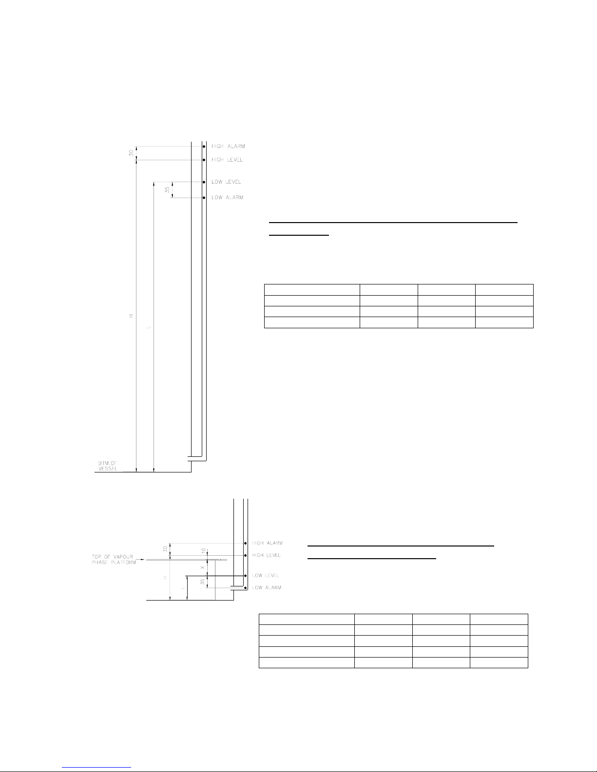
The sensor positions are set in the factory prior to despatch to suit standard Statebourne inventory control
systems (liquid or vapour phase) or can be set at any height in between to customers own specification,
although the height between each sensor is fixed and cannot be altered.
Standard Statebourne liquid phase ICS/level sensor heights –
Access Series.
This is the maximum liquid depth that can be
achieved and the sensors should not be raised
any higher otherwise damage to the lid may occur.
BM12 BM24 BM50
DIM H (mm)/VOL (L) 595/178 685/334 760/760
DIM L (mm)/VOL (L) 545/163 635/310 725/725
VOL.PER FILL (L) 15 24 35
Standard Statebourne vapour phase ICS/level
sensor heights – Access Series.
This is the minimum liquid depth that can be
achieved and lowering of the sensors should not
be attempted.
BM12 BM24 BM50
DIM X (mm) 40 40 25
DIM H (mm)/VOL (L) 110/33 110/53 150/150
DIM L (mm)/VOL (L) 60/18 60/29 115/115
VOL.PER FILL (L) 15 24 35
A-2
Page 27

The Biosystem Archive Series which have revolving turntables are factory set to fill to the levels shown below.
Because the turntable is a sealed unit this means that these are all vapour phase settings. Other settings
including liquid phase are available upon request.
BM36
9916063
DIM A (mm) 405 405 355 355 355 355 355
HIGH LEVEL VOL (L) 184 193 225 236 260 281 300
LOW LEVEL VOL (L) 159 168 172 183 207 228 247
VOL PER FILL (L) 25 25 53 53 53 53 53
BM40
9916082
BM55
9916047
BM60
9916083
BM80
9916049
BM100
9916084
BM100+
9916088
A-3
Page 28

APPENDIX B
OPTION SWITCH SETTINGS
An 8 way switch allows the M265 to be configured for different installation types and languages.
The switch is located on the circuit board, just behind the display. The six retaining screws on the white PCB
cover will have to be removed to allow access to the switch. Use a pen or a small screwdriver to alter the
switches.
The options and switch settings are described below and summarised in fig. B1.
When the unit is despatched all switches apart from S5 are set to the OFF position, ie. default settings are
disabled and printer not connected.
S1 - Spare
S2 - Languages
One of two languages may be selected. (Only English available at present).
All printouts will be in the selected language.
S3 - Default Select
The M265 Controller may be fully programmed or default settings may be set-up using S6, S7 and S8.
S3 ON selects the defaults.
S4, S5 - Interface
The M265 may be connected to either a printer or, with appropriate software, a PC.
Printer Permanently Connected (S4 off, S5 off)
If a printer is to be permanently connected select this option. The printer will be continuously monitored and an
alarm will be generated if it becomes disconnected or switched off. Events, Alarms and Logged data will be
output to the printer as they occur.
B-1
Page 29

Page 30

Printer Not Permanently Connected (S4 off, S5 on)
If a printed data log is required but the printer is not permanently connected select this option.
Events and alarms are logged but not printed as they occur.
At intervals, depending on the frequency of logging a printer is connected and the entire log is printed.
This option may be selected for example if two or more refrigerators share a printer via a data switch.
PC - RS232 (S4 on, S5 off)
In this mode, data may be downloaded to a PC. Also, most of the functions which can be performed using the
M265 panel controls can be done remotely using the PC. Details of the PC interface (message protocols,
commands etc.) are contained in a separate manual.
Each refrigerator requires its own serial port on the PC. Alternatively a single port may be used in conjunction
with a data switch.
PC-RS485 (S4 on, S5 on)
In this mode, several refrigerators may be connected to a PC using a single 4 wire data cable. Additional
hardware is required.
S6, S7, S8 - Default Settings
If defaults are enabled by S3 then S6 - S8 select default settings as below.
S6 - ON Remote Alarm Timer = 30 mins.
S6 - OFF Remote Alarm Timer = 5 mins.
S7 - ON Defog/Temperature Recovery = 10 sec.
S7 - OFF Defog/Temperature Recovery = 00 sec. (off)
S8 - ON Fill Timer = 60 mins.
S8 - OFF Fill Timer = 30 mins.
Lid Timer = 5 mins.
Log Interval = 15 mins.
B-2
Page 31

APPENDIX C
M265CE PRINTER /PC CONNECTION DETAILS.
NOTES
1) TO CONNECT TO A PRINTER USE MALE CONNECTOR. TO CONNECT TO A PC USE A FEMALE
CONNECTOR.
2) IF CONNECTING TO A 9 PIN SERIAL PORT WIRE CONNECTORS PIN TO PIN.
3) USE OF A SCREENED CONNECTOR HOUSING IS RECOMMENDED. CONNECT SCREEN AT
REFRIGERATOR END ONLY.
4) REQUIRED FOR RS485 WORKING ONLY.
PRINTER/PC TO BE SET FOR 9600 BAUD, NO PARITY, 8 BITS, 1 STOP BIT.
C-1
Page 32

APPENDIX D
CALIBRATION OF TEMPERATURE READOUT
The temperature readout circuit is calibrated at the factory and should only be re-calibrated as indicated in the
recommended maintenance schedule or if the thermocouple or M265 controller chassis is replaced, or if the
temperature reading is judged inaccurate for other reasons.
The following procedure should be followed to re-calibrate the system.
First turn off the power, then carefully remove the thermocouple sensor (blue/white wire) from the black PTFE
tube located inside the refrigerator at the 12 o’clock position. (On the Biosystem Archive Series the
thermocouple sensor is located in a tube in the vessel neck.)
Remove the fixing screws, slide the controller out of the cabinet, remove the six screws which retain the white
plastic cover and rest it in a position to allow access to the ZERO (RV1) and GAIN (RV2) potentiometers.
These are adjacent to the thermocouple connector on the printed circuit board.
Place the thermocouple probe in a beaker of ice/water to establish the 0° C reference.
Turn on the power to the controller and allow the electronics to stabilise for a few minutes. Turn the ZERO
potentiometer (RV1) with a trimmer tool or small screwdriver until a zero reading is obtained on the display. For
optimum accuracy adjust to the point where the polarity indication on the display changes from + to - or viceversa.
Next place the thermocouple probe in Liquid Nitrogen and turn the GAIN pot (RV2) to the point where the
display changes from -195 to -196.
Now turn off the power and replace the controller chassis.
Replace the thermocouple probe inside the black PTFE tube.
NOTE: During the calibration procedure the alarm will sound due to changing temperatures on the
thermocouple and sensors. These alarms should be muted and ignored. They are to be expected and
are not an indication of a faulty controller.
D-1
Page 33

APPENDIX E
Page 34
E-1

APPENDIX F
ALARM CODES / TROUBLESHOOTING
Code Alarm Probable Cause Corrective Action
A1 High Temperature 1. Refrigerator temperature higher
than temperature alarm setting.
(On initial fill, refrigerator will take
approx. 24 hours to reach normal
operating temperature.)
2. Thermocouple faulty.
A2
Sensor Open Circuit (Extra High)
(White wire)
A3
Sensor Open Circuit (High)
(Yellow wire)
A4
Sensor Open Circuit (Low)
(Blue wire)
A5
Sensor Open Circuit (Extra Low)
(Red wire)
A6
Sensor Short Circuit (Extra High)
(White wire)
A7
Sensor Short Circuit (High)
(Yellow wire)
A8
Sensor Short Circuit (Low)
(Blue wire)
A9
Sensor Short Circuit (Extra Low)
(Red wire)
A10 Time-out on filling 1. Liquid nitrogen supply depleted.
A11 Time-out on lid open 1. Lid open timer alarm setting has
1. Loose wire on corresponding
sensor.
1. Sensor damaged or loose wiring on
sensor assembly causing short
vessel.
circuit.
2. Insufficient pressure in supply
3. Filter blocked.
been exceeded.
A12 Overfill 1. Excessive supply pressure causing
liquid level in sensor tube to
fluctuate and reach extra high
sensor.
2. Solenoid valves not functioning
correctly due to ice contamination
or damaged relays.
A13 Underfill (low level) # See note. See A10 “Time-out on filling”.
A14 Printer faulty/unavailable. 1. Printer disconnected from
Biosystem/no power to printer.
A15 Thermocouple open circuit.
(Blue & white wire)
# Note : If alarm A13 occurs and the refrigerator has actually overfilled this may indicate that the vent on the sensor tube has become
blocked by a build up of ice. By removing the black grommet which is located to the right of the grey top cover (when lid is open), the
sensor tube with the cable gland at the top can be seen. Just below this gland the vent tube branches off and points down. The ice
should be removed from the vent tube and if this does not rectify the problem a service engineer should be called.
1. Loose wire from thermocouple.
2. Thermocouple damaged.
1. Change temperature alarm setting
(see systems set-up procedure) or
raise sensor positions to increase
liquid level in refrigerator. (Vapour
phase only.)
2. Re-calibrate thermocouple (see
appendix D) or replace if problem
persists.
1. Check wiring connections and
repair as necessary.
1. Repair connection or replace
sensors if necessary.
1. Replenish liquid nitrogen supply.
2. Increase supply vessel pressure.
(See page 7)
3. Thaw filter and replace if still
blocked. (See maintenance section)
1. Close lid or adjust lid open alarm
setting if required. (See system
set-up procedure.)
1. Reduce supply vessel pressure.
(See page 7)
2. Shut off liquid nitrogen supply.
Allow solenoid valves to thaw.
Re-introduce liquid nitrogen supply
and if problem persists contact
service engineer.
1. Check printer connection and
power
supply.
1. Repair connection.
2. Replace thermocouple.
F-1
Page 35

APPENDIX G
MAINTENANCE
It is essential that a regular maintenance program is initiated in order to prevent the Biosystem Series
Refrigerators from developing unnecessary faults.
Most common faults are caused by a build up of frost and ice which all liquid nitrogen storage vessels are
subject to.
The area which will require most attention is the underside of the lid particularly if the lid is left open frequently,
and the area which forms the seal between the refrigerator and the lid. Ice should be removed from these areas
as often as is necessary. Excessive build ups of ice may occur if the seal or gasket becomes damaged or the lid
mis-aligned and the unit is therefore not venting correctly. If this happens a service engineer should be called to
replace the seal or adjust the lid position.
The thermocouple housing which is the black corrugated PTFE tube located to the rear inside the refrigerator
(Biosystem Access Series only) is prone to collecting frost and ice and this should be removed as often as is
necessary in order to avoid possible damage when the lid is opened.
The filter near the fill connection may become clogged with debris and/or ice and should be thawed and cleaned
every six months and replaced every twelve months or as required. (See procedure below)
After the first twelve months the thermocouple should be re-calibrated (see Appendix D) and then subsequently
every twenty-four months.
Filter Cleaning Procedure
1. Turn off the liquid nitrogen supply line to the Biosystem.
2. Release any pressure in the liquid nitrogen line by opening the Biosystem solenoid valves briefly using the
manual fill facility.
3. Turn off the power supply to the Biosystem.
4. Loosen the lower blank nut on the filter assembly using a suitable spanner.
5. Remove the nut and filter mesh from the filter body.
6. Remove any solid matter from the mesh and dry any moisture present using hot air.
7. Dry out the filter body internally using a dry, lint free cloth and hot air.
8. Re-fit the mesh into the filter body and tighten the blank nut securely.
9. Re-start system and check filter for leaks
G-1
Page 36

APPENDIX H
REPLACEMENT PARTS
DESCRIPTION PART NUMBER QTY PER VESSEL
5 Bar Relief Valve 1801110 2
Bronze Y Strainer 4901015 1
Liquid fill line assembly (Archive series) 9701461 1
Liquid fill line assembly (BM50) 9701409 1
Liquid fill line assembly (BM12) 9701298 1
Liquid fill line assembly (BM24) 9701299 1
Controller 8601044 1
Connector PCB & Cable Assembly 8601045 1
Sensor Assembly with Thermocouple 8601046 1
Safety Transformer 8601973 1
Solenoid Valve 24v A.C. 1701134 2
H-1
Page 37

MANUAL REVISION INDEX AND APPROVAL
Issue No. Revision Summary Authorised
Date
By
1st Issue - KH 06 / 97.
2nd Issue Sections on safety, connection to liquid nitrogen supply, initial liquid
KH 05 / 99.
phase filling, sensor position diagram and maintenance added.
Causes and corrective action added to alarm code table.
3rd Issue Page 6 - Note added regarding disabled functions.
KH 12 / 99.
Page 12 - Fill timer changed from 0-90 mins to 0-125 mins.
4th Issue Appendix H - Replacement Parts added. KH 06 / 00.
5th Issue Appendix G – Filter cleaning procedure added. KH 07 / 00.
6th Issue Page 7 – Instruction for conducting initial fill with lid open added. KH 01 / 02.
7th Issue Front cover – Biosystem 12, 24, 36 & 45 models added.
KH 04 / 03.
References changed throughout where applicable.
8th Issue Front cover – Biosystem 80 model added.
KH 02 / 05.
References changed throughout where applicable.
9th Issue Front cover – range of models updated.
KH 01 / 12.
References changed throughout where applicable.
Appendix A – Sensor position information updated.
Page 38
 Loading...