

Page 1
SOLAR COLLECTOR TILE ROOF MOUNTING INSTRUCTIONS
CAUTION
ALL PERSONS WORKING ON ROOFS SHOULD
HAVE SUCCESSFULLY COMPLETED A FALL SAFETY
COURSE AND SHOULD BE PROPERLY EQUIPPED
WITH THE APPROPRIATE SAFETY EQUIPMENT
WARNING
AFTER COMPLETION OF THE COLLECTOR
MOUNTING AND PRIOR TO SYSTEM CHARGING THE
COLLECTORS MUST BE COVERED BY A BLANKET OR
OTHER MEANS TO AVOID SOLAR RADIATION FROM
HEATING THE COLLECTORS. THE SURFACES OF THE
COLLECTOR CAN BECOME EXTREMELY HOT AND
COULD POSE A BURN HAZARD.
The most important structural consideration is to securely
BASIC TOOLS AND MATERIALS
Drill & Drill Bits
Saw (Hand or Circular w/Extension Cord)
Tape Measure
Chalk Line
Utility Knife
Level
Pliers
7/16” & 9/16” Wrenches & 8” & 10” Adjustable Wrenches
125 Southeast Parkway, Franklin, TN 37068
PHONE: 1-800-433-2545 • FAX: 1-800-433-2515
anchor the solar collector and the mounting hardware to the
structural members of the roof with the stainless steel hardware
provided. The solar collector must be attached to the mounting
hardware as detailed in Figure 17.
Preserving the integrity of the roof membrane is the
mostimportantroongconsideration.Ensurethatallroof
penetrations required to plumb and mount the solar collector
areproperlyashedandsealedinaccordancewithstandard
roongpractices.
If the region is subject to hurricane conditions, additional
steps may be required to secure the collector and mounting
hardware to the structural members. In certain areas of the
country, local building codes may require collector wind load
testingorprescribespecicmountingprocedures.Consult
your local building department.
Install the collectors as described in the Tile Roof Mounting
instructions.
Ratchet w/ 7/16” & 9/16” Sockets
Roof Sealant
10 linear feet of 2” x 4” or 2” x 6” lumber for spanner
mounting per number of collectors in the system
6’ x 8’ or 6’ x 10’ Tarp (1 per collector)
Installation Hardware (Supplied) Includes:
• Hardware & Mounting Brackets
TILE ROOF MOUNTING / SPANNER MOUNTING
Although there are other installation methods for mounting
solar collectors, it has been determined that the spanner
mounting method is the most suitable for this application.
Consult with you installer if other mounting means are
required for your installation.
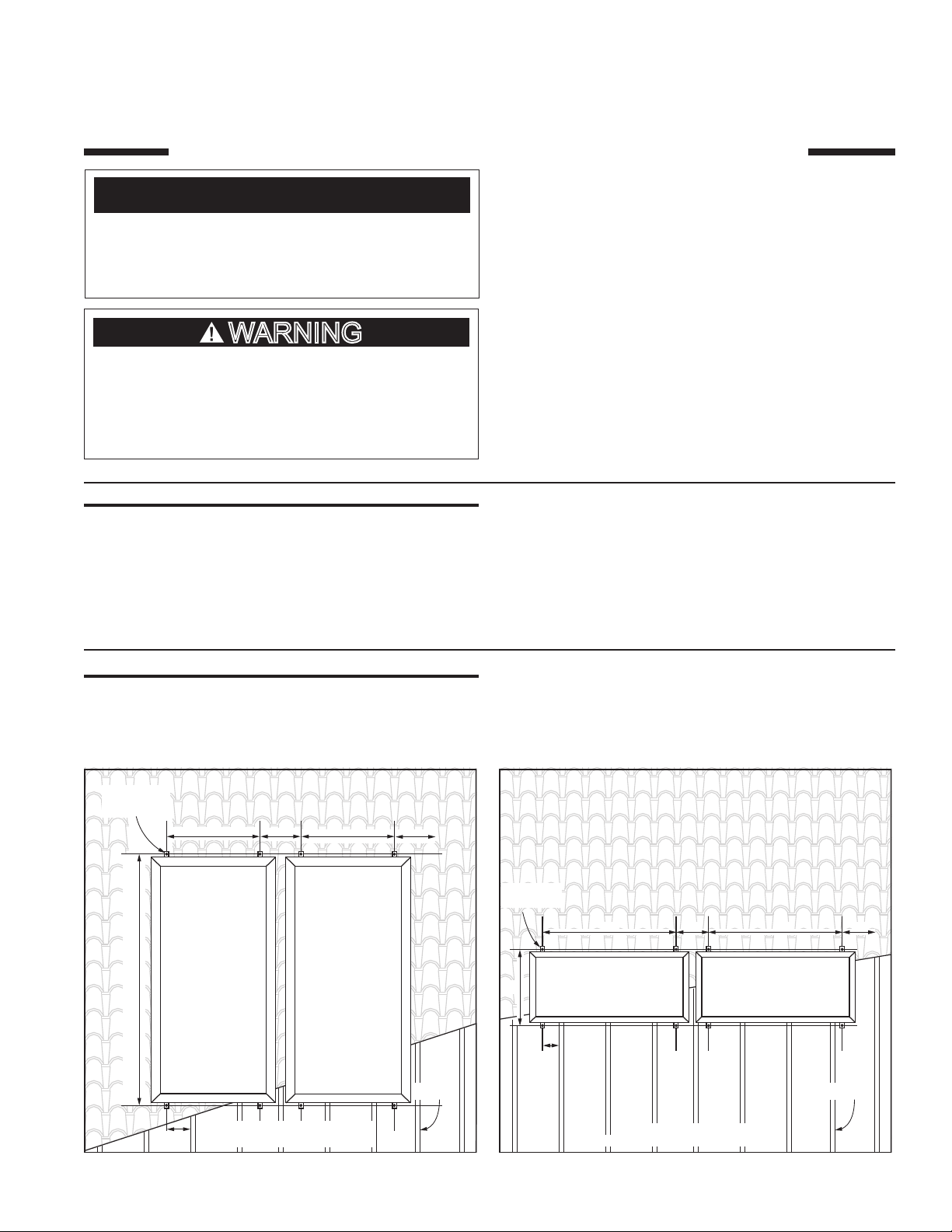
MOUNTING
POINTS
B” B”C”
A”
C”
RAFTER
MOUNTING
POINTS
A”
D”
B” B”C”
C”
RAFTER
D”
VERTICAL MOUNT
BASED ON 16” CENTER RAFTERS
Figure 1.
PRINTED 0311 319355-001
1
HORIZONTAL MOUNT
BASED ON 16” CENTER RAFTERS
Figure 2.
Page 2
NOTICE
* IF MOUNTING WITH AN OPTIONAL TILT MOUNT
KIT, FOR OPTIMAL COLLECTOR ANGLE REFER TO
ITS INSTRUCTION SHEET FOR THE APPLICABLE “A”
DIMENSION.
COLLECTOR A B C D
Vert. 3.5’ X 7’ 86* 32 14 7-1/4
Vert. 4’ X 8’ 97* 35 16 11-3/4
Vert. 4’ X 10’ 121* 35 16 11-3/4
Horiz. 3.5’ X 7’ 42.25* 62 28 13-1/2
Horiz. 4’ X 8’ 47* 72 28 12
Horiz. 4’ X 10’ 47* 94 30 9
Table 1.
1. Locate the mounting points for the mounting brackets
per Figure 1 for vertical mounting or Figure 2 for
horizontal mounting and Table 1. Layout the roof as
specified.
Figure 4.
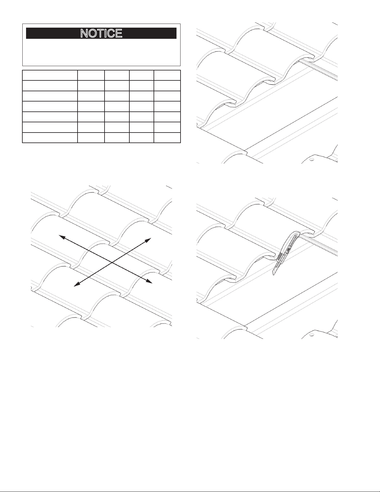
2. Determine which course of the roof you wish to
penetrate. It may be necessary to remove a few tiles to
locate the rafter locations. See Figures 3 & 4.
Figure 3.
Figure 5.
2
Page 3
Figure 6.
3. Determine the location of the flashing and cut a slit in the
roofing paper so the upslope edge of the flashing can
slide under the paper when installed. See Figures 5 & 6.
4. Once the flashing location has been determined, mark
the position of the center of the flashing bushing on the
roof paper. Remove the flashing.
5. Drill a 5/16” hole between the rafters at the center mark
of the flashing bushing.
using a 2” x 4” or similar lumber. Spanners must be
long enough to span at least two rafters. In the attic or
crawl space drill a 5/16” hole through each spanner and
insert the all-thread through it. Secure each spanner to
the rafters with decking or wood screws. See Figure 16.
9. Fabricate spacer blocks, one for each mounting bracket,
using a 2” x 4” or similar lumber the same width of the
rafter next to each all-thread. Place spacer blocks next
to the all-thread between the spanner and roof. Secure
each spacer block to the spanners with decking or
wood screws. Spacer blocks are necessary to avoid
deformation of the roof. See Figure 16.
10. With a stainless steel nut, lock washer and fender
washer secure the all-thread to each spanner. Tighten
down until the compression bracket washer is tightly
secured to the roof and flashing (approx. 97 inch
pounds). Be careful not to over tighten and dish out
the roof underneath the mounting bracket washer and
flashing. See Figure 16.
Figure 7.
6. Slide the flashing back under the roof paper and position
it so that the center of the flashing bushing is aligned
with the center of the drilled hole.
7. A piece of 12” length of stainless steel 5/16” all-thread
is then inserted through the hole in the roof and the
flashing bushing. Attach the compression bracket
washer and 5/16” x 3/8” SS reducer coupler to the 5/16”
SS –all thread as shown. The all-thread should extend
about 4” below the roof rafters. See Figures 7 & 16.
8. Fabricate spanners, one for each mounting bracket,
Figure 8.
11. Install an Ice & Water Shield (not included) around the
flashing to provide a water tight seal. See Figure 8.
3
Page 4

Figure 9.
12. Measure from the surrounding tiles to determine where
the 3/8” x 6” SS all-thread will penetrate the tile and
mark the tile accordingly.
13. Drill a 3/8” hole through the tile at the marked location.
See Figure 9.
Figure 10.
14. Replace the tile being certain that the drilled hole aligns
with the SS coupler. See Figure 10.
Figure 11.
15. Position the 3/8” SS all-thread through the hole in
the tile, thread it into the SS coupler and tighten. See
Figure 11.
Figure 12.
16. Thread a 3/8”-16 SS hex nut down the 3/8” SS all-thread
to just above the top surface of the tile. Do not tighten
the nut against the tile. See Figure 12.
17. Push one of the EPDM bonded washers down the 3/8”
all-thread until it rests against the top of the nut. Be
sure that the EPDM side is facing up. See Figure 12.
4
Page 5

Figure 13.
18. Clean the tile and cover the penetration with the
included 12” x 12” 3 Lb. lead flashing. Form the lead
flashing to match the contour of the tile. Measure and
drill a 3/8” hole in the lead flashing for the location of
the 3/8” all-thread. Be sure that there is a minimum of
3” of flashing all the way around the 3/8” all-thread and
tuck the up slope end of the flashing a minimum of 3”
up under the above tile. See Figure 13.
Figure 15.
21. Thread the support nut down the 3/8” all-thread to the
desired height. See Figure 15.
22. When installing the remainder of the support nuts be
sure all are at the same height as the others.
Figure 14.
19. Push another EPDM bonded washer down the threaded
rod until it rests against the top of the flashing being sure
that the EPDM side is facing down. Refer to Figure 14.
20. Thread another 3/8”-16 SS hex nut down the 3/8”
all-thread and tighten it against the washer. Refer to
Figure 14.
5
Page 6

ROOF
MEMBRANE
ROOF
TILES
MOUNTING
BRACKET
EPDM
WASHERS
LEAD
FLASHING
FLASHING
STAINLESS STEEL
ALL THREAD ROD, NUT,
LOCK WASHER &
FLAT WASHER
SUPPORT NUT
SS NUTS
REDUCING
COUPLING
CP COMPRESSION
WASHER
ROOF
RAFTER
SPACER
BLOCK
DECKING/WOOD
SCREWS
WOOD SPANNER
(2” x 4” or 2” x 6” LUMBER)
Figure 16.
23. Install the mounting brackets on top of the support nut
with the stainless steel flat washer, lock washer, & nut.
See Figure 16.
24. Install the mounting brackets on top of the support nut
with the stainless steel flat washer, lock washer, & nut.
See Figure 16.
25. Repeat steps 1 - 24 as needed for the remainder of the
mounting bracket locations.
PLYWOOD
SHEETING
ROOF
RAFTER
FENDER WASHER
LOCK WASHER & NUT
6
Page 7

ATTACHING COLLECTOR TO MOUNTING BRACKETS
Once all of the mounting brackets have been secured to
the roof the solar collector(s) can be installed. See Figure
17 for these instructions.
1. Insert the stainless steel channel nut w/spring inside
of the mounting bracket.
2. Fasten the solar collector mounting clip to the channel
nutwiththestainless steelbolt,lock-washer,andat
washer as shown. Do not tighten. Repeat step for the
other mounting bracket locations.
3. The solar collector can now be set on the mount-
ing brackets. To aid in handling the collectors on the
roof the mounting clips may be tightened to the lower
mounting brackets prior to raising the collectors. The
SOLAR COLLECTOR
FRAME
STAINLESS STEEL BOLT,
LOCK WASHER,
& FLAT WASHER
collector can then be set on the lower mounting brackets while the top clips are fastened over the lip on the
collector frame.
4. After the solar collector is in position, locate the upper
mounting clip so that its lip over-hangs the lip of the
solar collector frame as shown. Tighten the mounting
clip to the solar collector frame securely. Repeat for
the other upper mounting clips.
5. Once the upper mounting clips are secured, the bottom mounting clips can be loosened and retightened
over the collector lip as directed in step 4.
6. Repeat steps as needed for other solar collectors.
MOUNTING
CLIP
CHANNEL NUT
with SPRING
(One Piece Part)
MOUNTING
BRACKET
SUPPORT
NUT
Figure 17.
7
 Loading...