

Page 1
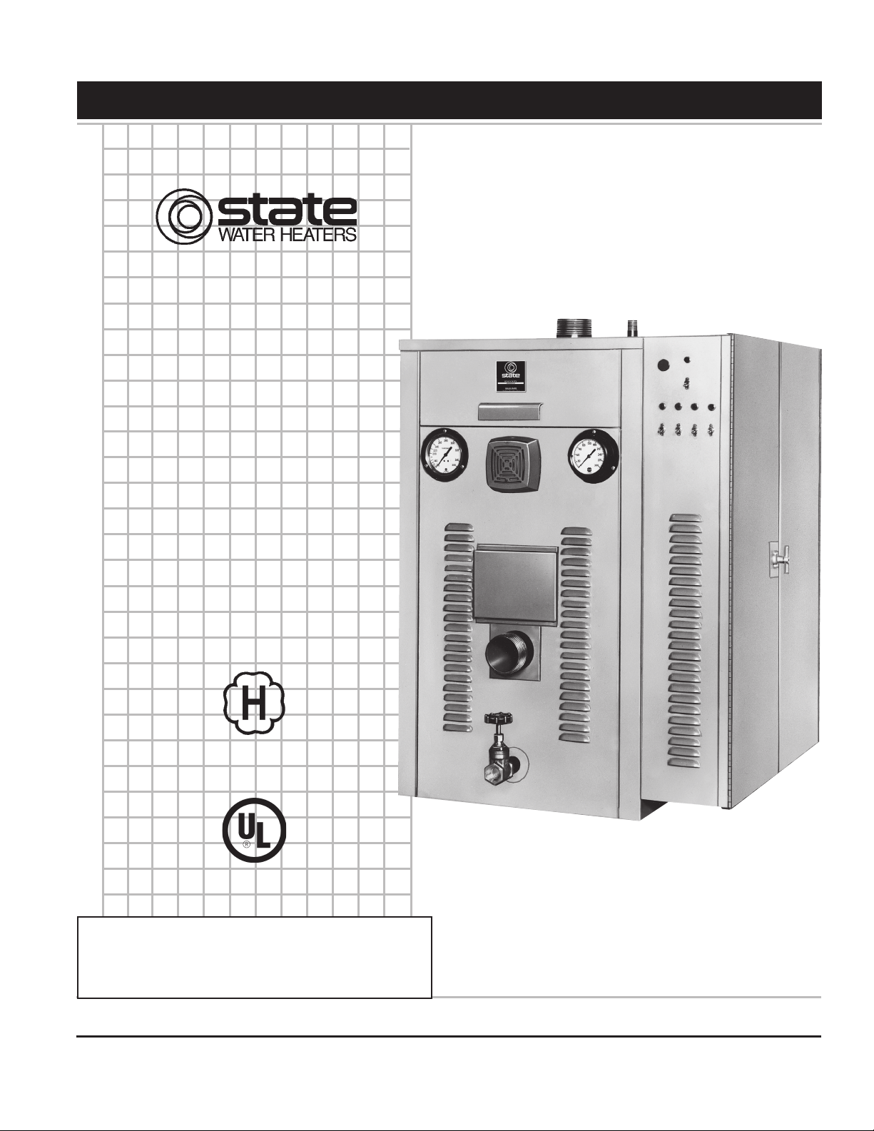
COMMERCIAL ELECTRIC BOILERS
A DIVISION OF A. O. SMITH CORPORATION
RENTON, WASHINGTON
www.statewaterheaters.com
Instruction Manual
MODELS SW 37-670
INSTALLATION - OPERATION - SERVICE -
MAINTENANCE - LIMITED WARRANTY
ASME
Thank you for buying this energy efficient boiler
from us. We appreciate your confidence in our
products.
PLACE THESE INSTRUCTIONS ADJACENT TO BOILER AND NOTIFY OWNER TO KEEP FOR FUTURE REFERENCE.
PRINTED 0110 316393-000
Page 2
SAFE INSTALLATION, USE AND SERVICE
Your safety and the safety of others is extremely important in the installation, use, and servicing of this boiler.
Many safety-related messages and instructions have been provided in this manual and on your own boiler to warn you and others of
a potential injury hazard. Read and obey all safety messages and instructions throughout this manual. It is very important that the
meaning of each safety message is understood by you and others who install, use, or service this boiler.
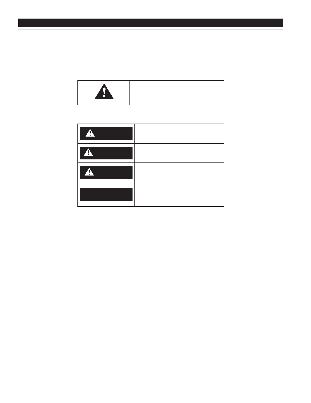
This is the safety alert symbol. It is used to alert
you to potential personal injury hazards. Obey all
safety messages that follow this symbol to avoid
possible injury or death.
DANGER indicates an imminently hazardous
DANGER
WARNING
CAUTION
situation which, if not avoided, will result in
death or injury.
WARNING indicates a potentially hazardous
situation which, if not avoided, could result in
death or injury.
CAUTION indicates a potentially hazardous
situation which, if not avoided, could result in
minor or moderate injury.
CAUTION used without the safety alert symbol
CAUTION
All safety messages will generally tell you about the type of hazard, what can happen if you do not follow the safety
message, and how to avoid the risk of injury.
The California Safe Drinking Water and Toxic Enforcement Act requires the Governor of California to publish a list of
substances known to the State of California to cause cancer, birth defects, or other reproductive harm, and requires
businesses to warn of potential exposure to such substances.
This product contains a chemical known to the State of California to cause cancer, birth defects, or other reproductive
harm. This appliance can cause low level exposure to some of the substances listed.
• QualiedInstallerorServiceAgency:
Installation and service of this boiler requires ability equivalent to that of a Qualied Agency (as dened by ANSI below) in the eld
involved. Installation skills such as plumbing and electrical supply are required in addition to electrical testing skills when performing
service.
indicates a potentially hazardous situation
which, if not avoided, could result in property
damage.
IMPORTANT DEFINITIONS
• ANSIZ223.12006Sec.3.3.83:
“Qualied Agency” - “Any individual, rm, corporation or company that either in person or through a representative is engaged in and is
responsible for (a) the installation, testing or replacement of gas piping or (b) the connection, installation, testing, repair or servicing of
appliances and equipment; that is experienced in such work; that is familiar with all precautions required; and that has complied with all
the requirements of the authority having jurisdiction.”
2
Page 3
GENERAL SAFETY INFORMATION
PRECAUTIONS
DO NOT USE THIS APPLIANCE IF ANY PART HAS BEEN UNDER
WATER. Immediately call a qualied service technician to inspect
the appliance and to replace any part of the control system which
has been under water.
If the unit is exposed to the following, do not operate boiler until all
corrective steps have been made by a qualied service agency.
1. External re.
2. Damage.
3. Firing without water.
GROUNDING INSTRUCTIONS
This boiler must be grounded in accordance with the National Electrical
Code and/or local codes. These must be followed in all cases. Failure
to ground this boiler properly may also cause erratic control system
operation on ELECTRONIC CONTROL models.
This boiler must be connected to a grounded metal, permanent wiring
system, or an equipment grounding conductor must be run with
the circuit conductors and connected to the equipment grounding
terminal or lead on the boiler.
When servicing this unit, verify the power to the unit is turned off prior to opening the control cabinet door.
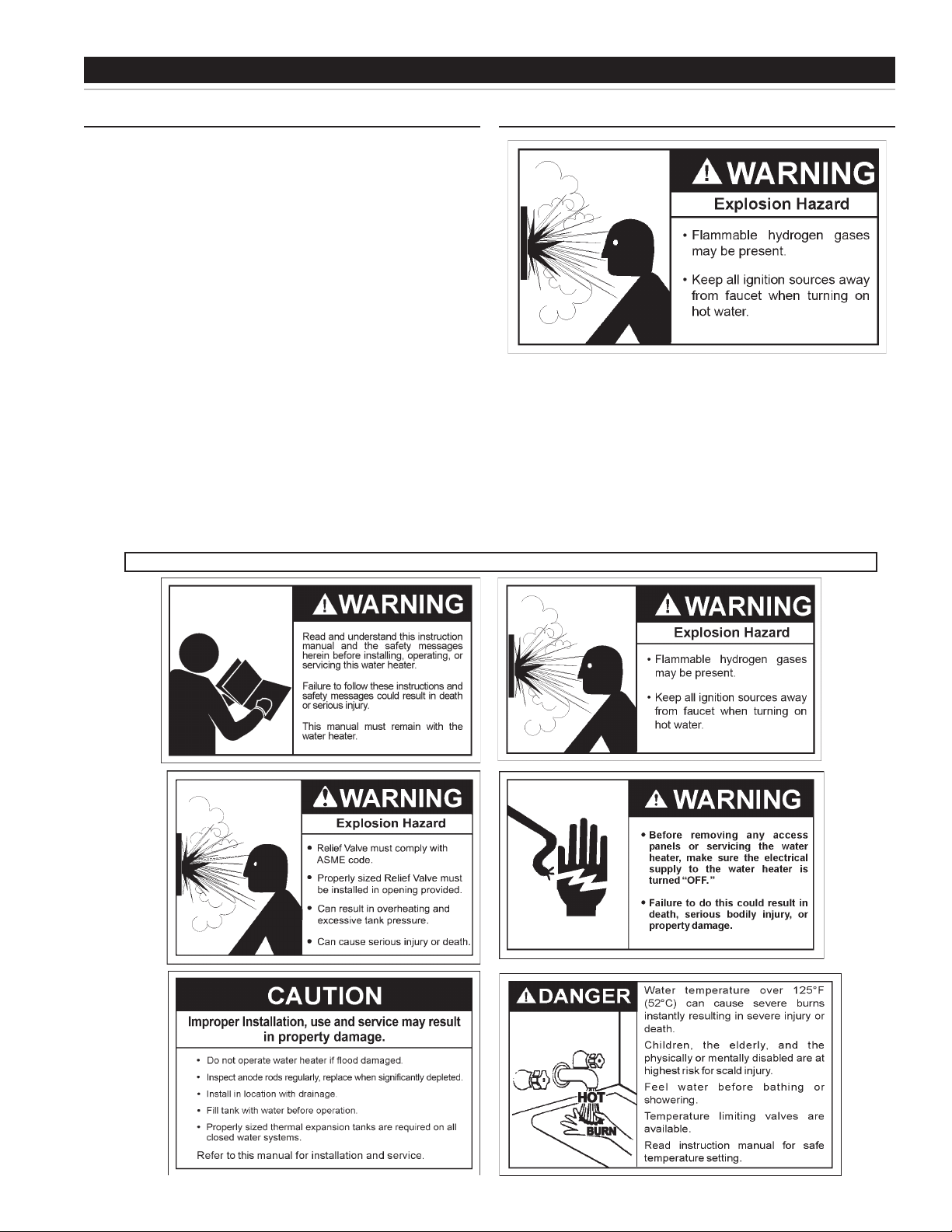
HYDROGEN GAS (FLAMMABLE)
Hydrogen gas can be produced in a hot water system served by this boiler
that has not been used for a long period of time (generally two weeks or
more). Hydrogen gas is extremely ammable. To reduce the risk of injury
under these conditions, it is recommended that the hot water faucet be
opened for several minutes at the kitchen sink before using any electrical
appliance connected to the hot water system. If hydrogen is present there
will probably be an unusual sound such as air escaping through the pipe
as the water begins to ow. THERE SHOULD BE NO SMOKING OR
OPEN FLAME NEAR THE FAUCET AT THE TIME IT IS OPEN.
3
Page 4

TABLE OF CONTENTS
SAFE INSTALLATION, USE AND SERVICE...........................................................2
GENERAL SAFETY INFORMATION .......................................................................3
Precautions ....................................................................................................3
Hydrogen Gas (Flammable) ...........................................................................3
TABLE OF CONTENTS ...........................................................................................4
INTRODUCTION .....................................................................................................4
Preparing for the Installation ..........................................................................4
DIMENSIONS AND CAPACITIES DATA .................................................................5
FEATURES AND COMPONENTS ..........................................................................8
APPROVALS ...........................................................................................................9
MODEL AND RATING .............................................................................................9
LOCATING THE NEW BOILER ...............................................................................9
Facts to Consider About the Location ............................................................9
INSTALLATION .....................................................................................................10
Required Ability ............................................................................................10
General ........................................................................................................10
Pressure Relief Valve ...................................................................................10
Water Line Connections ...............................................................................10
Closed Water Systems ................................................................................. 11
Thermal Expansion ......................................................................................11
ELECTRICAL DATA ...............................................................................................12
General ........................................................................................................12
Branch Circuit ...............................................................................................12
Calculating Amperage/Overcurrent Protection .............................................12
Boiler Circuits ...............................................................................................12
Control Circuits .............................................................................................12
WIRING DIAGRAMS .............................................................................................13
OPERATION ..........................................................................................................15
Important ......................................................................................................15
General ........................................................................................................15
High Temperature Limit ................................................................................15
Filling the Boiler ............................................................................................15
Initial Start Up ...............................................................................................15
Temperature Regulation ...............................................................................15
Temperature Controls ...................................................................................16
Draining ........................................................................................................16
MAINTENANCE ....................................................................................................17
Schedule ......................................................................................................17
System Cleaning ..........................................................................................17
Flushing ........................................................................................................17
Sediment Removal .......................................................................................17
Lime Scale Removal ....................................................................................17
TROUBLESHOOTING CHECKLIST .....................................................................18
Not Enough or No Hot Water .......................................................................18
Water is Too Hot ...........................................................................................18
Boiler Makes Strange Sounds ......................................................................18
Leakage Checkpoints ...................................................................................18
WARRANTY ..........................................................................................................19
INTRODUCTION
Thank You for purchasing this boiler. Properly installed and
maintained, it should give you years of trouble free service.
Abbreviations Found In This Instruction Manual:
• ANSI - American National Standards Institute
• ASME - American Society of Mechanical Engineers
• GAMA - Gas Appliance Manufacturer’s Association
• NEC - National Electrical Code
• NFPA - National Fire Protection Association
• UL - Underwriters Laboratory
PREPARING FOR THE INSTALLATION
1. Read the “General Safety” section of this manual rst and
then the entire manual carefully. If you don’t follow the safety
rules, the boiler may not operate safely. It could cause DEATH,
SERIOUS BODILY INJURY AND/OR PROPERTY DAMAGE.
This manual contains instructions for the installation, operation,
and maintenance of the electric boiler. It also contains warnings
throughout the manual that you must read and be aware of.
All warnings and all instructions are essential to the proper
operation of the boiler and your safety. READ THE ENTIRE
MANUAL BEFORE ATTEMPTING TO INSTALL OR OPERATE
THE BOILER.
Detailed installation diagrams are in this manual. These
diagrams will serve to provide the installer with a reference
for the materials and method of piping suggested. IT
IS NECESSARY THAT ALL WATER PIPING AND THE
ELECTRICAL WIRING BE INSTALLED AND CONNECTED
AS SHOWN IN THE DIAGRAMS.
Particular attention should be given to the installation of
thermometers at the locations indicated in the diagrams as
these are necessary for checking the operation of the heater.
fuses always use the correct size for the circuit. See page 12
through 14.
The principal components of the heater are identied on page 8.
The model and rating plate on page 9 interprets certain markings
into useful information. Both of these references should be used
to identify the heater, its components and optional equipment.
2. The installation must conform with these instructions and the
local code authority having jurisdiction and the requirements
of the power company. In the absence of code requirements,
follow NFPA-70 (current edition). The National Electrical Code
may be ordered from: National Fire Protection Association, 1
Batterymarch Park, Quincy, MA 02269.
3. If after reading this manual you have any questions or do not
understand any portion of the instructions, call the toll free
number on the back cover for further assistance.
A sample rating plate and barcode tag are shown on page 9 of
this manual. In order to expedite your request, please have the
serial number and item ID from the barcode tag available for the
technician.
4. Carefully plan your intended placement of the boiler. Examine
the location to ensure the boiler complies with the “Locating the
New Boiler” section in this manual.
Installation and service of this boiler requires ability equivalent
to that of a licensed tradesman or qualied agency (page 2) in
the eld involved. Plumbing and electrical work are required.
5. For installation in California this boiler must be braced or
anchored to avoid falling or moving during an earthquake. See
instructions for correct installation procedures. Instructions may
be obtained from California Ofce of the State Architect, 1102 Q
Street, Suite 5100, Sacramento, CA 95811.
Be sure to turn off power when working on or near the electrical
system of the heater. Never touch electrical components
with wet hands or when standing in water. When replacing
6. Massachusetts Code requires this boiler to be installed in
accordance with Massachusetts 248-CMR 2.00: State Plumbing
Code and 248-CMR 5.00.
4
Page 5
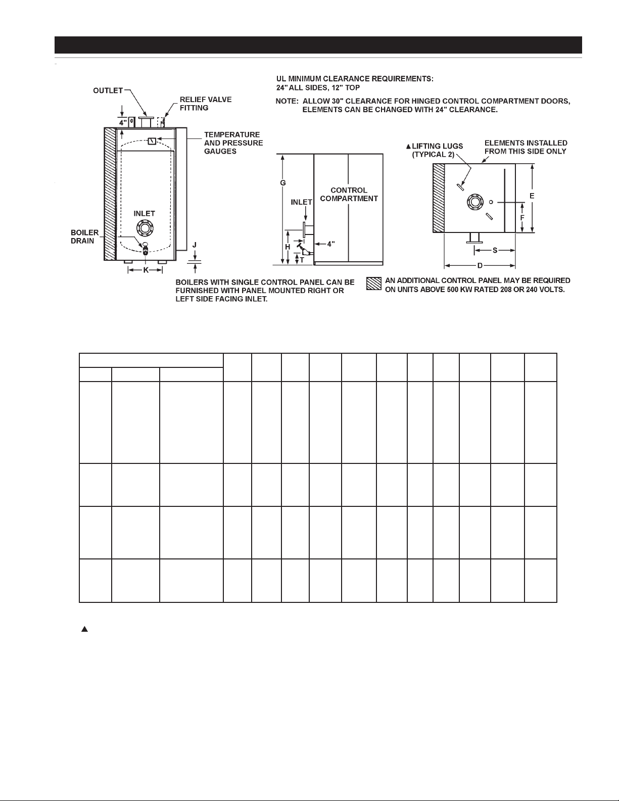
DIMENSION DATA
SIZES AND DATA NW37 THRU NW150
Model Number
Prex Gal. Cap. Std. KW Input
SW
SW
SW
SW
SW
SW
SW
SW
SW
SW
SW
SW
SW
SW
SW
SW
SW
SW
SW
SW
SW
* All ttings under 4” will be threaded type. All ttings 4” and larger will be anged. 3” ttings extend 4” beyond jacket.
** Where overall height is a problem a larger diameter vessel with a reduced height may be furnished.
Lifting lugs and channel skid base on 96 gallon and larger units.
37
37
37
37
37
37
37
37
60
60
60
60
96
96
96
96
96
150
150
150
150
45K
60K
75K
90K
105K
120K
150K
180K
210K
240K
270K
300K
330K
390K
420K
450K
480K
540K
600K
660K
720K
D E F G** H J K S T
32
30
12
42
32
32
32
32
32
32
32
32
32
32
32
36
36
36
36
36
46
46
46
46
30
30
30
30
30
30
30
30
30
30
30
38
38
38
38
38
44
44
44
44
12
12
12
12
12
12
12
12
12
12
12
16
16
16
16
16
19
19
19
19
42
42
42
42
42
42
42
57
57
57
57
69 1/2
69 1/2
69 1/2
69 1/2
69 1/2
69 1/2
69 1/2
69 1/2
69 1/2
12 1/2
12 1/2
12 1/2
12 1/2
12 1/2
12 1/2
12 1/2
12 1/2
12 1/2
12 1/2
12 1/2
12 1/2
17
17
17
17
17
20
20
20
20
-
-
-
-
-
-
-
-
-
-
-
-
1 1/2
1 1/2
1 1/2
1 1/2
1 1/2
2
2
2
2
17
17
17
17
17
20
20
20
20
-
20
-
20
-
20
-
20
-
20
-
20
-
20
-
20
-
20
-
20
-
20
-
20
22
22
22
22
22
27
27
27
27
Inlet* &
Outlet*
4
4
4
4
4
4
4
4
4
4
4
4
5
5
5
5
5
5 1/2
5 1/2
5 1/2
5 1/2
Boiler
Drain
3
3
2
3
3
3
3
3
3
3
3
3
4
4
4
4
4
5
5
5
5
1
1
1
1
1
1
1
1
1
1
1
1
1 1/4
1 1/4
1 1/4
1 1/4
1 1/4
1 1/2
1 1/2
1 1/2
1 1/2
5
Page 6
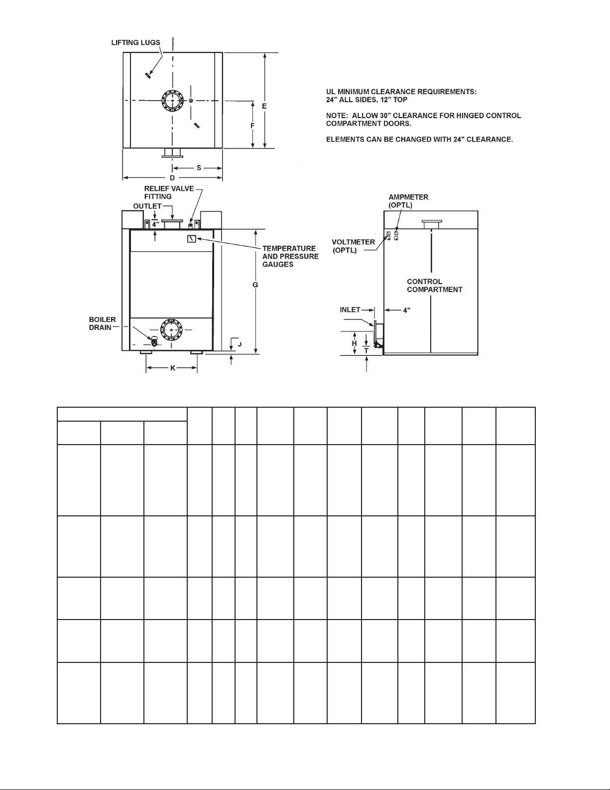
SIZES AND DATA NW220 THRU 670
Model Number
Prex Gal. Cap.
SW
SW
SW
SW
SW
SW
SW
SW
SW
SW
SW
SW
SW
SW
SW
SW
SW
SW
SW
SW
SW
SW
SW
SW
SW
SW
SW
NOTE: For boilers 3400KW to 6000KW, consult factory.
* All ttings under 4” will be threaded type. All ttings 4” and larger will be anged.
** Where overall height is a problem a larger diameter vessel with a reduced height may be furnished.
220
220
220
220
220
220
220
334
334
334
334
334
334
400
400
400
400
500
500
500
500
670
670
670
670
670
670
Std. KW
Input
780K
840K
900K
960K
1020K
1080K
1140K
1200K
1260K
1380K
1500K
1620K
1740K
1800K
1860K
1980K
2100K
2200K
2340K
2460K
2580K
2700K
2820K
2940K
3060K
3180K
3300K
D E F G** H J K S T
60
50
25
60
60
60
60
60
60
60
60
60
60
60
60
66
66
66
66
72
72
72
72
78
78
78
78
78
78
50
50
50
50
50
50
50
50
50
50
50
50
56
56
56
56
62
62
62
62
68
68
68
68
68
68
25
25
25
25
25
25
25
25
25
25
25
25
28
28
28
28
31
31
31
31
34
34
34
34
34
34
71
71
71
71
71
71
71
99
99
99
99
99
99
90 1/2
90 1/2
90 1/2
90 1/2
90 1/2
90 1/2
90 1/2
90 1/2
96 1/2
96 1/2
96 1/2
96 1/2
96 1/2
96 1/2
21
21
21
21
21
21
21
25
25
25
25
25
25
25 1/2
25 1/2
25 1/2
25 1/2
26 1/2
26 1/2
26 1/2
26 1/2
30 1/2
30 1/2
30 1/2
30 1/2
30 1/2
30 1/2
2
2
2
2
2
2
2
2
2
2
2
2
2
2 1/2
2 1/2
2 1/2
2 1/2
2 1/2
2 1/2
2 1/2
2 1/2
2 1/2
2 1/2
2 1/2
2 1/2
2 1/2
2 1/2
25 1/2
25 1/2
25 1/2
25 1/2
25 1/2
25 1/2
25 1/2
25 1/2
25 1/2
25 1/2
25 1/2
25 1/2
25 1/2
30
30
30
30
34
34
34
34
38
38
38
38
38
38
30
30
30
30
30
30
30
30
30
30
30
30
30
33
33
33
33
36
36
36
36
39
39
39
39
39
39
5 1/2
5 1/2
5 1/2
5 1/2
5 1/2
5 1/2
5 1/2
7 1/4
7 1/4
7 1/4
7 1/4
7 1/4
7 1/4
7 3/4
7 3/4
7 3/4
7 3/4
7 3/4
7 3/4
7 3/4
7 3/4
7 3/4
7 3/4
7 3/4
7 3/4
7 3/4
7 3/4
Inlet* &
Outlet*
5
5
5
5
5
5
5
6
6
6
6
6
6
8
8
8
8
8
8
8
8
8
8
8
8
8
8
Boiler
Drain
1 1/2
1 1/2
1 1/2
1 1/2
1 1/2
1 1/2
1 1/2
2
2
2
2
2
2
2
2
2
2
2
2
2
2
2
2
2
2
2
2
6
Page 7

DIMENSION DATA (cont’d)
BOILER SPECIFICATIONS (STANDARD)
Model Number
Prex Gal. Cap.
SW
SW
SW
SW
SW
SW
SW
SW
SW
SW
SW
SW
SW
SW
SW
SW
SW
SW
SW
SW
SW
SW
SW
SW
SW
SW
SW
SW
SW
SW
SW
SW
SW
SW
SW
SW
SW
SW
SW
SW
SW
SW
SW
SW
SW
SW
NOTE: For boilers 3000KW to 6000KW consult factory.
*Consult factory for optional number of steps and Kw per step.
37
37
37
37
37
37
37
37
60
60
60
60
96
96
96
96
96
96
150
150
150
150
220
220
220
220
220
220
220
334
334
334
334
334
334
400
400
400
400
500
500
500
500
670
670
670
Std. KW
Input
45K
60K
75K
90K
105K
120K
150K
180K
210K
240K
270K
300K
330K
360K
390K
420K
450K
480K
540K
600K
660K
720K
780K
840K
900K
960K
1020K
1080K
1140K
1200K
1260K
1380K
1500K
1620K
1740K
1800K
1860K
1980K
2100K
2220K
2340K
2460K
2580K
2700K
2820K
2940K
BTU
Output
153,585
204,720
255,975
307,170
358,365
409,560
511,950
614,340
716,730
819,120
921,510
1,023,900
1,126,290
1,228,680
1,331,070
1,433,460
1,535,850
1,638,240
1,843,020
2,047,800
2,252,580
2,457,360
2,662,140
2,866,920
3,071,700
3,276,480
3,481,260
3,636,040
3,890,820
4,095,600
4,300,380
4,709,940
5,119,500
5,529,060
5,938,630
6,143,400
6,348,180
6,757,740
7,167,300
7,576,860
7,986,420
8,395,980
8,805,540
9,315,100
9,624,660
10,034,220
Gal./Hr.
100°F
Rise
180
240
300
369
430
492
615
738
861
984
1107
1230
1353
1476
1599
1722
1845
1968
2214
2460
2706
2952
3198
3444
3690
3936
4182
4428
4674
4920
5166
5658
6150
6642
7134
7380
7626
8118
8610
9102
9594
10080
10578
11070
11562
12054
Number
of
Elements
3
4
5
6
7
8
10
12
14
16
18
20
22
24
26
28
30
32
36
40
44
48
52
56
60
64
68
72
76
80
84
92
100
108
116
120
124
132
140
148
156
164
172
180
188
196
Number
of Steps
*
1
1
1
3
4
4
5
6
7
8
9
10
10
10
10
10
10
10
10
10
10
10
10
10
10
10
10
10
10
10
10
10
10
16
17
17
17
18
19
15
20
20
20
20
20
20
Standard Number and
KW of Steps
*
1@45
1@60
1@75
3@30
3@30+1@15
4@30
5@30
6@30
7@30
8@30
9@30
10@30
1@60+9@30
2@60+8@30
3@60+7@30
4@60+6@30
5@60+5@30
6@60+4@30
8@60+2@30
10@60
8@60+2@90
4@90+6@60
6@90+4@60
9@90+1@30
10@90
8@90+2@120
6@90+4@120
4@90+6@120
2@90+8@120
10@120
8@120+2@150
4@120+6@150
10@150
10@90+6@120
10@90+7@120
8@90+9@120
6@90+11@120
6@90+12@120
6@90+13@120
1@120+14@150
18@120+2@90
18@120+2@150
14@120+6@150
10@120+10@150
6@120+14@150
2@120+18@150
Amperage 3 Phase
208V 240V 480V 575V
128
171
213
250
292
334
417
500
584
668
751
834
917
1001
1084
1168
1251
1334
1501
1668
108
144
180
217
253
289
361
433
505
577
650
722
794
866
938
1010
1083
1155
1299
1443
55
73
90
108
126
144
180
216
252
288
324
360
396
432
468
504
540
576
648
720
792
864
936
1008
1080
1152
1224
1296
1368
1440
1512
1656
1800
1944
2068
2160
2232
2376
2520
2664
2808
2952
3096
3240
3384
3528
45
60
75
90
105
121
151
181
211
241
271
301
331
362
392
422
452
487
542
602
663
723
783
843
904
964
1024
1084
1145
1205
1265
1386
1506
1627
1747
1807
1868
1988
2109
2229
2350
2470
2590
2711
2832
2952
7
Page 8
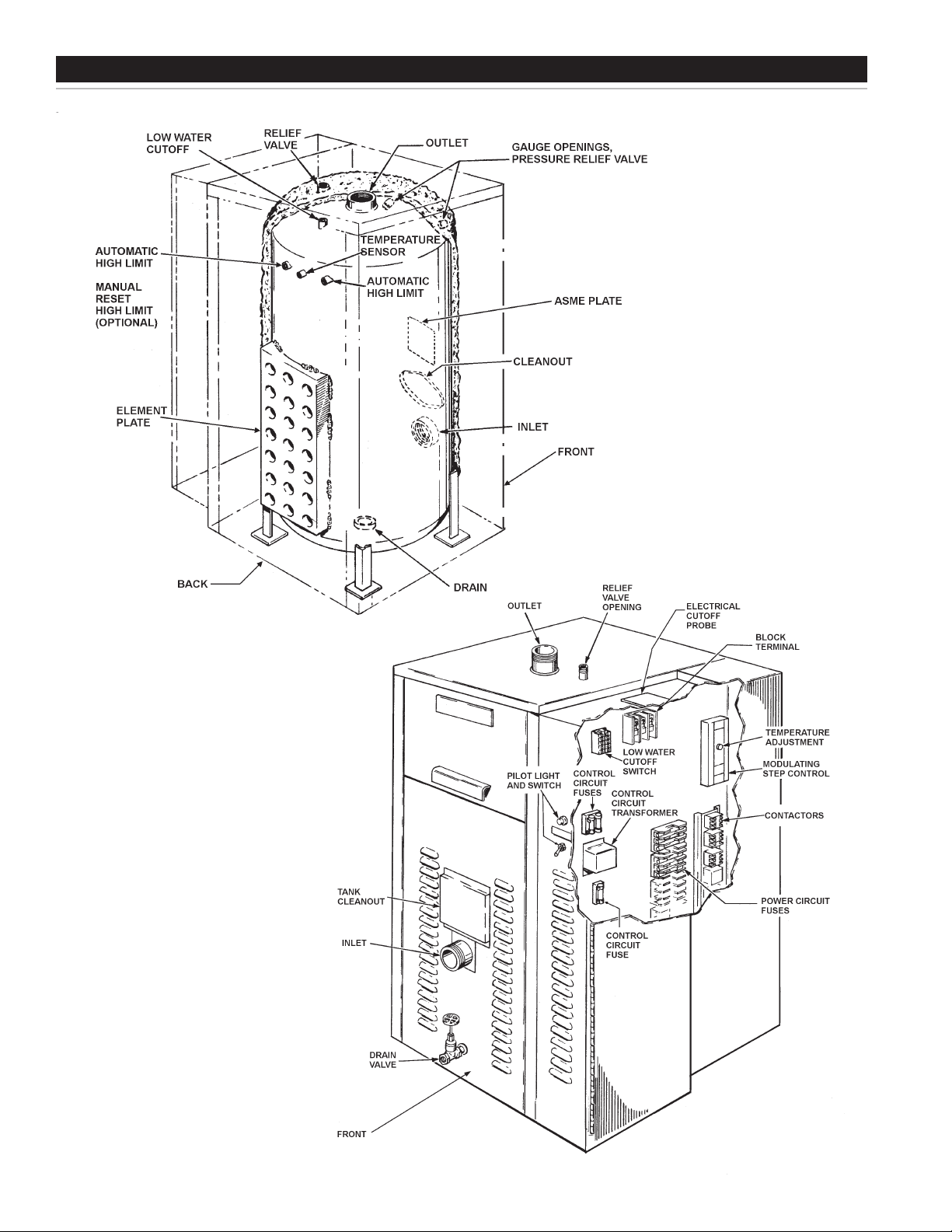
FEATURES AND COMPONENTS
ACTUAL CONFIGURATION MAY VARY.
8
Page 9

APPROVALS
ASME
MODEL AND RATING
LOCATING THE BOILER
FACTS TO CONSIDER ABOUT THE LOCATION
Carefully choose a location for the boiler. The placement is a very
important consideration for the safety of the occupants in the building
and for the most economical use of the appliance.
Whether replacing an old boiler or putting the boiler in a new location,
the following critical points must be observed. The boiler must be
located:
1. On a level surface. Shim the channel type skid base as
necessary if levelling is required.
2. Near a oor drain. The boiler should be located in an area
where leakage of the tank or connections will not result in
damage to the area adjacent to the boiler or to lower oors of
the structure.
3. The discharge opening of the temperature and pressure relief
valve should always be piped to an open drain.
4. Close to the point of major hot water usage and the power supply.
Hot water piping and branch circuit wiring should be as short as possible.
Insulate hot and cold water piping where heat loss and condensation
may be a problem.
Boiler construction permits installation, maintenance, and service
work to be performed through panels located in multiple sides of the
boiler.
Suggested clearances from adjacent surfaces are 12 inches on top,
30 inches in front for access to the unit.
The boiler may be installed in a conned space if adequate ventilation
is provided.
The temperature of the space in which the boiler is installed must not
go below 32°F or above 122°F.
9
Page 10
INSTALLATION
REQUIRED ABILITY
Installation and service of this boiler requires ability equivalent to that
of a qualied agency (page 2) in the eld involved. Plumbing and
electrical work is required.
GENERAL
The installation must conform with these instructions and the
local code authority having jurisdiction and the requirements of
the power company. In the absence of code requirements, follow
NFPA-70 (current edition). In the absence of local codes, the
installation must comply with the latest editions of the National
Electrical Code, NFPA 70 or the Canadian Electrical Code CSA
C22.1. The National Electrical Code may be ordered from:
National Fire Protection Association, 1 Batterymarch Park, Quincy,
MA 02269. The Canadian Electrical Code is available from the
Canadian Standards Association, 8501 East Pleasant Valley Road,
Cleveland, OH 44131.
Do NOT test electrical system before boiler is lled with water,
follow the START UP procedure in the OPERATION section of this
manual.
The principal components of the boiler are identied in the Features
and Components illustration on page 8.
A discharge pipe from the relief valve should terminate at an
adequate oor drain. Do not thread, plug, or cap the end of the
drain line.
Boilers are usually placed in a series with the heating system on
the outlet side of the circulating pump. The boiler piping should
include inlet and outlet water valves to permit maintenance and
service work to be performed without disturbing the rest of the
system.
Detailed system installation drawings are normally provided by the
equipment purchaser or system designer.
PRESSURE RELIEF VALVE
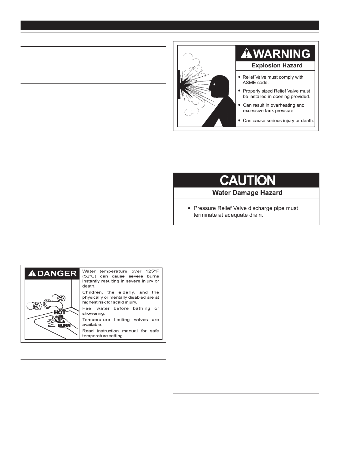
An ASME rated pressure relief valve is furnished with the boiler. A
tting for the relief valve is provided in the top of the boiler. Never
operate the heating elements without being certain the boiler is lled
with water and a properly sized pressure relief valve is installed in
the relief valve opening provided.
The pressure rating of the relief valve should be equal to or less
than the rated pressure capacity of any component in the system
including the boiler. Should the valve need to be replaced, call the
toll free phone number listed on the back of this manual for further
technical assistance.
The Discharge Pipe:
• Shall not be smaller in size than the outlet pipe size of the valve,
or have any reducing couplings or other restrictions.
• Shall not be plugged or blocked.
• Shall not be exposed to freezing temperatures.
• Shall be of material listed for hot water distribution.
• Shall be installed so as to allow complete drainage of both the
relief valve and the discharge pipe.
• Must terminate a maximum of six inches above a oor drain or
external to the building. In cold climates, it is recommended that
the discharge pipe be terminated at an adequate drain inside the
building.
• Shall not have any valve or other obstruction between the relief
valve and the drain.
Once the boiler is installed and lled with water and the system is
pressurized, manually test the operation of the pressure relief valve.
See the maintenance section of this manual forinstructions.
WATER LINE CONNECTIONS
The boiler may be installed by itself, or with a separate storage tank,
on both single and two-temperature systems. When used with a
separate storage tank, the circulation may be either by gravity or
by means of a circulating pump. When a circulating pump is used
it is important to note that the ow rate should be slow so that there
will be a minimum of turbulence inside the heater.
10
Page 11

CLOSED WATER SYSTEMS
Water supply systems may, because of code requirements or such
conditions as high line pressure, among others, have installed
devices such as pressure reducing valves, check valves, and
back flow preventers. Devices such as these cause the water
system to be a closed system.
THERMAL EXPANSION
As water is heated, it expands (thermal expansion). In a closed
system the volume of water will grow when it is heated. As the
volume of water grows there will be a corresponding increase in
water pressure due to thermal expansion. Thermal expansion
can cause premature tank failure (leakage). This type of failure
is not covered under the limited warranty. Thermal expansion
can also cause intermittent pressure relief valve operation: water
discharged from the valve due to excessive pressure build up.
This condition is not covered under the limited warranty. The
pressure relief valve is not intended for the constant relief of
thermal expansion.
A properly sized thermal expansion tank should be install ed
on all closed systems to control the harmful effects of thermal
expansion. Contact a local plumbing service agency to have a
thermal expansion tank installed.
11
Page 12

ELECTRICAL DATA
GENERAL
Check the boiler model and rating plate information against the
characteristics of the branch circuit electrical supply. Do not connect
the boiler to an improper source of electricity.
Voltage applied to the boiler should not vary more than + 5% to -10%
of the model and rating plate marking for satisfactory operation.
Do not energize the branch circuit for any reason before the boiler is
lled with water. Doing so may cause the heating elements to burn
out. Such damage is not covered under the terms of the warranty.
The branch circuit is connected to the block through an opening
provided on top of the boiler.
The boiler should be connected to a separate, grounded, branch
circuit with overcurrent protection and disconnect switch. These are
part of the electrical supply system not components of the boiler,
as such they are obtained locally. The boiler should be grounded in
accordance with national and local codes.
BRANCH CIRCUIT
The branch circuit wire size should be established through reference
to the National Electrical Code or other locally approved source in
conjunction with boiler amperage rating. Branch circuit wiring which
connects to the boiler terminal block should be temperature rated
at 75°C. For convenience, portions of the wire size tables from the
Code are reproduced here. It is suggested the electrician size the
branch circuit at 125 percent of the boiler rating and further increase
wire size as necessary to compensate for voltage drop in long runs.
Branch circuit voltage drop should not exceed 3% at the boiler.
CALCULATING AMPERAGE/
OVERCURRENT PROTECTION
The boiler is factory wired for connection to three wire single-phase
or three and four wire three-phase branch circuits. In addition, a
ground conductor may be required.
A diagram of the wiring “as built” is furnished with the boiler for the
electrician’s use. An amperage table is on pages 7 & 12 of this manual.
The boiler model and rating plate provides full load amperage data.
Typical or Standard wiring diagrams are provided on pages 13 & 14
of this manual.
The rating of the overcurrent protection should be computed on the
basis of 125 percent of the total connected load amperage. Where the
standard ratings and settings do not correspond with this computation,
the next higher standard rating or setting should be selected.
BOILER CIRCUITS
The boiler’s electrical components are pictured and identied on
page 8. The model and rating plate illustration on page 9 identies the
electrical characteristics. Basically, there are two electrical circuits:
• The control circuit, where the temperature control directly or
indirectly operates the contactor coils.
• The power circuit, which is operated by the control circuit, carries
the electrical load of the heating elements.
The following describes the circuits and includes typical wiring diagrams.
All circuits are designed for 60 or 50 Hertz alternating current.
Refer to ELECTRICAL CONFIGURATION TABLE, below, and wiring
diagram provided with your boiler before completing connections to
electrical supply.
NOTE: Wiring diagrams in this manual are typical examples. The
specic wiring diagram “as built” for your boiler is typically attached to
the “inner side” of the control panel.
CONTROL CIRCUIT
All control circuits are operated on single-phase 120V. A transformer
is used in the control circuit.
Control circuit wiring is 14 Awg, THHN or THWN type, rated 600
volts, 105°C.
Seperate instructional literature is provided with the boiler for step control.
Portion of Table 310-16
Allowable Ampacities of Insulated
Copper Conductors
Not more than three conductors in
raceway or cable or direct burial
(based on ambient temperature of
Size
AWG
MCM
18
16
14
12
10
8
6
4
3
2
1
1/0
2/0
3/0
4/0
250
300
350
400
500
600
700
750
800
900
1000
1250
1500
1750
2000
30°C, 86°F.)
Temperature
Rating of
Conductor. See
Table 310-13 in
Code Size
75°C (167°F)
Types RH,
RHW, RUH (14-
2), THW, THWN,
XHHW, USE
- - - - -
- - - - -
100
115
130
150
175
200
230
255
285
310
335
380
420
460
475
490
520
545
590
625
650
665
12
15
20
30
45
65
85
Portion of Table 310-16
Allowable Ampacities of Insulated
Aluminum and Copper-Clad
Aluminum Conductors
Not more than three conductors in
raceway or cable or direct burial
(based on ambient temperature of
These capacites relate only to conductors
described in Table 310-13 in Code.
For ambient temperatures over 30°C, see
Correction Factors, Note 13 in Code
AWG
MCM
12
10
8
6
4
3
2
1
1/0
2/0
3/0
4/0
250
300
350
400
500
600
700
750
800
900
1000
1250
1500
1750
2000
30°C, 86°F.)
Temperature
Rating of
Conductor. See
Table 310-13 in
Code
75°C (167°F)
Types RH,
RHW, RUH (12-
2), THW, THWN,
XHHW, USE
15
25
40
50
65
75
90
100
120
135
155
180
205
230
250
270
310
340
375
385
395
425
445
485
520
545
560
Page 13
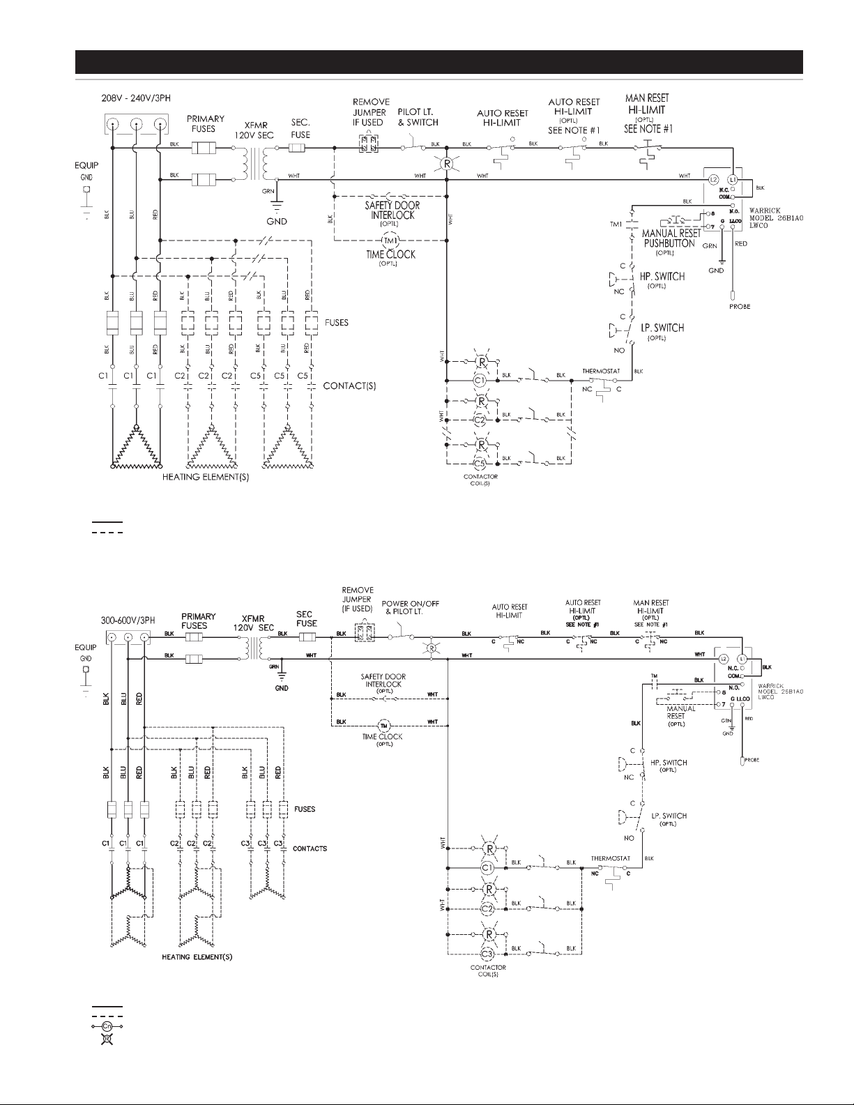
WIRING DIAGRAMSWIRING DIAGRAMS
NOTE(S):
1. IF A MANUAL RESET HLMT IS USED, THE SECOND AUTO RESET HLMT
SWITCH IS NOT USED.
STD. WIRING
OPTIONAL OR FIELD WIRING AS REQ’D
THREE PHASE DELTA WITH THERMOSTAT
DIAGRAM 1.
NOTE(S):
1. IF A MANUAL RESET HLMT IS USED, THE SECOND AUTO RESET HLMT
SWITCH IS NOT USED.
STD. WIRING
OPTIONAL OR FIELD WIRING AS REQ’D
CONTACTOR COIL
INDICATION LIGHT
THREE PHASE WYE WITH THERMOSTAT
DIAGRAM 2.
13
Page 14
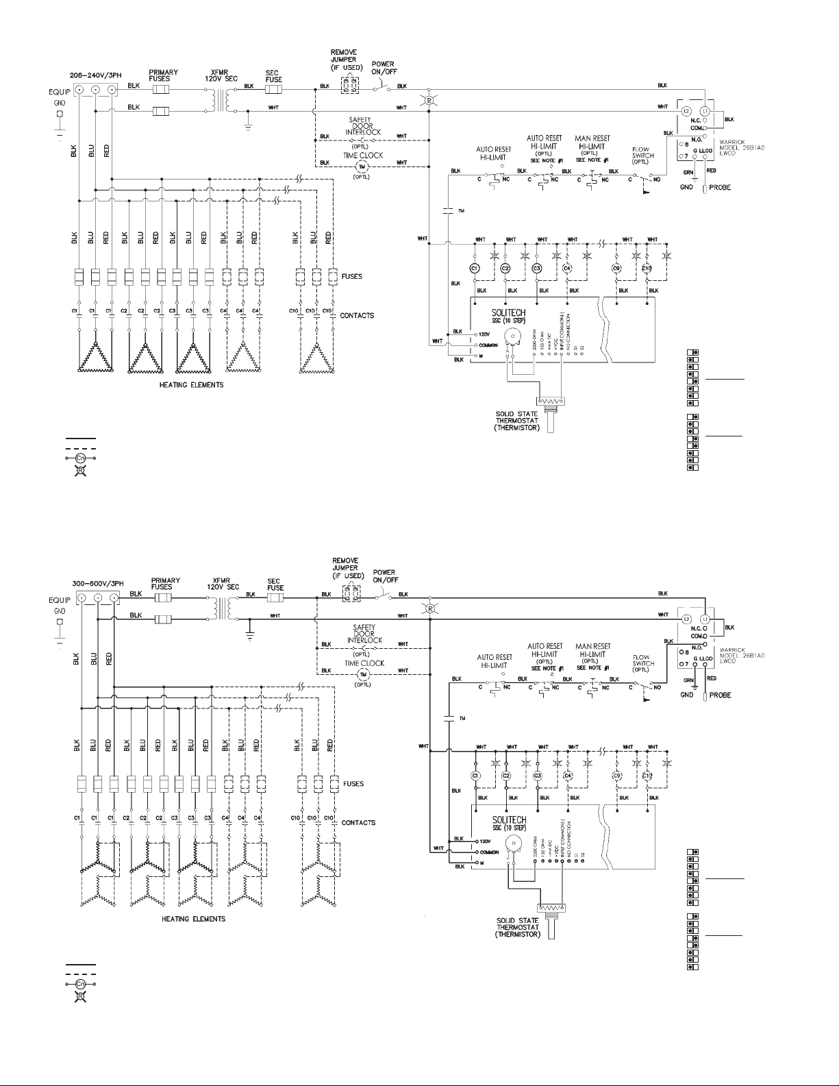
NOTE(S):
1. SUBSTITUTE A MANUAL RESET HLMT SWITCH FOR ONE(1) OF
THE AUTO RESET HLMT SWITCHES.
STD. WIRING
OPTIONAL OR FIELD WIRING AS REQ’D
CONTACTOR COIL
INDICATION LIGHT
THREE PHASE DELTA WITH STEP CONTROL
DIAGRAM 3.
1 OFF ON 2200
ON 135
2 OFF
ON 4-20MA
3 OFF
ON 0-10VDC
4 OFF
PROP
5 DS
UN
6 PROG
VER
7 OFF
MN
8 SEC
DELAY 1
1
DELAY 2
2
DELAY 3
3
-1-
4
-2-
5
-4-
6
-5-
7
-16-
8
THE ABOVE DIP SWITCH SETTINGS
ARE AN EXAMPLE FOR THE FOLLOWING:
2200 OHM
PROPORTIONAL
PROGRESSIVE
VERNER “OFF”
SECONDS
10 SECOND
3 STAGE
INPUTS
DELAYSTAGES
NOTE(S):
1. SUBSTITUTE A MANUAL RESET HLMT SWITCH FOR ONE(1) OF
THE AUTO RESET HLMT SWITCHES.
STD. WIRING
OPTIONAL OR FIELD WIRING AS REQ’D
CONTACTOR COIL
INDICATION LIGHT
THREE PHASE WYE WITH STEP CONTROL
DIAGRAM 4.
14
1 OFF ON 2200
ON 135
2 OFF
ON 4-20MA
3 OFF
ON 0-10VDC
4 OFF
PROP
5 DS
UN
6 PROG
VER
7 OFF
MN
8 SEC
DELAY 1
1
DELAY 2
2
DELAY 3
3
-1-
4
-2-
5
-4-
6
-5-
7
-16-
8
THE ABOVE DIP SWITCH SETTINGS
ARE AN EXAMPLE FOR THE FOLLOWING:
2200 OHM
PROPORTIONAL
PROGRESSIVE
VERNER “OFF”
SECONDS
10 SECOND
3 STAGE
INPUTS
DELAYSTAGES
Page 15
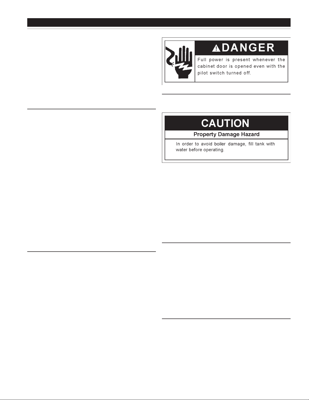
OPERATION
IMPORTANT
IT IS RECOMMENDED THAT A QUALIFIED SERVICE TECHNICIAN
PERFORM THE INITIAL FIRING OF THE BOILER. AT THIS TIME
THE USER SHOULD NOT HESITATE TO ASK THE TECHNICIAN
ANY QUESTIONS WHICH THEY MAY HAVE IN REGARD TO THE
OPERATION AND MAINTENANCE OF THE BOILER.
BEFORE FILLING THE SYSTEM FOR OPERATION the hot water
system should be internally cleaned and ushed to remove any
contaminants which may have accumulated during installation. See
section of this manual titled SYSTEM CLEANING.
GENERAL
Never operate the heating elements without being certain the boiler
is lled with water and a pressure relief valve is installed in the relief
valve opening provided.
LWCO
An electronic type low water cutoff is provided on all boilers as
standard equipment. The water probe is installed near the top of the
tank to monitor the presence of water. The control circuit is opened if
the water level is below this point.
FILLING THE BOILER
Refer to SYSTEM CLEANING section for preparing the system prior
to nal lling and operation.
Power On/Off
The pilot switch on the cabinet front permits the boiler to be turned
on and off without having to operate the electrical disconnect
switch. Additional switches may be provided for manually operating
contactor coils.
Relief Valve
An ASME rated pressure relief valve is furnished with the boiler. A
tting for the relief valve is provided in the top of the boiler. A drain
line from the relief valve should terminate near a suitable drain. Do
not thread, plug, or cap the end of the drain line.
The pressure setting of the relief valve should not exceed the pressure
capacity of any component in the system including the boiler.
HIGH TEMPERATURE LIMITS
Automatic High Limit
The boiler control circuit contains two high temperature cutoff
switches. This device shuts off the heating elements if excessive
water temperatures are reached. The high temperature cutoff has
an adjustable range of 100° to 240°F and automatically resets on a
drop of temperature.
Manual High Limit (Optional)
A manual reset high limit may be in the control circuit in addition
to the automatic high limit previously described. The control has
an adjustable range of 110°F to 290°F and activates and locks
on a temperature increase. When the temperature declines the
manual reset high limit can be reset. A manual reset high limit
is an optional substitution for one of the automatic high limits
mentioned above.
Hard Water: in areas which have hard water it may be desirable
to ll the system with soft water and/or provide water treatment as
recommended by a consultant familiar with local conditions. In this way
harmful water scale build-up on the heating elements is minimized.
1. Close the boiler drain valve and system valves as necessary.
2. Open a vent in the highest point of the system to allow the air to escape.
3. Fully open the make-up water inlet valve. Fill the boiler and piping.
4. Close the vent as water starts to ow from the opening. Place the
make-up water valve in the desired position. The boiler is now
ready for START UP and TEMPERATURE REGULATION if being
placed in operation for the rst time.
INITIAL START UP
The following checks should be made by the installer when the boiler
is placed into operation for the rst time:
1. Check all factory and eld made water and electrical connections
for tightness.
• Repair water leaks and tighten electrical connections as necessary.
2. Turn on the electrical disconnect switch and pilot switch(es)
mounted on the boiler cabinet.
3. Observe the operation of the boiler during the rst heating cycle.
• Temperature control and contactor operation should be checked by
allowing the boiler to come up to temperature and shutoff automatically.
TEMPERATURE REGULATION
Always turn off the electricity at the electrical disconnect switch when
making a temperature control adjustment.
The manual reset button is located on the high limit switch which is
located in the control panel.
It is suggested the temperature adjustment be turned to the lowest
setting which satises the hot water requirements of the system.
15
Page 16
TEMPERATURE CONTROLS
The boilers covered in this instruction manual are equipped with
(adjustable) thermostat or step control to regulate water temperature
and other controls to provide safety features. See the wiring diagrams
on page 13 & 14 and/or literature included with this manual for
additional information.
Hot water temperatures required for automatic dishwasher and
laundry use can cause scald burns resulting in serious personal injury
and/or death. The temperature at which injury occurs varies with the
person’s age and duration of exposure. The slower response time
of children, the elderly or disabled persons increases the hazards to
them. Never allow small children to use a hot water tap or draw their
own bath water. Never leave a child or disabled person unattended
in a bathtub or shower. The boiler should be located in an area where
the general public does not have access to set temperatures.
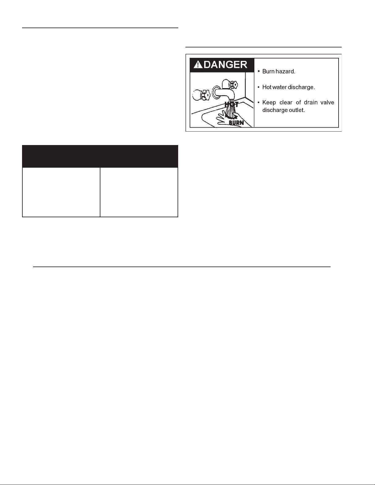
Figure 1. shows the approximate time-to-burn relationship for normal
adult skin.
Water Temperature
Time to Produce 2nd & 3rd
Degree Burns on Adult Skin
Always close and lock the cabinet door after making a temperature
adjustment. Turn on electricity.
DRAINING
The boiler must be drained if it is to be shut down and exposed to
freezing temperatures. Maintenance and service procedures may
also require draining the boiler.
1. Turn off the electrical disconnect switch.
180°F (82°C)
160°F (82°C)
150°F (82°C)
140°F (82°C)
130°F (82°C)
120°F (82°C)
80°F (82°C)
Nearly Instantaneous
About 1/2 second
About 1-1/2 seconds
Less than 5 seconds
About 30 seconds
More than 5 minutes
- - - - - - - - - - - - - - - - -
FIGURE 1.
• Additional instructional literature is provided with the boiler for
adjusting this control.
2. Open a nearby outlet until the water is no longer hot and close the
make-up water valve and system valves as necessary.
3. Open a nearby outlet to vent the parts of the system being drained.
4. Open the boiler drain valve.
5. If the boiler is being drained for an extended shutdown, it is
suggested the drain valve be left open during this period.
• Follow FILLING instructions to restore boiler to service.
16
Page 17
MAINTENANCE
Boiler maintenance includes periodic tank ushing and cleaning, and
removal of lime scale from the heating elements. Circulating pumps
should be oiled.
MAINTENANCE SCHEDULE
Component Operation Interval Required
Tank
Elements
Circulating Pump(s) Oiling Per pump makers instructions
Pressure Relief
Valve Test
Flushing Monthly
Sediment
Removal
Lime Scale
Removal
Manually
Operate
As Needed
As Needed
Anually
UN•LIME
Delimer and
element gaskets
®
PRESSURE RELIEF VALVE TEST
Failuretocleanthesystemmaycause:
1. Poor heating due to formation of gas.
• Residential pipe dope, thread cutting oil, solder ux, dirt and other
foreign materials breakdown to form gas. This is indicated by a
continuing need for purging even through the system is “closed”.
2. Pump seal leakage.
• Acidic water (low pH) and contamination such as soil and sand
result in premature or recurring pump seal failures.
3. Automatic air valve leakage.
• Contaminants cause sticky sealing surfaces and result in leakage.
4. Relief valve operation.
• Gas formation increases system pressure and relief valve spillage.
5. Water leaks at joints and ttings.
• Corrosion and eventual failure of connections occur when
system pH is low.
6. Noisy operation.
• Heat transfer surfaces can be fouled with dirty, oily water. This
plus gas lead to noisy water circulation.
FLUSHING
The pressure relief valve must be manually operated at least once a
year. Caution should be taken to ensure that (1) no one is in front of
or around the outlet of the pressure relief valve discharge line, and
(2) the water manually discharged will not cause any bodily injury or
property damage because the water may be extremely hot.
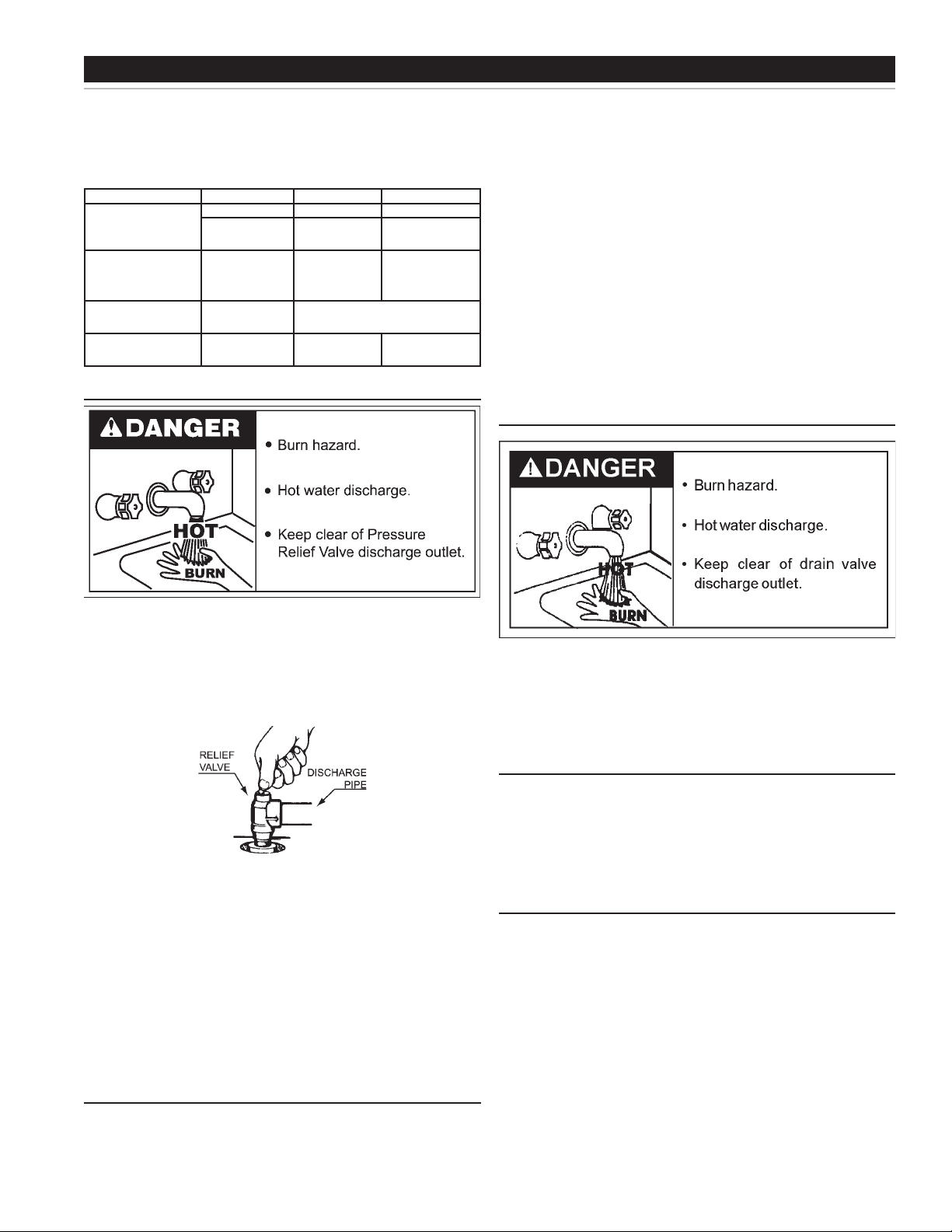
To test the relief valve, lift the lever at the end of the valve several times,
see Figure 2. The valve should seat properly and operate freely.
FIGURE 2.
If after manually operating the valve, it fails to completely reset and
continues to release water, turn off power to the boiler at the main
disconnect switch or breaker. Close the cold water inlet to the boiler and
follow the draining instructions in this manual to drain the boiler. Should
the relief valve need to be replaced, call the toll free phone number
listed on the back of this manual for further technical assistance.
Tank ushing and circulating pump lubrication should be performed
in accordance with the above schedule. Tank sediment removal and
element lime scale removal must be performed when needed as
determined by period inspections. Following are the instructions for
performing recommended maintenance.
1. Turn off the electrical disconnect switch.
2. Open the boiler drain valve. Allow water to ow to an open drain
until it runs clean. Do not come in contact with the water being
drained as it may be very hot.
3. Close the drain valve when nished ushing.
4. Turn on the electrical disconnect switch.
SEDIMENT REMOVAL
Water borne impurities consist of ne particles of soil and sand which
settle out and form a layer of sediment on the bottom of the tank. In time,
if not removed, the level of sediment might reach the heating elements.
For convenience, sediment removal and element lime scale removal
should be performed at the same time as follows:
WATER AND LIME SCALE REMOVAL
Water and lime scale accumulations on the heating elements is a
normal condition, common to all immersion type elements. Factors
which affect the amount of this formation are:
1. Amount of make-up water used. As the volume of make-up water
heated increases, more scale results.
2. Water temperature. As the temperature of the water is increased,
more scale is deposited on the elements.
3. Characteristics of water supply. Regardless of water treatment,
the elements should be examined regularly.
SYSTEM CLEANING
The hot water system should be internally cleaned and ushed to
remove contaminants which may have accumulated during installation.
System cleaning provides chemical stability necessary for component
life and system performance.
Water scale accumulations may cause noises to occur during operation.
It is recommended that a lower heating element be removed
periodically for examination. If it is scaled, all of the elements should
be removed and cleaned. If the tank bottom has an accumulation of
sediment, it should be cleaned.
17
Page 18

Lime scale should be removed from the elements by dissolving the
accumulation in UN•LIME® delimer. UN•LIME is a non-muriatic
delimer, available through your dealer or distributor. Do not use
muratic or hydrochloric acid base deliming solutions to remove lime
scale from the elements. Do not pour delimer into tank.
All models:
1. Turn off electrical disconnect switch.
2. Drain the boiler following DRAINING instructions.
3. Remove the cabinet panel which covers the heating elements.
• Remove insulation as necessary to reach the element area.
4. Remove the bolts from each element and remove the elements
from the opening.
• Disconnect element wiring as necessary.
• Use a twisting, pulling action to remove elements scaled beyond
the size of the tank opening.
• Brush loose scale from elements.
• Silicates, sulfates and aluminates must be removed by scraping or
other mechanical means. Lime scale dissolvents will not remove
these types of scale which are occasionally encountered.
5. Lime scale removal:
TROUBLESHOOTING CHECKLIST
• Place limed ends of heating elements into UN•LIME delimer
and allow scale to dissolve. Do not permit delimer or water to
contact heating element electrical terminals.
6. Flush cleaned ends of elements with water when deliming or
cleaning is completed.
7. Remove sediment and scale from the tank bottom through the
tank cleanout.
• The make-up water valve and boiler drain valve may be opened
to ush during the cleanout process.
8. Clean remaining gasket material from tank and element anges. Do
not reuse original element gasket. The element gasket is Part No.
5109.
9. Replace elements as follows:
• Put a new gasket on each element.
• Install into tank opening.
• Uniformly tighten element bolts. Torque to approximately 32 ft /lbs.
10. Connect element wiring as necessary.
11. Follow FILLING instructions to restore boiler to service.
• Check for water leaks around elements and proper
operation when boiler is lled.
• Replace insulation and cabinet panel.
Before calling for service, check the following points to see if the
cause of trouble can be identied and corrected. Reviewing this
checklist may eliminate the need of a service call and quickly restore
the boiler to service. The illustration on page 5 identies the location
of most of the boiler components.
BE SURE TO TURN OFF THE ELECTRICITY WHEN CHECKING
EQUIPMENT.
Not enough or no hot water
1. Be certain the electrical disconnect switch serving the boiler is in the
ON position. The pilot switch(es) on the cabinet front should be on.
• In some installations the boiler electrical service may be limited
by the power company or boiler controls. If the boiler operates
on a controlled circuit heat may be effected.
2. Check the fuses.
• The electrical disconnect switch usually contains fuses.
• The boiler has fuses located behind the cabinet door, see page
5 for location.
3. If the water was excessively hot, and is now cold, the high
temperature cutoff may have operated (manual reset equipped
models).
• To reset, turn off electricity and remove the back panel and push
the reset button.
• Repeated operation of the high temperature cutoff should be
investigated by your servicer.
4. The capacity of the boiler may have been exceeded by a large
demand for heat.
• Large demands require a recovery period to restore water
temperature.
5. Sediment or lime scale may be affecting boiler operation. Refer to
MAINTENANCE for details.
Water is too hot
sizzling and hissing noises when the boiler is operating.
• The sounds are normal , however, the tank bottom and elements
should be cleaned. Refer to MAINTENANCE for details.
2. Some of the electrical components of the boiler make sounds
which are normal.
• Contactors will “click” or snap as the boiler starts and stops.
• Transformers and contactors often hum.
Water leakage is suspected
1. Check to see if the drain valve is tightly closed.
2. If the outlet of the relief valve is leaking it may represent:
• Excessive water pressure or air in the system.
• Faulty relief valve.
3. Examine the ange area of the elements and tank cleanout for
gasket leakage.
• Tighten the bolts or, if necessary, follow the WATER AND LIME
SCALE REMOVAL procedure to replace the gaskets.
SYSTEM WATER TEST
System water test
Review SYSTEM CLEANING section, for a description of six problems
which result from loss of system chemical stability. Chemical stability
is checked by:
1. Draw off water from system. Is it dirty, discolored or odorous?
2. What is the pH of the system water? It should be neutral or slightly
alkaline.
3. Does “air” purged from system vents burn? If so, the “air” is
actually gas.
If any of the above conditions are present, all waterways should be
cleaned and the water adjusted to an alkaline condition.
1. Refer to TEMPERATURE REGULATION.
Boiler makes sounds
1. Sediment or lime scale accumulation on the elements may cause
Ifyoucannotidentifyorcorrectthesourceofmalfunction:
1. Place the boiler electrical disconnect switch in the OFF position.
2. Close the make-up water inlet valve to the boiler.
3. Contact your servicer.
18
Page 19

SW-37 THRU SW-670 ELECTRIC HOT WATER BOILER LIMITED WARRANTY
State Water Heaters, the warrantor, extends the following LIMITED WARRANTY to the owner of this boiler.
1. THE TANK
If the tank in this boiler shall prove upon examination by the warrantor to have leaked due to natural corrosion from water therein, during the FIRST
year after initial installation, the warrantor will at its option, repair it or provide a replacement tank less elements and controls of equivalent size and
then current model. Some government agencies are requiring energy efcient standards for boilers. In the event regulations prohibit sale of a model
of equivalent size and construction, State Water Heaters will provide a model which complies with the regulations of your area, in which case the
consumer will be charged the difference in price between the like replacement and the energy efcient model required. The warranty on the repair or
replacement of the part, portion or tank will be limited to the unexpired term of the original warranty.
2. ALL OTHER PARTS
If within ONE year after initial installation of this boiler, any part or portion shall prove upon examination by the warrantor to be defective in material
or workmanship, the warrantor will repair or replace such part or portion at its option.
3. CONDITIONS AND EXPECTATIONS
This warranty shall apply only when the boiler is installed in accordance with local plumbing and building codes, ordinances and regulations,
the printed instructions provided with it and good industry practices. In addition, a pressure relief valve, approved by the American Society of
Mechanical Engineers, must have been installed.
This warranty shall apply only when the boiler is used:
a. (1) at temperatures not exceeding the maximum setting of its control;
(2) at water pressure not exceeding the working pressure shown on the boiler;
(3) when lled with water, free to circulate at all times and with the tank free of damaging scale deposits;
(4) in a noncorrosive and non-contaminated atmosphere;
(5) in its original installation location;
(6) in the United States, its territories or possessions, and Canada;
(7) when operated free of the damaging effects of uncontrolled thermal expansion and/or water hammer.
b. Any accident to the boiler, any misuse, abuse (including freezing) or alteration of it, any operation of it in a modied form will void this warranty.
4. SERVICE AND REPAIR EXPENSE
Under this limited warranty the warrantor will provide only repair or a replacement tank or part thereof. The owner is responsible for all other costs.
Such costs may include but are not limited to:
a. Labor charges for service, removal, repair, or reinstallation of the tank or any component part;
b. Shipping, delivery, handling, and administrative charges for forwarding the new tank or replacement part from the nearest distributor and
returning the claimed defective tank or part to such distributor.
c. All cost necessary or incidental for any materials and/or permits required for installation of the replacement tank or part.
5. LIMITATION ON IMPLIED WARRANTIES
Implied warranties, including any warranty of merchantability imposed on the sale of this boiler under state law are limited to one (1) year duration for
the tank or any of its parts. Some states do not allow limitations on how long an implied warranty lasts, so the above limitation may not apply to you.
6. CLAIM PROCEDURE
Any claim under this warranty should be initiated with the dealer who sold the boiler, or with any other dealer handling the warrantor’s products. If
this is not practicable, the owner should contact:
U.S. Customers Canadian Customers
State Water Heaters State Water Heaters
500 Tennessee Waltz Parkway 599 Hill St. W.
Ashland City, TN 37015 Fergus, ON N1M 2X1
Telephone: 800-365-0024 Attn: Warranty
Telephone: 888-479-9283
a. The warrantor will only honor replacement with identical or similar tank or parts thereof which are manufactured or distributed by the warrantor.
b. Dealer replacements are made subject to in-warranty validation by warrantor.
7. DISCLAIMER
NO OTHER EXPRESS WARRANTY HAS BEEN OR WILL BE MADE IN BEHALF OF THE WARRANTOR WITH RESPECT TO THE BOILER OR
THE INSTALLATION, OPERATION, REPAIR OR REPLACEMENT OF THE TANK OR PARTS. THE WARRANTOR SHALL NOT BE RESPONSIBLE
FOR WATER DAMAGE, LOSS OF USE OF THE UNIT, INCONVENIENCE, LOSS OR DAMAGE TO PERSONAL PROPERTY, OR OTHER
CONSEQUENTIAL DAMAGE. THE WARRANTOR SHALL NOT BE LIABLE BY VIRTUE OF THIS WARRANTY OR OTHERWISE FOR DAMAGE
TO ANY PERSONS OR PROPERTY, WHETHER DIRECT OR INDIRECT, AND WHETHER ARISING IN CONTRACT OR IN TORT.
a. Some states do not allow the exclusion or limitation of the incidental or consequential damage, so the above limitation or exclusion may not apply
to you.
b. This warranty gives you specic legal rights, and you may also have other rights which vary from state to state.
Fill in the following for your own reference. Keep it. Registration is not a condition of warranty. The model and ASME numbers are found on the boiler’s rating plate.
Model No. ________________________________________________ ASME No. _______________________Date Installed _________________
Dealer’s Name _________________________________________________________________________________________________________
Dealer’s Address ___________________________________________________________________________Phone No. ___________________
City and State _____________________________________________________________________________Zip _________________________
KEEP THIS WARRANTY AND MANUAL POSTED ADJACENT TO THE BOILER FOR FUTURE REFERENCE WHENEVER MAINTENANCE,
ADJUSTMENT OR SERVICE IS REQUIRED. BE SURE YOUR DEALER HAS FILLED IN THIS WARRANTY.
19
Page 20

A DIVISION OF A. O. SMITH CORPORATION
RENTON, WASHINGTON
Technical Support: 800 527-1953
Parts Department: 800 433-2515
www.statewaterheaters.com
 Loading...