

Page 1
C O M M E R C I A L
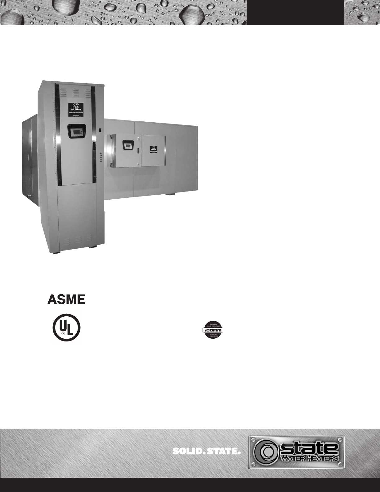
COMMERCIAL ELECTRIC
WATER HEATERS
STANDARD FEATURES
Advanced Electronic Control
State’s new propriety electronic water heater control,
provides precise + or - 1ºF temperature control, that is
ideal for industrial and food service applications where
exact temperatures of hot water are needed.
Glass-Lined Tank
•Tank interior is coated with glass specially developed
for use in water heaters. Tanks rated at 125 psi
working pressure; 150 psi or 160 psi working pressure
is optional. Vermin proof fiber glass insulation reduces
costly heat loss. Constructed to Section IV of ASME
code, and UL standards. Tanks have channel skid
base. A 4” x 6” handhole is furnished on 500, 600 and
700-gallon models; 11” x 15” manhole is furnished
on 800-gallon and larger sizes.
Fusing
•Control and power circuit fusing to meet N.E.C.
Compliance
•Meets or exceeds the standby loss requirements of the
U.S. Department of Energy and current edition of
ASHRAE/IESNA 90.1.
SEV-150-10,000
SEH-200-10,000
•Plain Text – Animated icons display detailed
operational and diagnostic information. Fault or Alert
messages appear if an operational issue occurs.
•LowWater Cut Off – Factory standard on board low
water cut-off uses a remote electronic immersion type
probe to prevent energizing of the elements in the
event of low water condition and eliminates accidental
dry firing.
•Progressive Modulating – Sizes the input of available
elements to match current load conditions. Rotates
and lead lags element loads to provide long life and
equal wear.
•Economy Mode Operation – Control system
automatically lowers the operating set point by a
programmed value during user defined time periods.
Seven-day clock may be programmed for night set
back and or weekend shutdown to reduce operating
cost and save money.
•iCOMM™ Compatible - Units can be
monitored from remote locations. Call
1.888.WATER02 for more information.
Note: Units over 150KW use analog controls.
SSoolliidd SSttaattee MMoodduullaattiinngg SStteepp CCoonnttrrooll
(A
ll Models 180KW and up)
• Solid state electronic control device that modulates input
to match load through progressive sequencing of steps
(up to 20 steps with maximum of one per contactor).
Incoloy Immersion Heaters
•Heavy-duty medium watt density elements
(three/immersion heater) have incoloy sheathing:
provide excellent protection against oxidation and
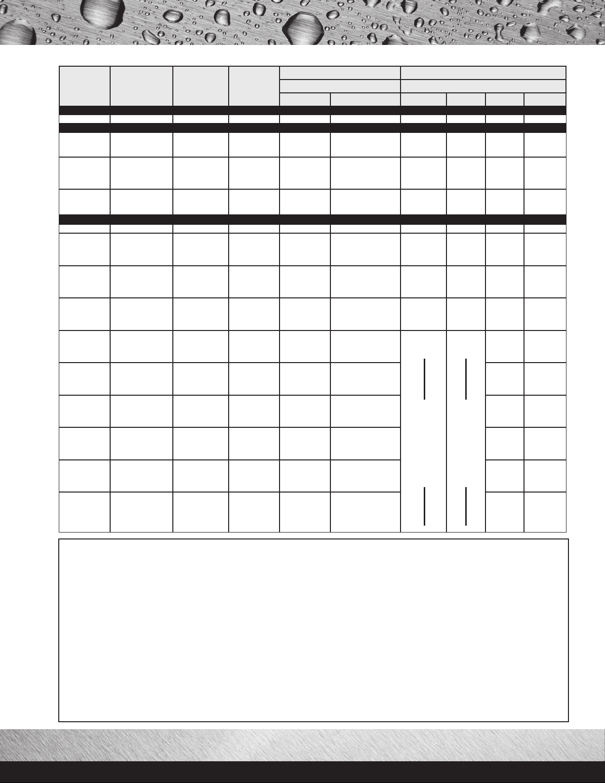
scaling. The input ranges from 15KW to 3000KW
(see accompanying chart).
Magnetic Contactor(s)
•Heavy duty UL rated for 100,000 cycles.
OTHER STANDARD FEATURES
•Color-coded circuitry for easier servicing
•Anode rods for maximum corrosion protection
•Standard voltages include 208, 240, 480, 600 volt
single or three-phase.
•For other voltages consult factory.
•Factory-installed terminal block(s)
•Cabinet has baked enamel finish
•Prewired element terminal leads
•Temperature and pressure relief valve
•2” dial temperature gauge
Optional Dual-Energy
Source Capability
•Provides emergency back up energy source or
winter/summer boiler operation. Can be specified with
optional water to water or steam to water heat
exchangers. Both single and double-wall heat
exchangers are available. Complete control packages
can be factory-installed for hook-up and run capability.
Limited Warranty Outline
•If the tank should leak any time during the first three
years, under the terms of the warranty, State will repair
or replace the heater; installation, labor, handling
repair or replace the heater; installation, labor,
handling and local delivery extra.
THIS OUTLINE IS NOT A WARRANTY. For
complete information, consult the written warranty or
State Customer Care Center. Warranty does not apply
to product installed outside of the United States of
America or its territorial possessions and Canada.
For more information on Electric Water Heaters, contact:
State Water Heaters
500 Tennessee Waltz Parkway
Ashland City, TN 37015
800-365-0024 Toll-free USA
www.statewaterheaters.com
April 2010 SCESS00208
Page 2
®
Commercial Electric Water
Heaters
State
Model
Number
Nominal
Gallon
Capacity
Maximum
KW
Input
Height
A
Width
(Length) BDepth
C D E
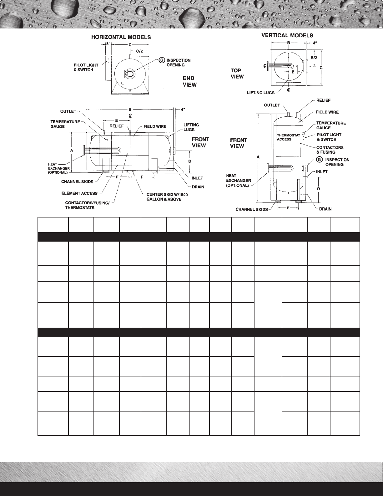
HORIZONTAL ELECTRIC STORAGE HEATER
SEH-200
SEH-250
SEH-300
SEH-350
SEH-400
SEH-500
SEH-600
SEH-700
SEH-800
SEH-1000
SEH-1250
SEH-1500
SEH-2000
SEH-3000
SEH-5000
SEH-7500
SEH-10,000
200
250
300
350
400
500
600
700
800
1000
1250
1500
2000
3000
5000
7500
10,000
180
240
300
330
390
480
600
690
780
990
1200
1500
1980
3000
3000
3000
3000
38-1/2
38-1/2
44-1/2
44-1/2
44-1/2
51
51
51
57
61
61
61
70
76
82
94
106
77
91
81
93
100
94
109
121
111
111
138
150
177
211
296
317
345
36
36
42
42
42
48
48
48
54
60
60
60
66
72
78
90
102
10-1/2
10-1/2
8-1/4
8-1/4
8-1/4
14
14
14
16-1/2
16-1/2
16-1/2
16-1/2
20
20
20-1/2
21-1/2
22
17-1/2
24
17
23
26-1/2
24
32
38
32
29-1/2
43
50
60
72-1/2
113-1/2
121
132
VERTICAL ELECTRIC STORAGE HEATER
SEV-140
SEV-150
SEV-150L
SEV-200
SEV-250
SEV-300
SEV-350
SEV-400
SEV-500
SEV-600
SEV-700
SEV-800
SEV-1000
SEV-1250
SEV-1500
SEV-2000
SEV-3000
SEV-5000
SEV-7500
SEV-10,000
*Complete Model Number includes the desired KW at end, e.g.: SEV-500-120 when KW = 120.
**Size may vary according to KW input.
Minimum installation clearances required. 30” from front, 12” from top, and 24” from right side.
140
150
150
200
250
300
350
400
500
600
700
800
1000
1250
1500
2000
3000
5000
7500
10,000
150
150
150
180
240
300
330
390
480
600
690
780
990
1200
1500
1980
3000
3000
3000
3000
83-1/2
83-1/2
59-1/2
79-1/2
93
83-1/2
95-1/2
102-1/2
97
112
124
116
116
143
155
183
217
309
330
358
30
30
36
36
36
42
42
42
48
48
48
54
60
60
60
66
72
78
90
102
37
37
43
43
43
49
49
49
55
55
55
61
67
67
67
73
79
85
97
109
16
16
17-1/2
17-1/2
17-1/2
19
19
19
21
21
21
23
24-1/2
24-1/2
24-1/2
25
27-1/2
30
30
30
6
6
6
6
6
6
6
6
6
6
6
8
10
10
10
12
14
14
14
14
Skid
Spacing
F
31
48
36
48
55
48
64
76
64
59
86
98
120
131
195
218
220
17
17
21
21
21
25-1/2
25-1/2
25-1/2
30
30
30
34
38
38
38
42-1/2
47
51
59-1/2
68
Inspection
Opening
G
Optional
4” x 6”
Handhole
11” x 15”
Manhole
Optional
4” x 6”
Handhole
11” x 15”
Manhole
Inlet
Outlet
Opening
1-1/2
1-1/2
2
2
2
2
2
2
2
3
3
3
3
3
3
4
4
1-1/4
1-1/4
1-1/4
1-1/2
1-1/2
2
2
2
2
2
2
2
3
3
3
3
3
3
4
4
Drain
Opening
3/4
3/4
3/4
3/4
3/4
1-1/4
1-1/4
1-1/4
1-1/2
1-1/2
1-1/2
1-1/2
2
2
2
2
2
3/4
3/4
3/4
3/4
3/4
3/4
3/4
3/4
1-1/4
1-1/4
1-1/4
1-1/2
1-1/2
1-1/2
1-1/2
2
2
2
2
2
Valve
Opening**
3/4
1
1
1
1
1
1
1
1
1
1
1
1-1/4
1-1/2
1-1/2
1-1/2
1-1/2
3/4
3/4
3/4
3/4
1
1
1
1
1
1
1
1
1
1
1
1
1-1/2
1-1/2
1-1/2
1-1/2
SCESS00208 April 2010 Page 2 of 4 © 2010 State Industries, Inc.
Page 3
STANDARD
KW RATINGS
NUMBER OF
IMMERSION
HEATERS
BTU INPUT
& OUTPUT
GPH
RECOVER
100°F RISE
NUMBER OF 50A CONTACTORS AMPERAGE DRAW
THREE-PHASE THREE-PHASE
208V, 240V 480V, 600V 208V 240V 480V 600V
XI ON/OFF
15 1-15KW 51,195 61 11 42 37 19 15
XI PROGRESSIVE
24
30
36
2-12KW
2-15KW
3-12KW
81,912
102,390
122,868
98
123
147
2
2
3
2
2
3
67
83
100
58
72
87
27
36
43
23
29
35
45
60
75
90
3-15KW
4-15KW
5-15KW
6-15KW
153,585
204,720
255,975
307,170
184
246
307
369
3
4
5
6
3
4
5
5
126
167
208
250
109
145
181
217
54
72
90
109
44
58
72
87
105
120
150
7-15KW
8-15KW
10-15KW
358,365
409,560
511,950
430
492
615
7
8
10
5
5
5
292
333
416
253
289
361
127
145
180
101
115
144
SOLID STATE STEP CONTROL
180 12-15KW 614,340 738 12 6 499 433 217 173
210
240
270
300
14-15KW
16-15KW
18-15KW
20-15KW
716,730
819,120
921,510
1,023,900
861
984
1,107
1,230
14
16
18
20
7
8
9
10
583
666
750
832
505
577
650
722
253
289
325
361
202
231
260
289
330
360
390
420
22-15KW
24-15KW
26-15KW
28-15KW
1,126,290
1,228,680
1,331,070
1,433,460
1,353
1,476
1,599
1,722
22
24
26
28
11
12
13
14
916
999
1,083
1,166
794
866
938
1,010
397
433
469
505
318
346
375
404
450
480
510
540
30-15KW
32-15KW
34-15KW
36-15KW
1,535,850
1,638,240
1,740,630
1,843,020
1,845
1,968
2,091
2,214
30
32
34
36
15
16
17
18
1,249
1,332
1,416
1,499
1,083
1,155
1,227
1,299
542
578
613
650
433
462
491
520
570
600
630
660
38-15KW
40-15KW
42-15KW
44-15KW
1,945,410
2,047,800
2,150,190
2,252,580
2,337
2,460
2,583
2,706
38
40
19
20
21
22
1,582
1,664
1,371
1,443
686
722
758
794
548
577
606
635
690
720
810
900
46-15KW
48-15KW
54-15KW
60-15KW
2,345,970
2,457,360
2,764,530
3,071,700
2,829
2,952
3,321
3,690
23
24
27
30
830
866
974
1,083
664
693
779
866
990
1080
1170
1260
66-15KW
72-15KW
78-15KW
84-15KW
3,378,870
3,686,040
3,993,210
4,300,380
4,059
4,428
4,797
5,166
33
36
39
42
830
866
974
1,083
953
1,039
1,126
1,213
1350
1440
1530
1620
90-15KW
96-15KW
102-15KW
108-15KW
4,607,550
4,914,720
5,221,890
5,529,060
5,535
5,904
6,273
6,642
45
48
51
54
1,191
1,299
1,408
1,516
1,300
1,386
1,473
1,559
1800
1980
2040
2220
120-15KW
132-15KW
136-15KW
148-15KW
6,141,600
6,757,740
6,962,520
7,576,860
7,380
8,118
8,364
9,102
60
66
68
74
1,624
1,732
1,841
1,949
1,732
1,905
1,963
2,136
2250
2400
2540
2820
3000
150-15KW
160-15KW
176-15KW
188-15KW
200-15KW
7,679,250
8,188,800
9,010,320
9,624,660
10,236,000
9,225
9,840
10,824
11,562
12,300
75
80
88
94
100
2,707
2,887
3,175
3,392
3,608
2,165
2,310
2,540
2,714
2,887
Not Recommended
Not Recommended
The heater(s) shall be State Large Volume Electric Water Heater Model Number ___________________ or an approved equal. Heater(s) shall be
rated at _______ KW, _______ V, _______ phase, 60 cycle AC. The heater shall be for (vertical/horizontal) installation with lifting lugs and channel
skid base. Vessel shall be constructed to Section IV of the ASME Code for 125 psi working pressure. Vessel shall be glass-lined with anodic
protection. Entire vessel and electrical controls are to be encased in a rectangular sheet metal enclosure with baked enamel finish. Tank to be
insulated with fiberglass insulation. Separate 2" dial type temperature gauge will be mounted on the front of the enclosure. Enclosure to have
hinged locking door over electric controls. There shall be ____________ individually replaceable _______ KW, 4 bolt flange mounted, incoloy
sheathed heating elements each complete with prewired terminal leads. These elements will be switched by magnetic contactors which are
operated by a 120V fused control circuit protected by manual reset high limit. Control circuit is activated by a master pilot switch and electronic
low water cutoff. The optional modulating control of the contacts shall be in _______ stages through solid state modulating step control which
will balance the water heating input to the demand. This control shall prevent the entire electrical load from being switched on instantaneously.
The control shall have even load progressive sequencing which utilizes the "first on, first off" principle thereby equalizing the operating time
of heating elements and contactors. Each magnetic contactor and heating element circuit will be protected by a maximum of 60 amp cartridge
type fuses with a minimum of 100,000 amp interrupting capacity. The entire water heating package shall be prewired to solderless terminal
lugs, factory tested, complete with ASME temperature and pressure relief valve and bear the Underwriters' Laboratories label. Heater(s) shall
have a 3 year limited warranty as outlined in the written warranty. Fully illustrated instruction manual included.
SCESS00208 April 2010 Page 3 of 4 © 2010 State Industries, Inc.
SAMPLE SPECIFICATIONS
Page 4

C O M M E R C I A L
COMMERCIAL ELECTRIC
WATER HEATER S
OPTIONS
TANK LININGS
CEMENT – A special formulation of cement providing excellent
corrosion protection. Available on 200 gallon and larger tanks.
EPOXY – A solventless two component epoxy lining applied to a
minimum ten-mil (.010”) dry thickness. Available on 200 gallon
and larger tanks.
SPECIAL CONSTRUCTION
STAINLESS STEEL VESSELS – Are available for deionized
water. Built with stainless steel under rules of Section IV of the
ASME Boiler and Pressure Vessel Code for operation on deionized
water having a minimum specific resistivity of 10 megohm/cm.
150 OR 160 PSI WORKING PRESSURE – Must be
specified at time of order.
OTHER OPTIONAL FEATURES
TEMPERATURE AND PRESSURE RELIEF VALVES –
For working pressures other than standard;
consult factory.
HORIZONTAL OR VERTICAL – See specifications, most
gallon capacities may be obtained in vertical or horizontal
construction.
CIRCULATING PUMP PACKAGE – Circulating pump and
piping sized to turn over entire storage capacity of tank once each
hour. Recommended to optimize available water at temperature in
horizontal tanks particularly where low draw conditions are
anticipated.
OPTIONAL INTERNATIONAL VOLTAGES – 380 and 415
volts three-phase.
3-1/2” DIAL-TYPE PRESSURE GAUGE –
Factory-installed.
3-1/2” DIAL-TYPE TEMPERATURE GAUGE –
Factory-installed.
11” x 15” MANHOLE – Available as option on tanks 700
gallons or smaller.
CONTROL OPTIONS
COPPER TUBE TANK HEATER – Double wall copper tube
tank heaters are designed for heating potable water with both
potable or non-potable liquids or steam, and are specifically
engineered for installation in models SEV and SEH for dual-energy
applications. Tank heaters have a positive fail-safe means of leak
detection in the event of either tube failure to prevent mixture of
heating medium and potable water. Singlewall heat exchangers are
also available.
TERMINAL BLOCKS – Allows for remote connection to
building demand limiter or other functions.
AUTOMATIC RESET HIGH LIMIT – A control that in
the event of high temperature, interrupts power, de-energizing
elements, automatic reset. (Standard with modulating
step control).
INDICATING LIGHTS – Denotes heating stage(s) in operation.
Up to one light per contactor is available.
OVERRIDE SWITCHES – A simple means of load control
allows all or part of unit input to be controlled manually. Up to
one switch per contactor is available
SAFETY DOOR INTERLOCK – Prevents opening of control
panel door when heater power supply is on. NOTE: Once door is
opened heater may be energized if necessary for service diagnosis.
SHUNT TRIP CIRCUIT BREAKER – A safety device
(circuit breaker) which disconnects power to heater in the event
of over-current, high temperature or low water level, breaker
must be manually reset.
CIRCUIT BREAKER – A safety device which disconnects power
to the heater in the event of overcurrent.
For complete information on limited warranties, consult written warranty or contact
the State Customer Care Center at 1-800-365-0024.
State Industries, Inc., reserves the right to make product changes or improvements without prior notice.
For more information on Electric Water Heaters, contact:
State Water Heaters
500 Tennessee Waltz Parkway
Ashland City, TN 37015
800-365-0024 Toll-free USA
www.statewaterheaters.com
SCESS00208 April 2010 Page 4 of 4 © 2010 State Industries, Inc. Printed in U.S.A
 Loading...