

STARVILLE DMX Invader 2420 MK2 User Manual
DMX Invader 2420
MK2
DMX controller
user manual

Musikhaus Thomann e.K.
Treppendorf 30
96138 Burgebrach
Germany
Telephone: +49 (0) 9546 9223-0
E-mail: info@thomann.de
Internet: www.thomann.de
17.10.2013

Table of contents
1 General notes............................................................................................................................................... 5
2 Safety instructions..................................................................................................................................... 7
3 Features....................................................................................................................................................... 11
4 Installation.................................................................................................................................................. 13
5 Connections and operating elements........................................................................................... 17
6 Operating.................................................................................................................................................... 27
6.1 ‘Setting’ menu................................................................................................................................... 27
6.2 Programming mode........................................................................................................................ 65
6.3 Function mode............................................................................................................................... 124
6.4 Fogger operation........................................................................................................................... 137
6.5 Strobe operation............................................................................................................................ 139
7 MIDI functions list................................................................................................................................. 143
8 Notes on creating profiles................................................................................................................ 147
9 Technical specifications..................................................................................................................... 158
Table of contents
DMX Invader 2420 MK2
3
10 Protecting the environment............................................................................................................ 159
Table of contents
DMX controller
4

1
General notes
This user manual contains important information on safe operation of the device. Read and
follow all safety notes and all instructions. Save this manual for future reference. Make sure
that it is available to all persons using this device. If you sell the device, include the manual for
the next owner.
Our products are subject to a process of continuous development. We therefore reserve the
right to make changes without notice.
This section provides an overview of the symbols and signal words used in this user manual.Symbols and signal words
General notes
DMX Invader 2420 MK2
5

Signal word Meaning
DANGER! This combination of symbol and signal word
indicates an immediate dangerous situation
that will result in death or serious injury if it is
not avoided.
NOTICE! This combination of symbol and signal word
indicates a possible dangerous situation that
can result in material and environmental
damage if it is not avoided.
Warning signs Type of danger
Warning – high-voltage.
Warning – danger zone.
General notes
DMX controller
6

2
Safety instructions
This device is intended to be used to control spot lights, dimmers, light effects, moving heads
or other DMX-controlled devices. Use the device only as described in this user manual. Any
other use or use under other operating conditions is considered to be improper and may result
in personal injury or property damage. No liability will be assumed for damages resulting from
improper use.
This device may be used only by persons with sufficient physical, sensorial, and intellectual
abilities and having corresponding knowledge and experience. Other persons may use this
device only if they are supervised or instructed by a person who is responsible for their safety.
Intended use
Safety instructions
DMX Invader 2420 MK2
7

DANGER!
Danger for children
Ensure that plastic bags, packaging, etc. are disposed of properly and are not
within reach of babies and young children. Choking hazard!
Ensure that children do not detach any small parts (e.g. knobs or the like) from
the unit. They could swallow the pieces and choke!
Never let children unattended use electrical devices.
DANGER!
Electric shock caused by high voltages inside
Within the device there are areas where high voltages may be present. Never
remove any covers.
There are no user-serviceable parts inside.
Safety
Safety instructions
DMX controller
8

DANGER!
Electric shock caused by short-circuit
Always use proper ready-made insulated mains cabling (power cord) with a pro‐
tective contact plug. Do not modify the mains cable or the plug. Failure to do so
could result in electric shock/death or fire. If in doubt, seek advice from a regis‐
tered electrician.
NOTICE!
Risk of fire
Do not cover the device nor any ventilation slots. Do not place the device near
any direct heat source. Keep the device away from naked flames.
Safety instructions
DMX Invader 2420 MK2
9
NOTICE!
Operating conditions
This device has been designed for indoor use only. To prevent damage, never
expose the device to any liquid or moisture. Avoid direct sunlight, heavy dirt, and
strong vibrations.
NOTICE!
Power supply
Before connecting the device, ensure that the input voltage (AC outlet) matches
the voltage rating of the device and that the AC outlet is protected by a residual
current circuit breaker. Failure to do so could result in damage to the device and
possibly injure the user.
Unplug the device before electrical storms occur and when it is unused for long
periods of time to reduce the risk of electric shock or fire.
Safety instructions
DMX controller
10
3
Features
This DMX controller is specially suited for professional lighting requirements, such as at events,
on rock stages, for dance bands, trios and duos as well as for mobile DJ applications.
Special features of the device:
n 2 × 3-pin DMX outlets
n 484 DMX channels in total, (including channel 481 for DMX foggers and channels 483-484
for a DMX strobe)
n Fixture library for up to 50 user-defined devices
n 10 preprogrammed, editable Movements with adjustable phase shift
n 60 programmable Chases (200 scenes per Chase)
n 1200 programmable Scenes (60 banks à 20 memory slots)
n 20 Presets with 10 colours and 10 Gobos each
n 20 fixtures, each with up to 24 channels can be defined
n Master fader for controlling the Dimmer channel of each fixture
n 24 faders to control the 24 DMX channels of each fixture
n 60 programmable Cues (a Cue combines Chases to a show)
n 20 Overrider for programmed interventions into a running show
Features
DMX Invader 2420 MK2
11

n 20 Center positions (for each connected fixture, an individual home position can be
defined)
n Password protection available
n Standard MIDI port
n USB port for gooseneck lamp (lamp included)
n USB port for software updates, data backup and importing saved banks
n Control of DMX and analogue Strobes available
Features
DMX controller
12

4
Installation
Unpack and carefully check that there is no transportation damage before using the unit. Keep
the equipment packaging. To fully protect the device against vibration, dust and moisture
during transportation or storage use the original packaging or your own packaging material
suitable for transport or storage, respectively.
Establish all connections as long as the unit is switched off. Use the shortest possible highquality cables for all connections.
This device is designed to be mounted in 19" consoles or racks. It occupies six rack units (RU).19" mounting
Installation
DMX Invader 2420 MK2
13
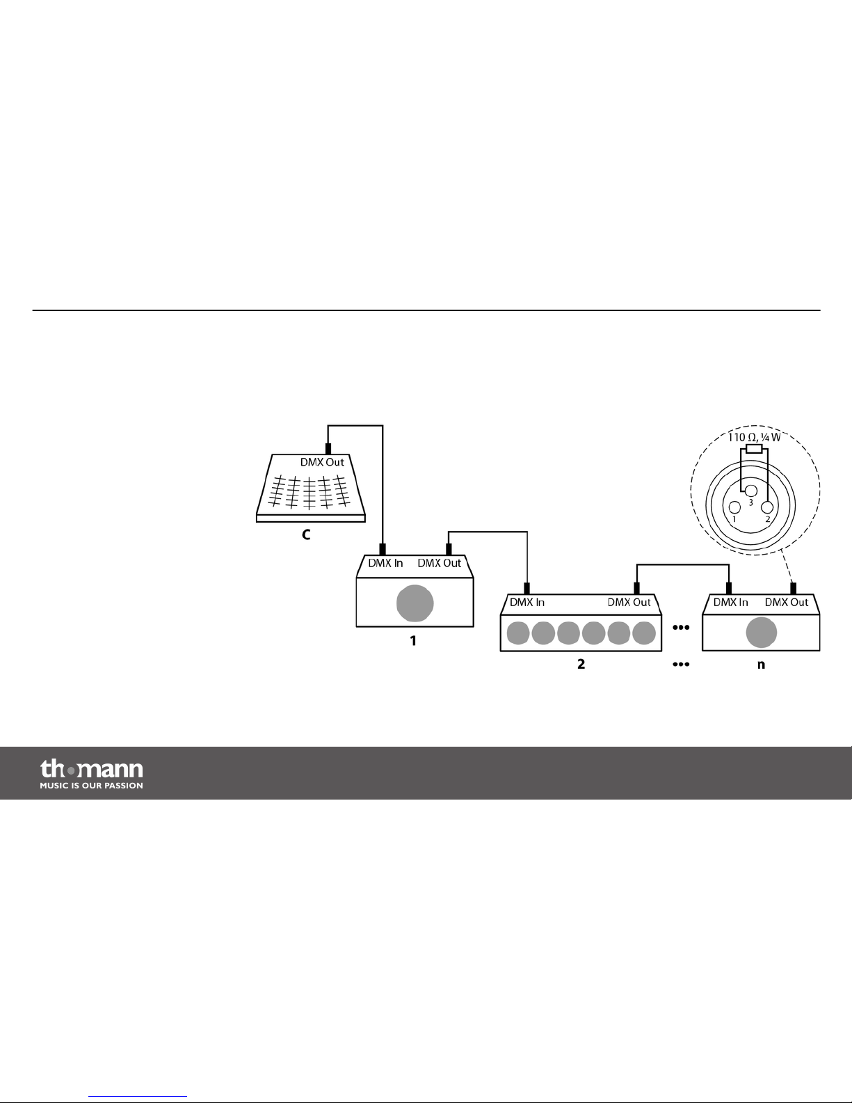
Connect the DMX output of the device (C) to the DMX input of the first DMX device (1). Con‐
nect the output of the first DMX device to the input of the second one, and so on to form a
daisy chain. Always ensure that the output of the last DMX device in the daisy chain is termi‐
nated with a resistor (110 Ω, ¼ W).
Connections in DMX mode
Installation
DMX controller
14
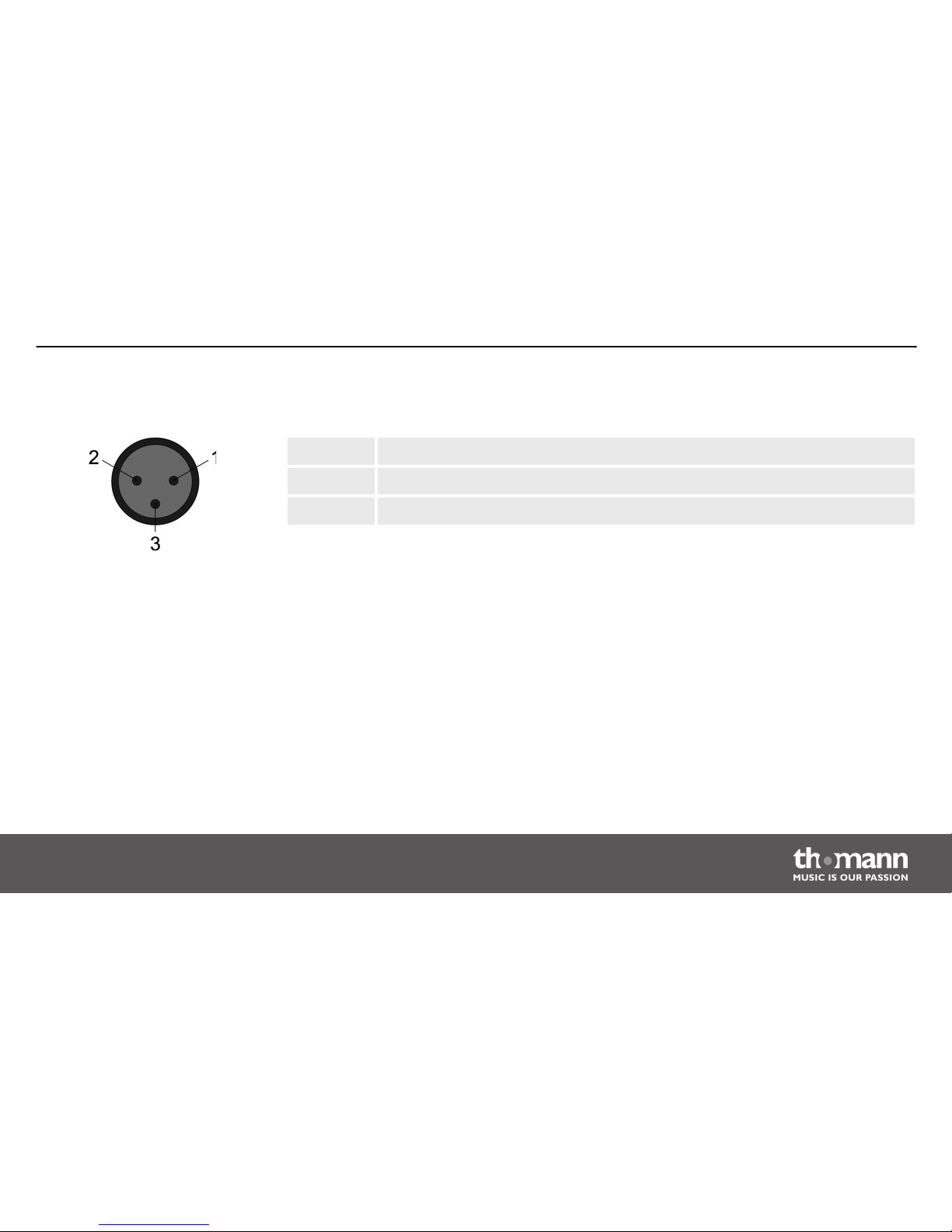
Two 3-pin XLR sockets serve as DMX outputs. The following drawing and table indicate the pin
assignment of the sockets.
1 Ground, shielding
2 DMX data (–)
3 DMX data (+)
For each function of a DMX device (such as colour, brightness, strobe interval, etc.), a separate
control channel is provided. The control channels can be assigned to a block of channel faders
of the Invader. For example, to assign the 10 channels of a device to the channel faders CH1 CH10 of the Invader, you have to set the DMX address of the device to be controlled to ‘1’. The
next channel fader CH11 of the Invader should then control the function of the first control
channel of another device in the DMX chain. On this device, then set the DMX address ‘11’.
Continue accordingly with further devices.
As a prerequisite for this manual control, fixture # 1 must be activated.
DMX outputs
DMX address and control chan‐
nels
Installation
DMX Invader 2420 MK2
15
The DMX address defines the number of the first DMX control channel of a device (1–
512).
Installation
DMX controller
16
5
Connections and operating elements
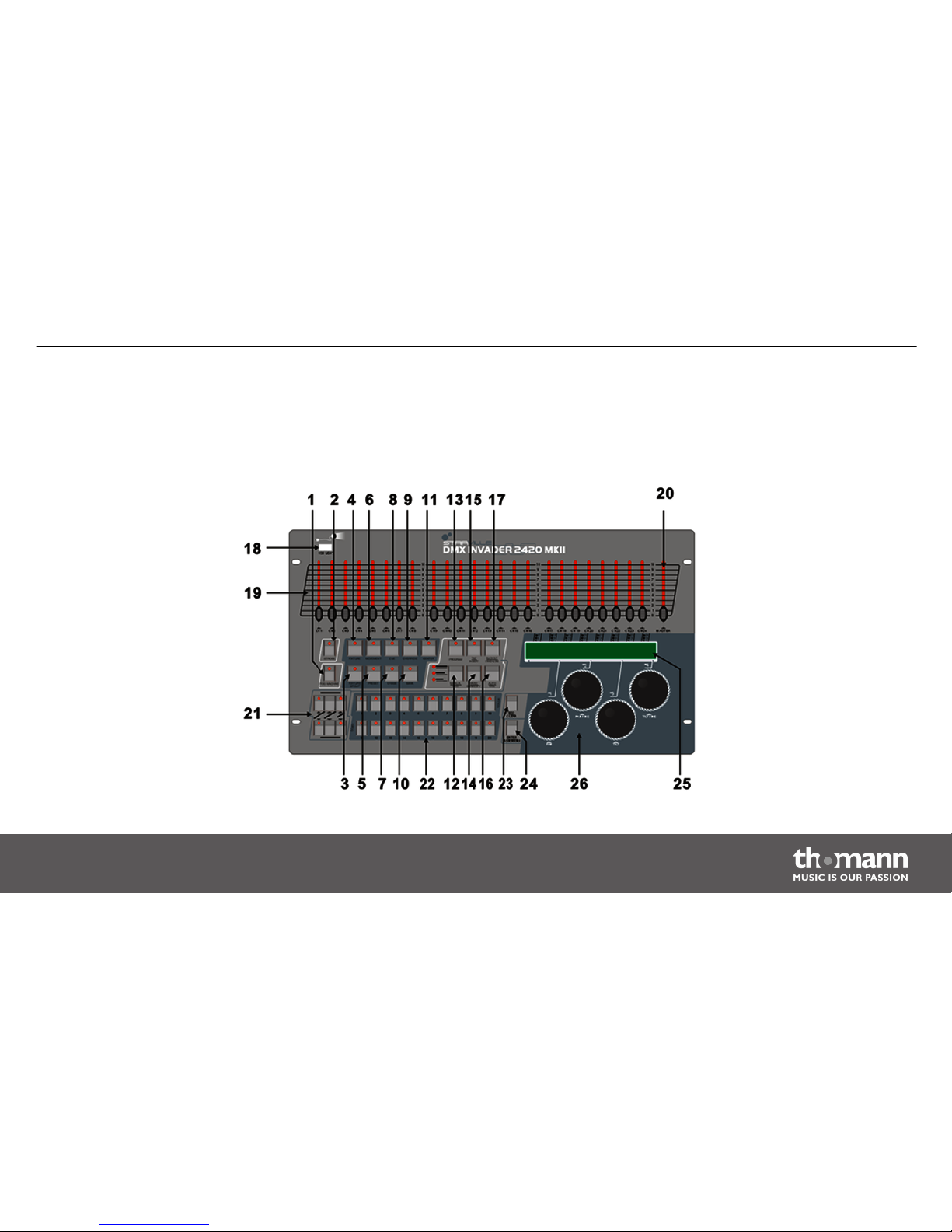
Front panel
Connections and operating elements
DMX Invader 2420 MK2
17
1 FOG MACHINE
Activates a connected fog machine (via DMX channel 481).
2 STROBE
Triggers a connected strobe (via DMX channels 483 & 484).
3 FIXTURE GROUP
Selects one or multiple fixture groups.
4 FIXTURE
If you assign the DMX address of the connected devices according to the channel list (Ä ‘Fixture number channel list’
on page 23) (the first device gets DMX address 1, the next one 25, the next one 49 and so on), you can press the [FIXTURE]
button and then use the number buttons [1 – 20] to address the individual devices directly. Their control channels are then
immediately assigned to the up to 24 channel faders.
5 PRESET
Button for subsequently selecting a colour or gobo preset using the number buttons [1 – 10] or [11 – 20] respectively.
Connections and operating elements
DMX controller
18
6 MOVEMENT
Button for subsequently selecting a programmed movement using the number buttons [1 – 10].
7 CHASE
Button for subsequently selecting a programmed Chase (sequence of several Scenes).
8 CUE
Button for subsequently selecting a programmed Cue (sequence of several Chases).
9 OVERRIDE
Button for subsequently selecting a programmed scene that overrides the running show.
10 BANK
Button for subsequently selecting a scene.
11 CENTER
If you have programmed Center positions for a device, and this device is used in the current scene, you can press this button
and then use the number buttons [1 – 20] to apply Center positions.
Connections and operating elements
DMX Invader 2420 MK2
19
12 MANUAL/REC
In function mode, this button activates the manual mode.
In programming mode, this button initiates the saving.
13 PROGRAM
Keep this button pressed for 2 seconds to enable or disable the programming mode.
14 MUSIC/BANK COPY
In function mode, this button activates the sound-controlled mode.
In programming mode, this button initiates copying.
15 TAP/INSERT
In function mode (automatic only), you can adjust the speed of certain procedures by pressing this button repeatedly.
In programming mode, you can use this button to insert programme elements.
16 AUTO/DEL
In function mode, this button activates the automatic mode.
In programming mode, you can use this button to delete programme elements.
Connections and operating elements
DMX controller
20
17 BLACKOUT/STAND ALONE
Press this button briefly in function mode to blackout all devices simultaneously.
Keep this button pushed for 2 seconds to enable stand alone operation, in which all DMX functions are disabled. Press this
button briefly to end stand alone operation - this activates the BLACK OUT function, which can be disabled by briefly
pressing this button once again.
18 USB Light
The USB port is used exclusively to connect a USB lamp.
19 Fader
Use these faders to adjust the DMX values for each channel.
20 MASTER
Controls the Dimmer channel of the selected device.
21 STAND ALONE
Controller elements for the 5-pin STANDALONE outputs.
22 Number buttons 1-20
+ function button Description
Connections and operating elements
DMX Invader 2420 MK2
21

Fixture To address up to 20 devices.
Fixture Group To set up and select up to 20 fixture groups.
Movement To select 10 programmed movements (buttons 1-10 only).
Preset To set up and select COLOR presets (buttons [1-10]) and GOBO presets (buttons [11-20]) on up
to 20 memory pages.
Cue To select and programme up to 60 Cues.
Chase To select and programme up to 60 Chases.
Override To select and programme up to 20 Overrides.
Bank To select and programme up to 1200 Scenes from 60 banks.
Center To select and programme up to 20 Center positions.
23 ESC/CLEAR
Back to the previous menu level, or to delete values in programming mode.
Connections and operating elements
DMX controller
22
24 ENTER/MAIN MENU
To access the main menu or confirm values.
25 LCD
Indicates the current device activity or programme status.
26 Jog wheels
With these encoders, you perform a lot of adjusting and selecting when operating of the device.
The following table shows you which DMX channels are assigned to the 24 channel
faders by pressing the number buttons [1 – 20] (the LED of the [FIXTURE] button must
light up at this!).
Fixture number channel list
Connections and operating elements
DMX Invader 2420 MK2
23
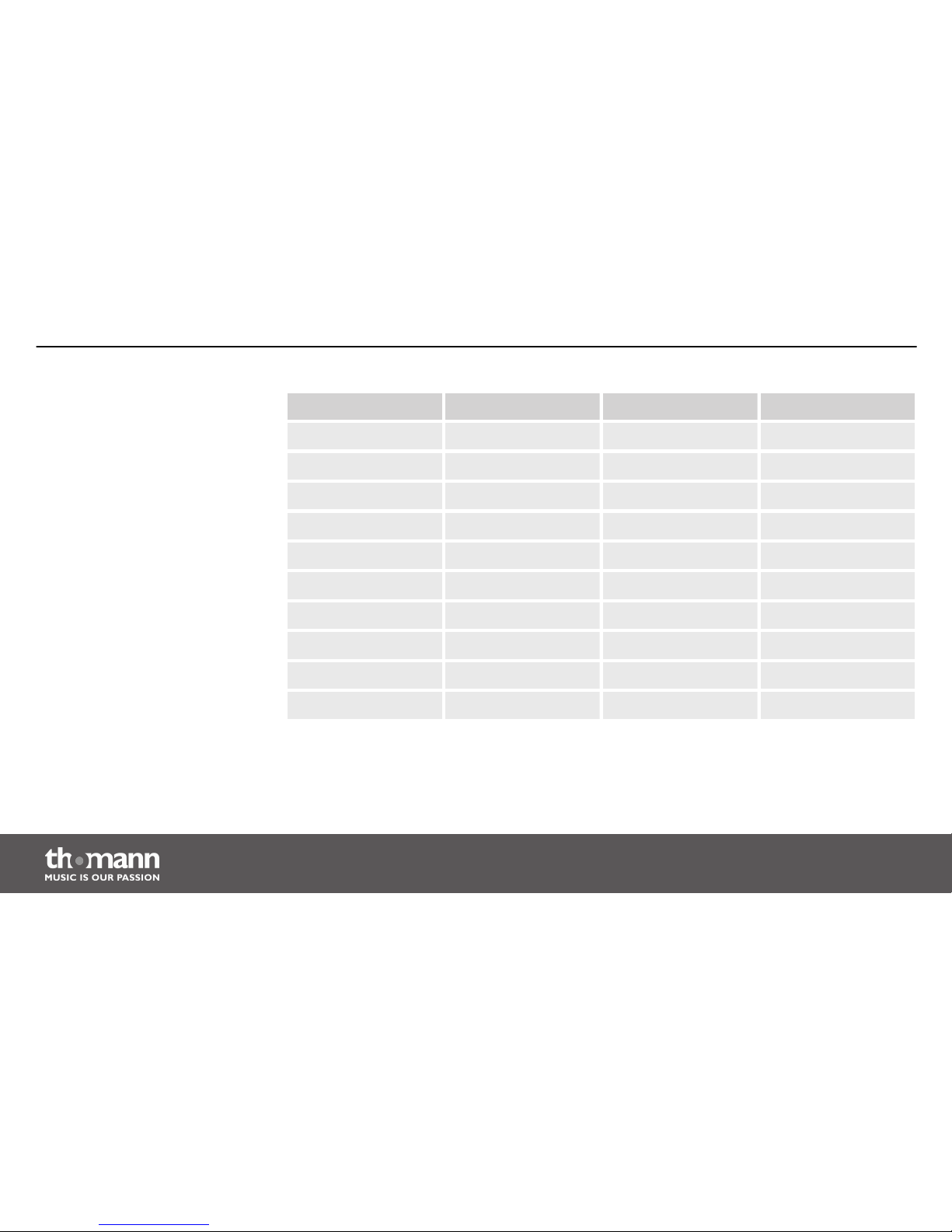
Number buttons DMX channels Number buttons DMX channels
1 1-24 11 241-264
2 25-48 12 265-288
3 49-72 13 289-312
4 73-96 14 313-336
5 97-120 15 337-360
6 121-144 16 361-384
7 145-168 17 385-408
8 169-192 18 409-432
9 193-216 19 432-456
10 217-240 20 457-480
Connections and operating elements
DMX controller
24
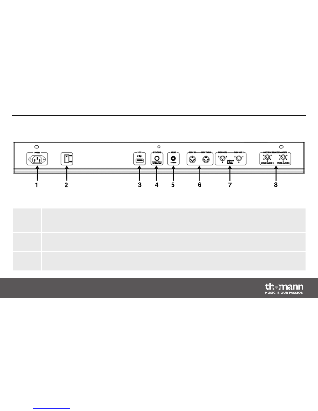
1 POWER
Connect the IEC chassis connector via the supplied power cord to an AC outlet that provides the voltage specified in
the Technical Data.
2 ON / OFF switch
Turns the unit on or off.
3 USB
USB port for software updates, data backup and importing saved banks.
Rear panel
Connections and operating elements
DMX Invader 2420 MK2
25
4 STROBE
To trigger analogue strobes, that can't make use of the DMX signal. Signal +12V .
5 AUDIO LINE IN
You can connect audio line signals (0,1 V ~ 1 V pp) to this RCA socket to be used for the sound-controlled mode. When
this switch socket is used, the built-in microphone is deactivated.
6 MIDI IN / MIDI THRU
Via the ‘MIDI IN’ socket, the device receives MIDI data. ‘MIDI THRU’ feeds the incoming MIDI data to the next MIDI
device.
7 DMX OUT
These two terminals send DMX signals to DMX capable devices. Use a cable with 3-pin XLR connectors to connect the
devices.
8 STAND ALONE
These ports are used only in master / slave mode. Use a cable with 5-pin XLR connector to 1/4" phone jack for the first
device, then the remote control of the first unit will also control the Stand by, Function and Mode function of all fur‐
ther devices.
Connections and operating elements
DMX controller
26
6
Operating
After switching the Invader on, the console automatically performs a self-test, its progress will
appear on the display. Once this is completed, the device can be used.
6.1
‘Setting’ menu
1. Enter the programming mode by holding down the [PROGRAM] button for 2 seconds.
The LED of the [PROGRAM] button flashes when the programming mode is activated.
Calling up the menu
Operating
DMX Invader 2420 MK2
27
2. Hold down the [ENTER / MAIN MENU] button for 2 seconds to enter the main menu.
The main menu allows to access the following 17 sub menus:
1. Create a new fixture profile
2. Modify a fixture profile
3. Delete a fixture profile
4. Patch a fixture
5. Reverse channel setup
6. Fade mode select
7. Blackout mode select
8. MIDI channel select
9. Chase run by inside/outside time
10. Auto remote address
Operating
DMX controller
28

11. Read U disk
12. Write U disk
13. Modify password
14. Enable password
15. Erase all memory
16. Audio input range adjust
17. Channel value display mode
Select the desired menu item with jog wheel # 1 and press the [ENTER / MAIN MENU] button to
enter the respective submenu for editing.
Press the [ESC / CLEAR] button to return to the previous menu level. Press repeatedly to finally
leave the menu.
Exiting the menu
Operating
DMX Invader 2420 MK2
29
Only after leaving the menu you can exit the programming mode. To do so, keep the
[PROGRAM] button pressed for 2 seconds.
6.1.1
Create a new fixture profile
If you create profiles for the used device, you can replace the fader channel number in
the display by the description for the actual function of the fader on the selected
device. This does not affect the functionality, but improves the clarity a lot.
Operating
DMX controller
30
 Loading...