


403 16" Trade Bandsaw
503 20" Trade Bandsaw
603 24" Trade Bandsaw
Original Instruction Manual
Important
For your safety read instructions carefully before
assembling or using this product.
Save this manual for future reference.
Always wear safety glasses when
using woodworking equipment.
Always read the instructions
provided before using
woodworking equipment.
i
Version 3.4
December 2017

2
Contents
1 Explanation of Symbols
2 General Health and Safety Guidance
3 Additional Health and Safety Guidance for Bandsaws
4 Features of the 403, 503 and 603 Bandsaws
5 Specifications
6 Dust Extraction
7 Installation and Operation
8 Operation and Bandsawing Practice
9 Maintenance
10 Troubleshooting
11 Parts Lists and Diagrams - 403/UK1 and 403/UK3
12 Parts Lists and Diagrams - 503/UK3
13 Parts Lists and Diagrams - 603/UK3
14 Electrical Connection and Wiring Diagrams
EU Declaration of Conformity

3
THE SYMBOLS AND THEIR MEANINGS SHOWN BELOW MAY BE USED THROUGHOUT THIS MANUAL. PLEASE ENSURE THAT YOU
TAKE THE APPROPRIATE ACTION WHEREVER THE WARNINGS ARE USED.
1. Explanation of Symbols
i
i
i
i
i
Mandatory
Instructions
Warning
Read and fully understand the instruction manual
before attempting to use the machine.
Indicates an instruction that requires particular attention
Wear protective eyewear
Use respiratory protective equipment
Use suitable protective footwear
Use hearing protection
Use protective work gloves
Indicates a risk of severe personal injury or
damage to the machine
Indicates a risk of severe personal injury
from electrical shock
Risk of personal injury from lifting of heavy items
Indicates a risk of severe personal injury from
airborne objects
Risk of fire
Kg
i

4
2. General Health and Safety Guidance
Ensure that you carefully read and fully understand the
instructions in this manual before assembly, installation and use
of this product. Keep these instructions in a safe place for future
reference.
WARNING: for your own safety, do not attempt to operate this machine
until it is completely assembled and installed according to these
instructions.
WARNING: When using any machine, basic safety precautions should
always be followed to reduce the risk of fire, electric shock and
personal injury.
Safe Operation
1. Use Personal Protective Equipment (PPE)
• The operation of any machine can result in foreign objects being thrown
into your eyes, which can result in severe eye damage. Protective eyewear
or other suitable eye protection or face shield should be used at all
times. Everyday spectacles only have impact resistant lenses. They are not
protective eyewear and do not give additional lateral protection.
• Use respiratory protective equipment (dust mask etc.) if the machining
operation creates dust. Exposure to high levels of dust created by
machining hardwoods, softwoods and man made composite boards can
result in serious health problems. Some imported hardwoods give off
highly irritating dust, which can cause a burning sensation. The use of
respiratory protective equipment should not be seen as an alternative to
controlling the risk of exposure at source by using adequate dust
extraction equipment.
• The use of ear plugs or ear defenders is recommended when the machine
is in use, particularly if the noise level exceeds 85 dB.
• Wear suitable protective gloves when handling cutting tools or blades.
Gloves should NOT be worn when using the machine as they can be
caught in moving parts of the machine.
• Non-slip safety footwear is recommended when using the machine and
handling large work pieces.
2. Dress appropriately
• Do not wear loose clothing, neckties or jewellery; they can be caught in
moving parts of the machine.
• Roll up long sleeves above the elbow.
• Wear protective hair covering to contain long hair.
3. Safety warnings
• Find and read any warning labels on the machine
• It is important that any labels bearing health and safety warnings are
not removed, defaced or covered. Replacement labels can be obtained by
contacting our Customer Service Department.
4. Familiarise yourself with the machine
• If you are not thoroughly familiar with the operation of this machine,
obtain advice from your supervisor, instructor, or other qualified person or
contact your retailer for information on training courses. Do not use this
machine until adequate training has been undertaken.
5. Take care when moving or positioning the machine
• Some machines can be very heavy. Ensure the floor of the area
in which the machine is to be used is capable of supporting
the machine.
• The machine and its various components can be heavy.
Always adopt a safe lifting technique and seek assistance when lifting
heavy components. In some cases it may be necessary to use mechanical
handling equipment to position the machine within the work area.
• Some machines have optional wheel kits available to allow them to be
manoeuvred around the workshop as required. Care should be taken to
install these according to the instructions provided.
• Due to the nature of the design of some machines the centre of gravity
will be high making them unstable when moved. Extreme care should be
taken when moving any machine.
• If transportation of the machine is required then all precautions relating
to the installation and handling of the machine apply. In addition, ensure
that any vehicles or manual handling equipment used for transportation
are of adequate specification.
6. The machine should be level and stable at all times
• When using a leg stand or cabinet base that is designed to be fitted to
the machine, always ensure that it is securely fastened to the machine
using the fixings provided.
• If the machine is suitable to be used on a workbench, ensure that the
workbench is well constructed and capable of withstanding the weight
of the machine. The machine should always be securely fastened to the
workbench with appropriate fixings.
• Where possible, floor standing machines should always be secured to the
floor with fixings appropriate to the structure of the floor.
• The floor surface should be sound and level. All of the feet of the
machine should make contact with the floor surface. If they do not, either
re-locate the machine to a more suitable position or use packing shims
between the feet and the floor surface to ensure the machine is stable.
7. Remove adjusting keys and wrenches
• Ensure that all adjusting wrenches and keys are removed before
switching the machine ‘ON’. There is a risk of severe personal injury or
damage to the machine from airborne objects.
8. Before switching the machine ‘ON’
• Clear the machine table of all objects (tools, scrap pieces etc.)
• Make sure there is no debris between the work piece and the
table / work support.
• Ensure that the work piece is not pressed against, or touching the saw
blade or cutting tool.
• Check all clamps, work holding devices and fences to ensure that they
are secure and cannot move during machining operations.
• Plan the way that you will hold and feed the work piece for the entire
machining operation.
9. Whilst machining
• Before starting work, watch the machine while it runs. If it makes
an unfamiliar noise or vibrates excessively, switch the machine ‘OFF’
immediately and disconnect it from the power supply. Do not restart until
finding and correcting the source of the problem.
10. Keep the work area clear
• Working clearances can be thought of as the distances between
machines and obstacles that allow safe operation of every machine
without limitation. Consider existing and anticipated machine needs, size
of material to be processed through each machine and space for auxiliary
stands and/or work tables. Also consider the relative position of each
machine to one another for efficient material handling. Be sure to allow
yourself sufficient room to safely operate your machines in any
foreseeable operation.
• Cluttered work areas and benches create the risk of accidents. Keep
benches clear and tidy away tools that are not in use.
• Ensure that the floor area is kept clean and clear of any dust and debris
that may create trip or slip hazards.
11. Consider the work area environment
• Do not expose the machine to rain or damp conditions.
• Keep the work area well lit and ensure that there is artificial lighting
available when there is insufficient natural light to effectively light the
work area. Lighting should be bright enough to eliminate shadow and
prevent eye strain.
• Do not use the machine in explosive environments eg. in the presence of
flammable liquids, gases or dust.
• The presence of high levels of dust created by machining wood can
present a risk of fire or explosion. Always use dust extraction equipment
to minimise the risk.
12. Keep other persons away (and pets)
• The machine is designed to be used by one person only.
• Do not let persons, especially children, touch the machine or extension
cable (if used) and keep visitors away from the work area.
• Never leave the machine running unattended. Turn the power supply off
and do not leave the machine unattended until it comes to a

5
2. General Health and Safety Guidance
complete stop.
• If the work area is to be left unattended, all machinery should be
switched ‘OFF’ and isolated from the mains power supply.
13. Store machines safely when not in use
• When not in use, machines should be stored in a dry place, out of reach
of children. Do not allow persons unfamiliar with these instructions or
with the machine to operate it.
14. Do not overreach
• Choose a working position that allows your body to remain balanced and
feed the work piece in to the machine without overreaching.
• Keep proper footing and balance at all times.
15. Electrical supply
• Electrical circuits should be dedicated to each machine or large enough to
handle combined motor amp loads. Power outlets should be located near
each machine so that power or extension cables are not obstructing hightraffic areas. Observe local electrical guidelines for proper installation of
new lighting, power outlets, or circuits.
• The machine must be connected to an earthed power supply.
• The power supply must be equipped with a circuit breaker that provides
short circuit, overload and earth leakage protection.
• The voltage of the machine must correspond to the voltage of the mains
power supply.
• The mains plug fitted to the machine should always match the power
outlet. Do not modify the plug in any way. If a replacement plug is
required it should be fitted by a competent person and of the correct type
and rating for the machine.
• If you are unsure about any electrical connections always consult a
qualified electrician.
16. Avoid unintentional starting of the machine
• Most machines are fitted with a no-volt release (NVR) switch to prevent
unintentional starting. If in doubt always ensure the machine switch
is in the ‘OFF’ position before connecting it to the power supply. This
means the machine will not automatically start up after a power cut or
switching on of the power supply, unless you first reset the start switch.
17. Outdoor use
• Your machine should not be used outdoors.
18. Extension cables
• Whenever possible, the use of extension cables is not recommended.
If the use of an extension cable is unavoidable, then it should have a
minimum core cross section of 2.5 mm² and limited to a maximum length
of 3 metres.
• Extension cables should be routed away from the direct working area to
prevent a trip hazard.
19. Guard against electric shock
• Avoid body contact with earthed or grounded surfaces such as pipes
and radiators. There is an increased risk of electric shock if your body is
earthed or grounded.
20. Always work within the machine’s intended capacities
• Operator safety and machine performance are seriously adversely
affected if attempts to make the machine perform beyond its limits are
made.
21. Do not abuse the power cable
• Never pull the power cable to disconnect it from the power socket.
Always use the plug.
• Keep the power cable away from heat, oil and sharp edges.
• Do not use the power cable for carrying or moving the machine.
22. Secure the work piece
• Ensure that the work piece is securely held before starting to machine it.
• When working within 300 mm of the machining area, always use a push
stick to feed the work piece in to the blade or cutting tool. The push stick
should have a minimum length of 400 mm. If the push stick becomes
damaged, replace it immediately.
• Use extra supports (roller support stands etc.) for any work pieces large
enough to tip when not held down to the table top.
• Do not use another person as a substitute for a table extension, or as
additional support for a work piece that is longer or wider than the basic
table, or to help feed, support, or pull the work piece.
• Do not attempt to machine more than one work piece at a time.
• When feeding the work piece towards the blade or cutting tool never
position your hands in direct line of the cutting path. Avoid awkward
operations and hand positions where a sudden slip could cause your
hand or fingers to move into the machining area.
23. Stay alert
• Safety is a combination of operator common sense and alertness at all
times when the machine is being used.
• Use all machines with extreme care and do not use the machine when
you are tired or under the influence of drugs, alcohol or medication.
24. Use the correct tool for the job
• Do not use the machine for any purpose other than which it
was designed.
• When selecting replacement cutting tools and blades, always ensure that
they are designed to cut the material that you intend to use them for. If
in any doubt seek further advice from the manufacturer.
25. Connect dust extraction equipment
• Always use dust extraction equipment. The dust extractor should be of
suitable size and capacity for the machine that it is connected to and
have a filtration level appropriate to the type of waste being collected.
Refer to the relevant section of the manual for details of the specific dust
extraction requirements for this machine.
• The dust extractor should be switched ‘ON’ before starting the machine
that it is connected to. The dust extractor should be left running for 30
seconds after the last machining operation is complete in order to clear
any residual waste from the machine.
26. Ensure that the machine is correctly guarded
• Never use the machine if any of the standard safety guards and
equipment are removed or damaged.
• Some machines incorporate safety interlocks to prevent the machine
from being used without the guards in place. Never attempt to bypass or
modify the interlocks to allow the machine to be used without the guards
in place.
27. Maintain your machine with care
• This manual gives clear instructions on installation, set up and
operation of the machine and also details any routine and preventative
maintenance that should be performed periodically by the user.
• Remember always to switch off and unplug the machine from the power
supply before carrying out any setting up or maintenance operations.
• Follow any instructions for the maintenance of accessories
and consumables.
• Do not use compressed air to clean the machine. Always use a brush to
dislodge dust in places that are awkward to reach and a dust extractor to
collect the waste.
• Inspect electric cables periodically and, if damaged, have them replaced
by an authorised service facility or qualified electrician.
• Inspect extension cables (if used) periodically and replace if damaged.
28. Keep cutting tools sharp and clean
• Correctly maintained cutting tools are easier to control and less likely
to bind.
• Cutting tools and blades can become hot during use. Take extreme care
when handling them and always allow them to cool before changing,
adjusting or sharpening them.
29. Disconnect the machine from the power supply
• When not in use, before servicing, changing blades etc. always disconnect
the machine from the power supply.
30. Check for damaged parts
• Before each use of the machine, it should be carefully checked to
determine that it will operate properly and perform its
intended function.
• Check for alignment of moving parts, binding of moving parts, breakage

6
2. General Health and Safety Guidance
of parts and any other conditions that may affect the operation of
the machine.
• A guard or other part that is damaged should be properly repaired
or replaced by a qualified person unless otherwise indicated in this
instruction manual.
• Do not use the machine if the switch does not turn the machine ‘ON’
and ‘OFF’.
• Have defective switches replaced by a qualified person.
31. Warning!
• The use of any accessory or attachment, other than those recommended
in this instruction manual, or recommended by our Company may present
a risk of personal injury or damage to the machine and invalidation of
the warranty.
32. Have your machine repaired by a qualified person
• This machine complies with the relevant safety rules and standards
appropriate to its type when used in accordance with these instructions
and with all of the standard safety guards and equipment in place. Only
qualified persons using original spare parts should carry out repairs.
Failure to do this may result in considerable danger to the user and
invalidation of warranty.
33. Caution! Motor may become hot during use
• It is normal for motors on some machines to become hot to the touch
during use. Avoid touching the motor directly when in use.
Safe Operation
1. Familiarise yourself with the machine
• Machining operations using bandsaws have a history of serious accidents.
Most result from contact with the moving blade while presenting material
to the blade or moving it from the table. Other minor accidents can occur
whilst setting, cleaning, adjusting or maintaining the machine.
• The machine is designed for cutting wood and composite board (plywood,
MDF etc.). Certain plastics can also be cut using a suitable blade.
2. Before switching the machine ‘ON’
• Ensure that the blade is correctly tensioned and aligned on the
bandwheels and the blade guides are correctly adjusted.
• Ensure that the teeth of the blade are pointing downwards.
• Check the condition of the blade to ensure that no teeth are missing,
damaged or deformed and the blade is not cracked or split. If any of
these conditions apply, replace the blade immediately.
• Ensure that the saw blade type and width are suitable for the material to
be cut.
• Check that the blade width is within the minimum and maximum
permitted on the machine and that the thickness of the blade is suitable
for the diameter of the wheel.
• Some machines have more than one cutting speed. For most wood
cutting applications the faster of the speeds should be used.
• Check the condition of the table insert. Replace it immediately if it is
damaged or showing signs of wear.
• Adjust the guard as close as possible to the work piece being cut.
• Check that access doors are fully closed and that the latches are secure.
3. Whilst machining
• Never apply sideways pressure to the blade as this may cause the blade
to break.
• Care must be taken when cutting wood with knots, nails or cracks in
it and / or dirt on it, as these can cause the blade to get stuck. If this
happens, switch the machine ‘OFF’ immediately and follow the procedure
detailed in the manual to remove the blade from the work piece.
• If cutting cylindrical timber use a suitable jig to prevent twisting of the
work piece.
4. This machine falls under the scope of the ‘Health and Safety at Work
etc. Act 1974’, and the ‘Provision and Use of Work Equipment Regulations
1998’. In addition the elimination or control of risks from wood dust is
included in the above regulations and the ‘Control of Substances Hazardous
to Health (COSHH) Regulations 2002’. We recommend that you study and
follow these regulations.
Further guidance can be found in the ‘Safety in the use of narrow bandsaws
– Woodworking sheet No.31’ and the ‘Safe use of woodworking machinery’
code of practice booklet (L114) published by Health and Safety Executive
and available from their website www.hse.gov.uk.
3. Additional Health and Safety Guidance for Bandsaws
7
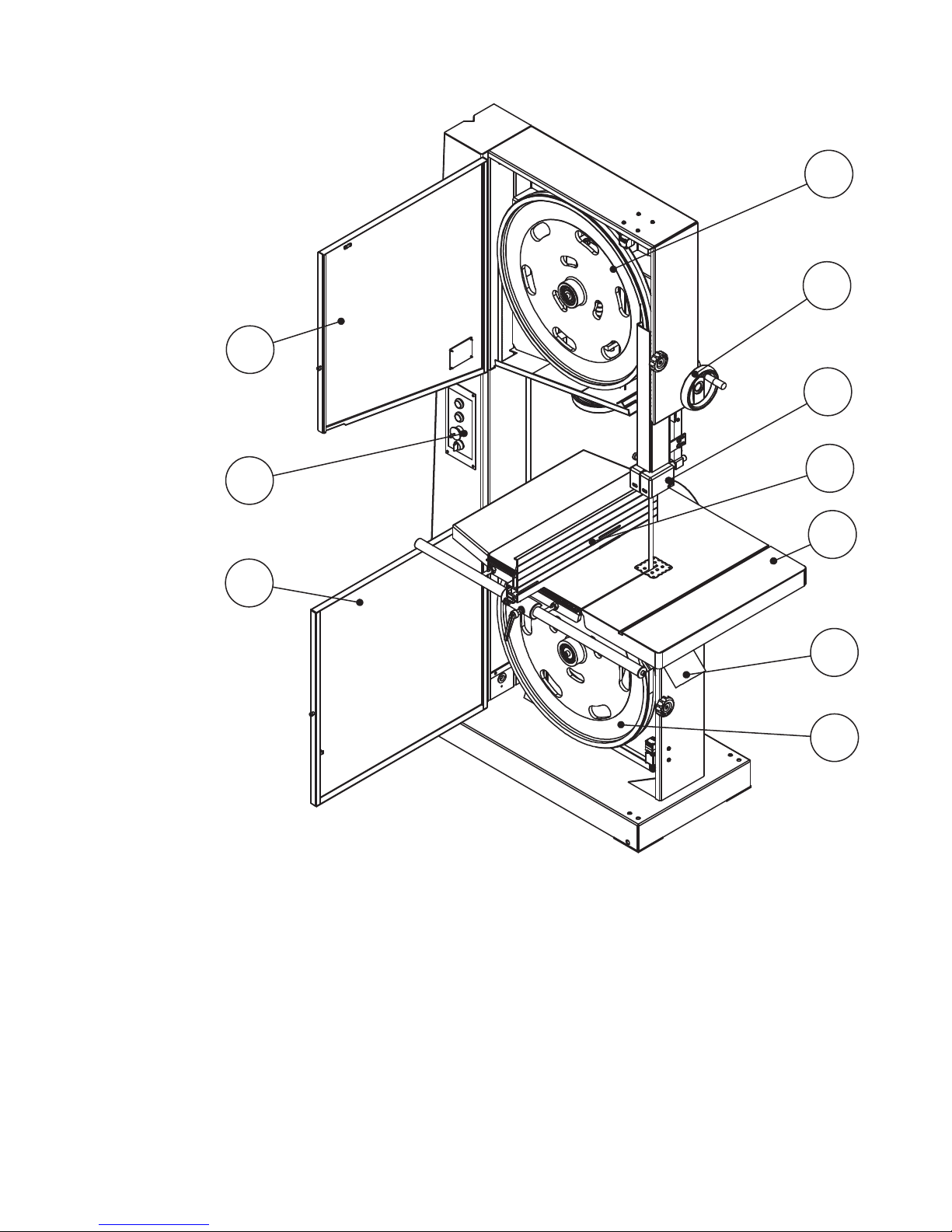
4. Features of the 403, 503 and 603 Bandsaws
1 Upper wheel
2 Upper guide lifting handwheel
3 Upper guide
4 Rip fence assembly
5 Table
6 Dust port
7 Lower wheel
8 Lower door
9 Switch with electric brake
10 Upper door
2
3
4
5
6
7
8
9
10
1
Model 403/UK1 403/UK3 503/UK3 603/UK3
Motor voltage 230 V / 50 Hz 400 V / 50 Hz 400 V / 50 Hz 400 V / 50 Hz
Current 9 A 4.8 A 7 A 8.2 A
Motor power output 1.5 kW 2.2 kW 3 kW 4 kW
Blade length 3531 mm 3531 mm 3962mm 4470 mm
Blade width 6 - 30 mm 6 - 30 mm 6 - 30 mm 10 - 35 mm
Max. cut depth 280 mm 280 mm 335 mm 370 mm
Throat width 390 mm 390 mm 480 mm 580 mm
Blade speed 1100 m/min 1100 m/min 1500 m/min 1500 m/min
Table size 578 x 420 mm 578 x 420 mm 633 x 485 mm 700 x 608 mm
Table tilt 0 - 45° 0 - 45° 0 - 45° 0 - 22.5º
Dust port diameter 100 mm 100 mm 100 mm 100 mm
Weight 166 kg 166 kg 227 kg 342 kg
5. Specifications
No Load Load
Sound Pressure Level < 80 dB(A) < 90 dB(A)
Sound Power Level < 90 dB(A) < 100 dB(A)

8
6. Dust Extraction
The Importance of Dust Extraction
Suitable dust extraction is essential to avoid the possibility of serious health
problems related to wood dust. It is also necessary in order to ensure the
waste producing machine performs safely and effectively. Some woods are
extremely toxic and in addition to suitable dust extraction machines it is
recommended that PPE such as respirators are also used.
Record Power Dust Extraction Machines
Below is a summary of the Record Power range. Please visit your local
stockist or go online for full details.
DX1000 Fine Filter 45 Litre Extractor
45 litre capacity, 1 kW motor, 0.5 micron filtration. Includes hose.
RSDE1 Fine Filter 45 Litre Extractor
45 litre capacity, 1 kW motor, 0.5 micron filtration. Includes hose.
RSDE/2 Fine Filter 50 Litre Extractor with Accessories
50 litre capacity, 1 kW motor, 0.5 micron filtration, includes wheel kit, hose
cuff power tool adaptor hose and spare filter bags. Includes hose.
RSDE/2A Fine Filter Auto-Switching 50 Litre Extractor with
Accessories
50 litre capacity, 1 kW motor, 0.5 micron filtration, includes wheel kit, hose
cuff power tool adaptor hose and spare filter bags. Includes hose.
DX4000 Fine Filter Twin Motor 80 Litre Extractor
80 litre capacity, 2 x 1 kW motors, 0.5 micron filtration. Includes hose.
DX5000 Fine Filter Twin Motor 200 Litre Extractor
200 litre capacity, 2 x 1 kW motors, 0.5 micron filtration. Includes hose.
CGV286 CamVac Series Compact Extractor
36 litre capacity, 1 kW motor single or twin, 0.5 micron filtration.
CGV286-WALL CamVac Series Wall Mounted Extractor
150 litre capacity, 1 kW motor single or twin, 0.5 micron filtration.
CGV336 CamVac Series Medium Extractor
55 litre capacity, 1 kW motor single or twin, 0.5 micron filtration.
CGV386 CamVac Series Large Extractor
90 litre capacity, 1 kW motor twin or triple, 0.5 micron filtration.
CGV486 CamVac Series Heavy Duty Extractor
200 litre capacity, 1 kW triple motor, 0.5 micron filtration.
CX2000 Compact Chip Collector
54 litre capacity, 0.56 kW motor. Includes hose.
CX2500 80 Litre Chip Collector
80 litre capacity, 0.55 kW motor. Includes hose.
CX3000 Heavy Duty Chip Collector
128 litre capacity, 0.56 kW motor. Includes hose.
AC400 2 Stage Air filter with Remote, 3 speeds and Time Delay
Collects airborne dust, 1 micron filtration.
Bandsaws Table Saws
Planer
Thicknessers
Dust
Extraction
SystemsLathes
Sanding
Machines
Airborne Dust
Collection
DX1000
RSDE1
RSDE/2
RSDE/2A
DX4000
DX5000
CGV286
CGV286-WALL
CGV336
CGV386
CGV486
CX2000
CX2500
CX3000
AC400
Recommended for heavy use
Recommended for light / intermittent use
Can be used

9
6. Dust Extraction
All bandsaws should be used only with suitable dust extraction equipment
connected.
The minimum advisable air speed is 20 m/s for wood with a humidity of less
than 12%. For wood with greater humidity it is advisable to increase the air
speed to 25-28 m/s.
Capacity: Approximately 600 m3/h.
Pressure drop at each dust extraction connection outlet at the conveying air
velocity: 530 Pa.
7. Installation and Operation
Installation Zone Characteristics
It is prohibited to install the machine in explosive environments.
The installation zone must be selected evaluating the work space required
depending on the dimension of the pieces to be machined,and taking
into account that a free space of at least 800 mm must be left around the
machine.It is also necessary to check The floor capacity and its surface, so
that the machine base is evenly resting on its four supports.A power outlet
and a chip-suction system connection shall be closeto the selected machine
setting and it must be conveniently lighted.
Lifting
The machine can be lifted using a fork-lift truck, placing the forks under the
feet or by using a “SLING”, as shown in Fig 7.1, with a lifting capability of
2000 Kg.
Positioning The Machine
For correct and rational organisation of the work area:
• Install the machine in an area that will not amplify vibration or noise
• Verify that the work area is adequately illuminated.
• When placed between other machinery there should be a space of at least
80 cm. It is necessary to anticipate sufficient space for cutting long work
pieces traversly and for the fitting of rollers or other types of support,in
front and at the rear of the table.
There are four holes for fixing the machine to the floor. When fixing to the
floor it is recommended not to over tighten the fixtures to avoid increasing
vibration.It is also advisable to place anti-vibration materials between the
floor and the feet of the machine.
Sling 2000 kg
Timber
Fig 7.1
WARNING
10
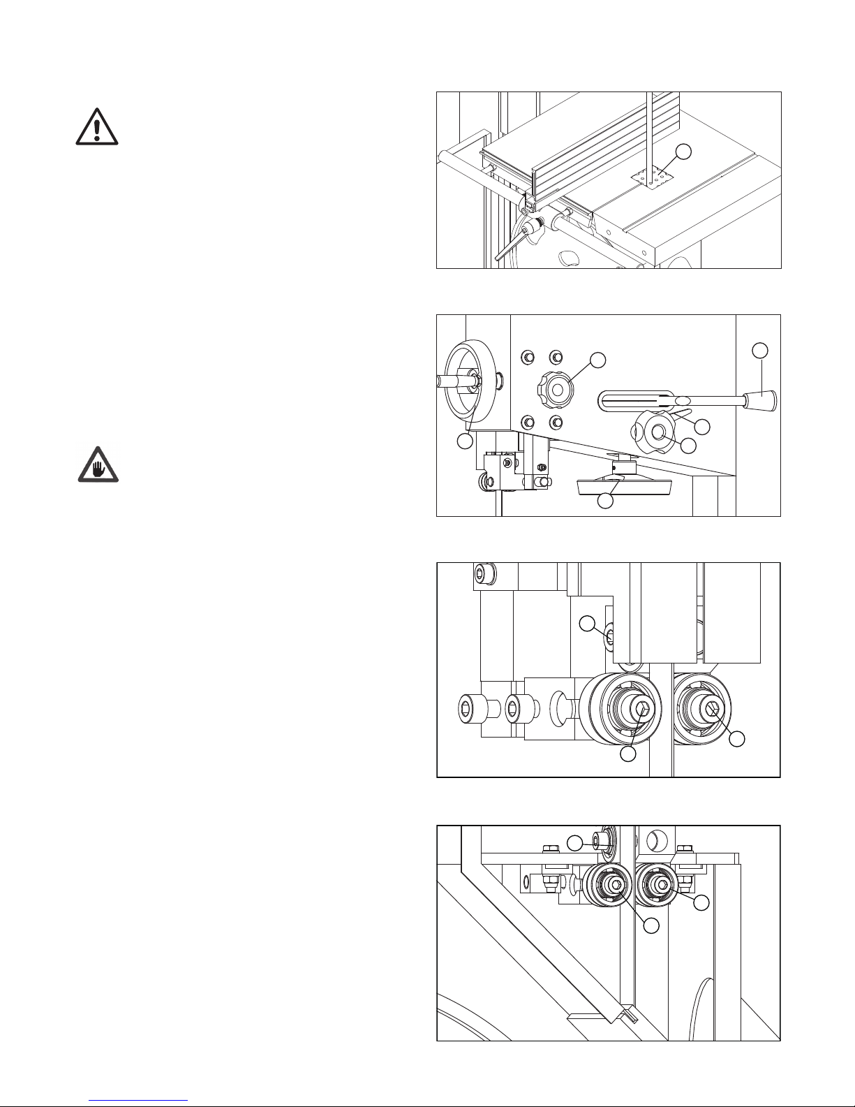
Fig 7.2
A
Blade Mounting and Adjustment
Before fitting the blade ensure that the machine is unplugged
from the power supply. Turn the brake off to allow manual
movement of the band wheels.
To mount the blade first remove the table insert (Fig 7.2, A) Place the
blade onto the bandwheel checking the teeth are in a correct position, and
then tighten the tension using the handwheel (Fig 7.3, A). The correct
tension value is indicated on the tension scale inside the upper door, the
indicated value corresponds to the width of the blade.
Turn the bandwheels manually, checking that the blade does not interfere
with any fixed parts and that the blade is placed correctly on the
bandwheels. The points of the teeth should slightly protrude over the edge
of the bandwheels. To adjust the blade position on the bandwheels slacken
the locking lever (Fig 7.3, B), and then turn the knob (Fig 7.3, C): the
blade will move inwards when turn the knob clockwise and the blade will
move further out when turn the knob anticlockwise; A quarter of one circle
is sufficient to make a noticeable displacement. Tighten the locking lever
after the blade is positioned correctly.
Reinstall the table insert, close the band wheels accessing doors.
After use we recommend slackening the blade tension, and to display a
visible sign on the machine advising of this procedure.
Remeber to check and re-tension before use. This operation prevents
damage to the bandwheel tyres.
Setting the Blade Guard and Guides
Adjusting the Saw Blade Guard
The adjustable saw band guard should be positioned as close as possible to
the work piece. To adjust the height, release the locking knob (Fig 7.3, D)
and turn the hand wheel (Fig 7.3, E) to move the guard up or down. Lock
the knob once the correct guard position is obtained. This operation must
always be carried out when the machine has stopped.
Roller Bearings Blade Guide
The roller bearings should be positioned as close to the blade as possible
but without touching it, to help maintain the correct cutting direction
during use. The positioning of these bearings is controlled by screw A of Fig
7.4. Once they have been adjusted, tighten screw A. They should be 2 mm
behind the teeth of the blade. The rear bearing prevents excessive backward
movement of the blade during operation and should be 1 - 2 mm from the
back of the blade. This can be adjusted using screw B of Fig 7.4.
Lower Saw Blade Guide
The roller bearings should be positioned as close to the blade as possible
but without touching it, to help maintain the correct cutting direction during
use. The positioning of these rollers is controlled by screw A of Fig 7.5.
Once adjusted, tighten screw A. They should be 2 mm behind the teeth of
the blade. The thrust shaft prevents excessive backwards movement of the
blade during operation and should be 1 - 2 mm from the back of the blade.
This can be adjusted using screw B of Fig 7.5.
CAUTION
Fig 7.3
A
B
C
D
E
F
Fig 7.5
Fig.4.4.1
A
Fig.4.4.2
A
B
C
Fig.4.5.1
D
E
A
A
B
A
A
B
F
Fig 7.4
Fig.4.4.1
A
Fig.4.4.2
A
B
C
D
E
A
A
B
F
7. Installation and Operation

11
Fig 7.6
A
B
C
D
Tilting The Work Table of the 403 and 503
The table may be set at 90º to the blade by adjusting the table stop screw
beneath the table. The table stop screw rests on the top of the lower
wheel bandwheel housing. By first slackening the locking nut A of Fig 7.6
and then adjusting the screw B of Fig 7.6, the table can be set correctly.
Retighten the locking nut A making sure that the setting is maintained.
To make adjustments of table tilting, slackening the locking handle D of Fig
7.6 and rotate the shaft C of Fig 7.6 with the special handle found in the
loose parts bag supplied with the machine. When adjustment is complete,
tighten the handle D of Fig 7.6 to lock it.
Tilting the Work Table of the 603
The table may be set at 90º to the blade by adjusting the table stop screw
beneath the table. The table stop screw rests on the top of the lower
wheel bandwheel housing. By first slackening the locking nut A of Fig 7.7
and then adjusting the screw B of Fig 7.7, the table can be set correctly.
Retighten the locking nut A making sure that the setting is maintained.
To make adjustments of table tilting, slackening bolt C of Fig 7.7. When
adjustment is correctly finished, tighten the handle D of Fig 7.7 to lock it.
Operating the Bandsaw
Before attempting to start the bandsaw ensure the emergency stop switch
is not in the depressed position. If necessary, unlock the switch with the key.
Ensure the brake switch is in the ON position as shown in Fig 7.8 then
press the on button.
To stop the bandsaw press either the off button or the emergency stop
button.
If the bandsaw is stopped using the emergency stop button the key must be
used to unlock it from the depressed position.
Prevention of Unauthorised Use
To prevent the bandsaw being used without authorisation, depress the
emergency stop button and remove the key.
On button
Off button
Emergency stop button
Brake switch
Fig 7.7
Fig 7.8
C
B
A
7. Installation and Operation

12
8. Operation and Bandsawing Practice
Basic Bandsawing Principles
• The blade cuts on a continuous down stroke.
• Slowly feed the workpiece towards the blade, using only light pressure
whilst letting the blade do the cutting. Always use a push stick and
take care.
• Firmly hold the workpiece and feed it towards the blade slowly, using the
push stick and keeping your hands well away from the blade.
• For best results the blade must be sharp. Damaged or worn blades should
always be replaced.
• Select the correct blade for the job, depending on the thickness of the
wood and the cut to be made (see blade selection).
• For straight cutting use the rip fence supplied.
• When cutting shapes, follow the design marked out by pushing and
turning the workpiece evenly. Do not attempt to turn the workpiece
without pushing it, as this may cause the workpiece to get stuck, or the
blade to bend.
CAUTION! Particular care should be taken towards the end of the cut
as there will be a sudden decrease in resistance and care must be taken
to stop hands from being thrown towards the blade. Always use a push
stick.
Always ensure that your machine is properly maintained and clean. Before
commencing work on an important project, it is advisable to familiarise
yourself with the operation of the equipment by practising on low value or
scrap materials.
Complicated Cutting
Very complicated cuts and small radius curves are the best accomplished
with the aid of pre-drilled holes combined with a few tangential or radial
cuts. This technique will achieve excellent results without putting undue
tension on the blade and blade guide assembly.
WARNING! In circumstances such as cutting deep or wet timber, the
work piece may close up behind the blade causing it to stall. In the
event that the blade stalls whilst cutting, ease the work piece backwards
slightly, to release feed pressure from the blade. Allow the blade to reach
full speed before continuing to feed the work piece in to the blade. If the
blade fails to move when feed pressure is released, immediately switch
off the machine and disconnect the power supply before attempting to
free the blade from the work piece.
WARNING! If any component of the machine fails whilst in use or if the
blade should break whilst the machine is running, immediately switch off
the machine and disconnect from the power supply. Remove the faulty
component and replace only with genuine Record Power replacement
parts. Any electrical components should only be replaced by a suitably
qualified person. To replace a broken blade, please refer to the section
of this manual entitled “Band saw Blade Set Up”. Always remember to
fully release the blade tension mechanism before attempting to fit a new
blade. If you are in any doubt about using the machine following a failure
or if you need to order replacement spare parts or blades, please contact
customer services in your country.
Restarting
In the Event of a Blockage or if the Machine Stalls
If the bandsaw stalls due to the blade becoming trapped in the work piece,
switch it off immediately by pressing the emergency stop button and wait
for the machine to come to a complete stop before proceeding further.
If the blade is trapped within the work piece, it may be necessary to prize
the work piece apart slightly using a suitable lever in order to free the
blade. If it is not possible to free the blade using this method, then it may
be necessary to cut the blade using suitable side cutters or tin snips.
Replace the blade if necessary and ensure that it is correctly tracked and
tensioned and that both doors of the bandsaw are fully closed and secured
before attempting to re-start the machine.
To re-start the machine, press the green button marked ‘I’ on the switch.
In the Event of a Power Failure
The bandsaw is fitted with a no volt release (NVR) switch to protect the
user against automatic starting of the machine when power is restored after
a power failure.
In the event of a power failure, first locate and rectify the source of the
failure. If the fault is within the power circuit of the workshop, there may be
an underlying cause (circuit overload etc.) that should be investigated by a
qualified electrician, before attempting to restore the power source.
If a cutting operation was taking place when the power supply was
interrupted, then it may be necessary to free the blade from the work piece
before attempting to re-start the machine.
Once the power is restored, the machine can be re-started by pressing the
green button marked ‘I’ on the switch.
Blade Selection (TPI)
The selection of the best blade configuration (see the table below) is
necessary for optimum cutting performance.
• Correct blade choice is primarily dependant on two factors: material
thickness and material type.
• Greater TPI should be selected as material thickness decreases.
• However, if the TPI is too great, the tooth loading will be insufficient to
enable penetration; and cutting. The teeth will also rapidly lose
their sharpness.
• For thicker material a lower TPI should be used otherwise the gullet will
not be sufficient to clear the waste and the blade will stall or burn
the wood.
• In general a minimum of 3 teeth should be in contact with the wood at
all times during cutting.
The accompanying blade selection chart (see the table below) gives
guidance on the TPI that should give the best results when cutting a variety
of material types and thickness. The table below provides recommendations
on selecting the correct blade for a variety of commonly used materials. If
in doubt about any aspects of blade selection contact Customer Services in
your country.
The table provides a guide to selection only. Exact tooth configurations
are not always available, nor are all blade configurations covered, but the
principles remain the same.
For special applications, custom blades can be supplied please call Customer
Services in your country and we can advise you accordingly on your specific
needs.

13
8. Operation and Bandsawing Practice
Material Material Thickness
<6 mm 6-12 mm 12-25 mm >25mm
Perspex 16 TPI 14 TPI - -
Chipboard - 6 TPI 3-6 TPI 3-4 TPI
Fibre board 16 TPI 14 TPI - -
Hardboard 10 TPI - - -
Plywood 10 TPI 8 TPI 6 TPI 3-4 TPI
Strawboard 14 TPI 10 TPI - -
Cork 14 TPI 6 TPI 3 TPI 3-4 TPI
Leather 14 TPI - - -
Rubber 10 TPI 8 TPI - -
Wood -log - - - 3-4 TPI
Wood -soft 6 TPI 3-6 TPI 3-4 TPI 3-4 TPI
Wood -hard 6 TPI 3-6 TPI 3-4 TPI 3-4 TPI
Wood -wet - - - 3-4 TPI
Blade Selection (TPI) - Cont.
Having selected an appropriate blade for the particular thickness and type
of material to be sawn, it is essential that the saw blade is allowed to cut
freely by not applying too much pressure.
• The need for excessive pressure is likely to be a result of the incorrect
blade selection or a worn blade and will result in inaccurate cutting and
possibly blade breakage.
Blade Selection (Width)
• When cutting shapes, the width of the blade limits the minimum radius
that can be cut.
• If the blade is too wide for the cutting radius the blade will twist and
possibly jam or break.
• The smaller the radius the narrower the blade has to be.
The diagram below provides guidance on the minimum radius to be cut
with the most commonly used blade widths.
Blade width: 3/8”
Min radius: 2
1
/2”
Blade width: 1/4”
Min radius: 1
1
/16”
Blade width: 1/2”
Min radius: 3
1
/4”

14
Blade Selection Summary
To see how TPI and width of the blade come together, use the table
opposite for reference.
• Regularly examine the blade for excessive damage or cracking as a result
of fatigue. If such damage is present replace the blade.
• It is important to use a sharp blade. Dull teeth result in increased feed
pressure producing a poor quality finish and an inaccurate cut.
Note: As well as the blades listed, we can also supply bandsaw blades
to almost any specification please call Startrite Customer Services in your
country.
Startrite Blade Range
Startrite's high performance bandsaw blades
are manufactured to the highest quality
tolerances using a specialist premium high
carbon steel strip.
The extensive quality control program which
involves digital tooth profile checks, set
analysis, straightness testing, hardness testing
and micro structural analysis results in a blade
that cuts straighter and has harder, longer
lasting teeth. A premium British blade that can
last up to ten times longer than other blades
on the market. To order any of these blades
please contact Startrite Customer Services
in your country who will advise you of your
nearest retailer or alternatively a mail
order supplier.
8. Operation and Bandsawing Practice
Material
General
Timber
Material
Thin / Hard
Timber
Application
Narrow Blade Wide Blade
Application Application
TIGHT CONTOUR MEDIUM
CONTOUR
STRAIGHT CUT /
LARGE
CONTOUR
Material
Thick / Soft
Timber
Blade Spec
Blade Spec
Blade Spec
widths
3/8”
teeth
4 TPI
Material
General
Timber
Material
Thin / Hard
Timber
Fine
Blade
Coarse
Blade
width
1/4”
teeth
4 TPI
widths
1/2”
teeth
4 TPI
width
1/4”
teeth
4 - 6 TPI
widths
3/8”
teeth
4 - 6 TPI
widths
1/2”
teeth
4 - 6 TPI
width
1/4”
teeth
6 TPI
widths
3/8”
teeth
6 TPI
widths
1/2”
teeth
6 TPI
Blade Spec
Blade Spec
Blade Spec
Blade Spec
Blade Spec
Blade Spec
Custom Jigs and Work Support
A bandsaw is one of the most versatile machines in the workshop and with
careful preparation many problems encountered on a job can be overcome.
By making and using custom jigs repetitive and accurate work can easily be
achieved, the following illustrations are some examples of typical jigs and
supports used on a bandsaw.
Ex. 1. Supporting large workpieces with roller stands or take off tables.

15
45º
250
100
60
8. Operation and Bandsawing Practice
Ex. 2. Always support round pieces with a wedge or vee block. Take extreme
care as there is a danger that if the work is not secured properly the blade
will snatch the work piece, potentially causing it to spin or bounce back at
you.
Ex. 3. Use a side pressure pad for accurate cutting of taller material.
Ex. 4. Chamfered pieces can be cut squarely using an additional support jig
on the opposite side of the work piece to the fence.
Ex. 5. Jig for accurate repetitive wedges.
Ex. 6. By mounting a registration pin on a slide repetitive circles
can easily be achieved.
Ex. 7. Angle cutting jig for accurate repetitive compound angles.
400
180
100
20
120

16
9. Maintenance
BEFORE ANY INTERVENTION ALWAYS DISCONNECT THE MACHINE FROM THE ELECTRICAL SUPPLY.
Periodically check that all screws are tightly fastened and the condition of the guards are acceptable.
V Belts
After the first few hours of operation it is necessary to check that the tension of the belts is correct as they may have stretched. To control the tension of the
belts, push the mid-point of the belt, applying 3-4 kg of pressure. The displacement should not exceed 5-6 mm.
It is recommended that the correct blade tension is maintained, as loose belts reduce the motor power and can increase the braking time. Belts that are too
tight can become hot.
To Change the Belts
Slacken the blade tension, remove the screw at the centre of lower bandwheel, pull out the bandwheel from the shaft. Repeat these operations in reverse to
re-assemble.
Dismantling the Upper Bandwheel
Removal of the upper bandwheel requires the same procedure as on the lower bandwheel.
Replacement of the Rubber Covering of the Fly-Wheels
It is recommended that this be carried out by a competent specialist or the manufacturer due to the rubber covering being glued onto the bandwheel and
also ground in a crown form. It is strongly advised not to grind and shape the rubber directly on the machine using gouges, files or abrasives.
Cleaning and Lubricating
Periodically clean the inside of the machine of sawdust with the aid of a dust extractor. Remove any resin deposits from the bandwheels' surfaces. The
bandwheel bearings do not require any greasing. It is not necessary to lubricate any part or component of the machine as the sawdust circulating within
will adhere to any oiled or greased surface, jeopardizing the sliding of moving parts such as the shaft of the blade guide adjustment and the slide of the
tensioning assembly.
Frequently control the cleanliness of the rubber surfaces on the bandwheels, particularly in cases of cutting resinous materials or chipboard. Clean the
surfaces, while machine is not in motion, of any resin deposits and take care do not damage the surface.
WARNING

17
10. Troubleshooting
For any information or problem contact your local stockist or customer services in your country. The necessary interventions must be
carried out by specialised technical personel.
Before carrying out any fault service or maintenance work, always turn off the machine, unplug the power cable and wait for the
machine to come to a standstill.
Bandsaw stops unexpectedly or will not
start.
1. Bandsaw unplugged.
2. Fuse blown or circuit breaker tripped.
3. Power cord is damaged.
1. Check plug connection.
2. Replace fuse or reset circuit breaker.
3. Replace power cord.
Accurate 90º or 45º cuts cannot be made. 1. Table stop not set correctly.
2. Angle pointer not set accurately.
3. Mitre gauge not in the correct position.
1. Check the blade is at 90º to the table with a
try square and adjust stop if necessary.
2. Check the blade as above point 1 and set the
pointer correctly.
3. Set the mitre gauge to the correct angle.
Blade wanders during cutting. 1. Fence is not aligned with the table.
2. Timber is warped.
3. Excessive feed rate.
4. Incorrect blade being used.
5. Blade tension incorrectly set.
6. Blade guides not set correctly.
1. Check fence and align if necessary.
2. Use alternative timber.
3. Reduce the feed rate.
4. Use the correct type of blade.
5. Set the blade tension according to the type of
blade being used.
6. Adjust blade guides as shown in this manual.
Bandsaw gives unsatisfactory quality of
cut.
1. Dull blade.
2. Blade mounted incorrectly.
3. Gum or pitch is on the blade.
4. Incorrect blade for cut being used.
5. Gum or pitch is on the table.
1. Replace the blade.
2. Ensure the teeth are pointing downwards.
3. Remove and clean the blade.
4. Use the correct type of blade.
5. Clean the table.
Blade does not come up to speed. 1. Extension cord too long or lightweight.
2. Low workshop voltage.
1. Replace with adequate size and length of cord.
2. Consult a qualified electrician.
Bandsaw vibrates excessively. 1. Bandsaw stood on uneven floor.
2. Worn out V-belt.
3. Motor mount is loose.
4. Loose hardware.
1. Place the bandsaw on a level surface.
2. Replace the V-belt.
3. Tighten the motor mounting hardware.
4. Tighten hardware.
Problem Possible Cause Solution
WARNING

18
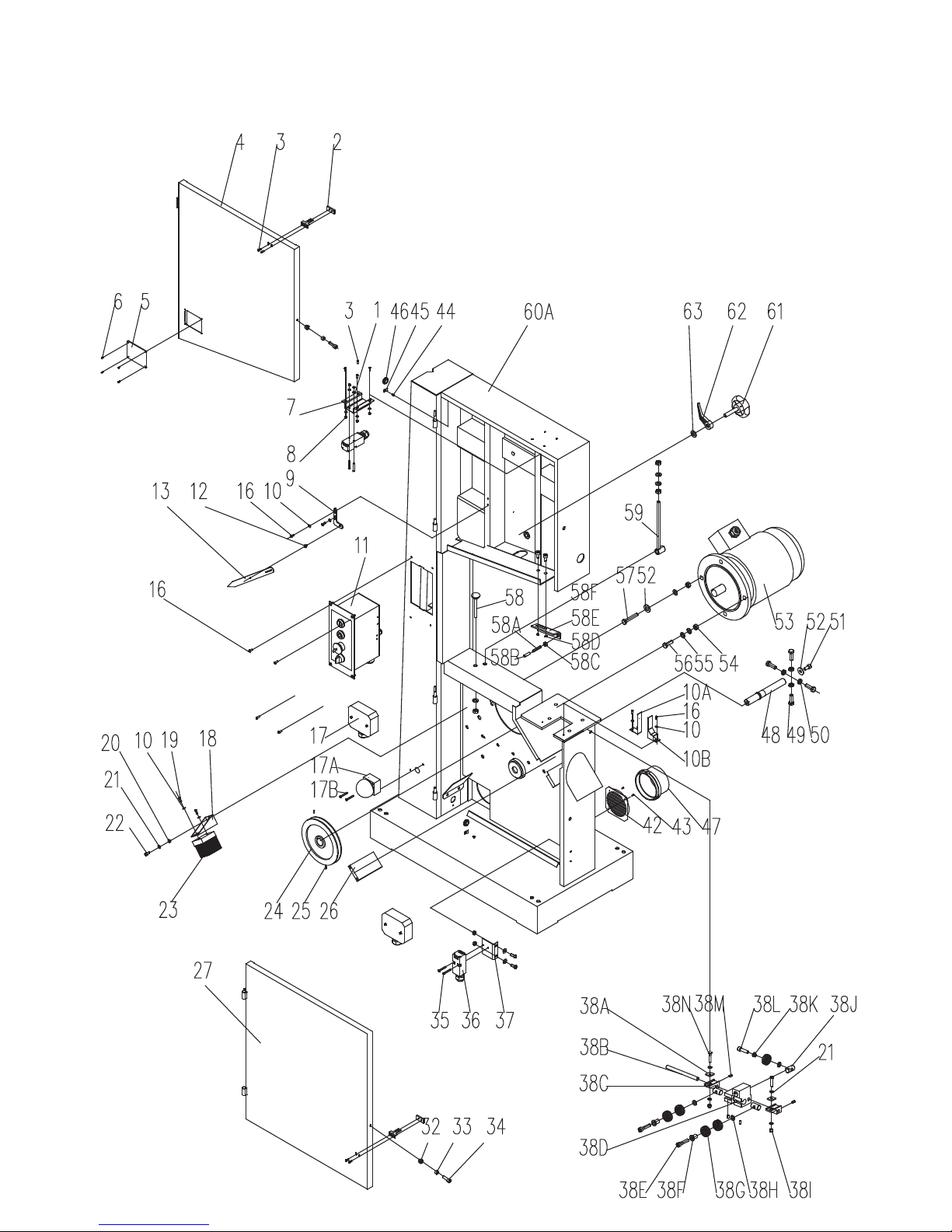
11. Parts Lists and Diagrams - 403/UK1 and 403/UK3
Frame Assembly

19
11. Parts Lists and Diagrams - 403/UK1 and 403/UK3
1 Flat washer WSH4GB97D1Z 8
2 Plate JL27010017 2
3 Pan head screw M4X10GB818Z 10
4 Upper door BS4001012001D-060U 1
5 Glass of window JL26010001 1
6 Self-plugging rivet RVT3X7GB12618A 4
7 Microswitch base JL26010012-124U 1
8 Hex bolt M4GB6170Z 8
9 Bracket JXBS2201010007 1
10 Flat washer WSH5GB97D1Z 6
10A Left cover BS5001010003 1
10B Right cover BS5001010004 1
11 403/UK1 Switch assembly BS500111800A 1
11 403/UK3 Switch assembly BS600111700A 1
12 Pointer screw JL26010010 1
13 Indicator BS4001010001-114X 1
16 Pan head screw M5X10GB818Z 8
17 Junction box BS5001014000 1
17A Foot switch LA42JQT-02F 1
17B Pan head screw M5X30GB818Z 2
18 Brush base JL29000009-124U 1
19 Self tapping screw ST4D8X16GB845Z 2
20 Hex nut M6GB6172D1Z 1
21 Flat washer WSH6GB97D1Z 7
22 Screw M6X12GB70D1Z 1
23 Brush JL29000004 1
24 Motor pulley JXBS1601020003 1
25 Set screw M6X10GB80B12D9 1
26 Blocking chip plate JXBS2002010014 1
27 Lower door BS4001012002B-060U 1
32 Lock nut M6GB889D1Z 2
33 Tube JL26010007 2
34 Screw M6X20GB70D1Z 2
35 Pan head screw M4X30GB818Z 4
36 Microswitch QKS8 2
37 Microswitch base JL27010016-124U 1
38A Plate JL22040004 2
38B Connection shaft BS5001032003 1
38C Bracket JL20043001 2
38D Lower Guide BS5001032002 1
38E Screw M8X40GB70D1Z 2
38F Tube JL26041002 2
38G Bearing BRG6201-2RSGB276 5
38H Flat washer WSH8GB97D1Z 3
38I Lock nut M6GB889D1Z 2
38J JL26041003 JL26041003 3
38K Bearing tube JL26041006 1
38L Screw M8X30GB70D1Z 1
38M Set screw M6X10GB80B12D9 4
38N Hex bolt M6X30GB5783Z 2
42 Suction grille JL20010019-001S 1
43 Self tapping screw ST3D5X9D5GB845Z 2
44 Pan head screw M4X10GB818Z 2
45 Cable board 1502014-02 2
46 Rubber bushing 1905010 2
47 Dust port JL20010007-001S 1
48 Lower shaft JXBS1601020002 1
49 Hex bolt M12X35GB5783Z 4
50 Nut M12GB6172D1Z 4
51 Screw M10X20GB70D1Z 1
52 Large washer WSH10GB96D1Z 2
53 Motor 2-YYH800152B 1
53 Motor 2-YSH905222D 1
54 Hex bolt M10GB6170Z 5
55 Flat washer WSH10GB97D1Z 6
56 Hex bolt M10X30GB5783Z 1
57 Hex bolt M10X70GB5783Z 1
58 Support screw JXBS2001010003 1
58A Lock screw M6X30GB77B12D9 1
58B Plastic tube JXBS2401010018 1
58C Nut M6GB6170Z 1
58D Nut M5GB6170Z 2
58E Connecting angle BS5001010002 1
58F Screw M5X16GB70D1Z 2
59 Shaft JXBS2001015001 1
60A Frame BS4001011000B-124U 1
61 Adjustment handle JXBS1602010006-001S 1
62 Locker JXBS1602010007-001S 1
63 Flat washer WSH12GB97D1Z 1
64 Dust blocking plate JL26030019 1
No. Description Part No Quantity No. Description Part No Quantity
Frame Assembly

20
70
65
66
67
68
69
71
66
67
68
64
65
72
73
74
11. Parts Lists and Diagrams - 403/UK1 and 403/UK3
65 Washer JXBS2201020004 2
66 Retaining ring CLP52GB893D1B 4
67 Bearing BRG6205-2RSGB276 4
68 Tube BS4001020004 2
69 Upper wheel BS4001021001-001G 1
70 Tyre BS4001021002 2
71 Blade BS4001020001 1
72 Belt BS4001020003 1
73 Lower wheel BS4001022001-001G 1
74 Screw M10X20GB70Z 2
No. Description Part Number Quantity No. Description Part Number Quantity
Driving System Assembly

21
11. Parts Lists and Diagrams - 403/UK1 and 403/UK3
75
76
77
78
79
80
81
95
96
97
98
99
1 02
1 03
1 04
1 05
1 06
1 07
1 08
1 09
1 10
1 11
84
1 00
1 01
8 2 8 3 84
85
86
87
88
89
90
91
83
93
92
94
1 12
75 Lock plate JXBS2001060001 1
76 Fence bracket JXBS2001060002-001G 1
77 Handle JXBS2201061000-001S 1
78 Screw M8X25GB70Z 2
79 Washer WSH8GB97D1Z 2
80 Fence guide BS5001060001 1
81 Rod JXBS2001060003 2
82 Hex nut JXBS2001060004 2
83 Washer WSH10GB97D1Z 5
84 Hex nut M10GB6170Z 4
85 Trunnion assembly JXBS2001031100 1
86 Nut M12X60GB77B 3
87 Large washer WSH12GB96Z 8
88 Hex nut M12GB6170Z 4
89 Trunnion JXBS2001031001 1
90 Lock nut JL29042004 1
91 Guide shaft JXBS2001031002 1
92 Large washer WSH6GB5287Z 2
93 Nut M6X10GB70Z 2
94 Bolt M12X100GB14Z 1
95 Washer WSH10GB97D1Z 2
96 Spring washer WSH10GB93Z 2
97 Washer WSH12GB97D1Z 1
98 Locking handle KTSB-1-A-M12X95 1
99 Gear shaft JMBS2201032200 1
100 Large washer WSH10GB96Z 2
101 Bolt M10X40GB5783Z 2
102 Hex nut M12GB6172Z 4
103 Nut M12X50GB77B 1
104 Rivet RVT2D5X5GB827C 2
105 Indicator JXBS2401031008 1
106 Scale JXBS2001031004A 1
107 Rivet RVT2D5X5GB827C 3
108 Table BS4001030001-001G 1
109 Nut M5X30GB77B 4
110 Table insert BS5001030001-001S 1
111 Lock nut M5GB889Z 4
112 Rip fence JXBS1601060002 1
No. Description Part Number Quantity No. Description Part Number Quantity
Table Assembly

22
11. Parts Lists and Diagrams - 403/UK1 and 403/UK3
1 40
1 13
1 14
1 15
1 16
1 17
1 18
1 19
1 20
1 2 1 122
123
124
125
126
127
128
129
130
131
132
133
139 1 3 8 1 3 6 1341 351 37
1 41
113 Spring washer WSH50GB1972B 8
114 Flat washer WSH24GB97D1Z 2
115 Plate BS5001040009 1
116 Roll pin PIN3X30GB879D1B 1
117 Thread rod BS4001040002 1
118 Bearing BRG51104GB301 2
119 Bracket BS5001040002 1
120 Knob 1904011 1
121 Bracket BS5001040005 1
122 Hand wheel JXBS2001040005-001S 1
123 Set screw M6X12GB80B 1
124 Pan head screw M10X30GB70Z 2
125 Spring washer WSH10GB93Z 2
126 Bracket BS5001040003 1
127 Sliding rod BS5001040001 2
128 Upper shaft BS4001040001 1
129 Bracket JXBS1401030001-001G 1
130 Set screw M8X20GB80B 1
131 Spring washer WSH10GB93B 2
132 Hex nut M10GB6170Z 2
133 Thread rod JXBS1801030007 1
134 Hex nut M12GB923Z 2
135 Spring washer WSH12GB93Z 2
136 Flat washer WSH12GB97D1Z 2
137 Bolt JXBS1801030006 2
138 Flat washer WSH10GB97D1Z 2
139 Lock nut M10GB889Z 2
140 Washer BS5001040007 1
141 Tube BS5001040006 1
No. Description Part Number Quantity No. Description Part Number Quantity
Blade Tension Assembly

23
11. Parts Lists and Diagrams - 403/UK1 and 403/UK3
142 Lock handle JL26040015-001S 1
143 Bracket JL26040008 1
144 Set screw M6X12GB77Z12D9 4
145 Gear 1501006 1
146 Plate JL26040007 1
147 Screw JL26040006 1
148 Cover BS5001050001 1
149 Screw M8X16GB70D1Z 4
150 Cover BS5001050002 1
151 Pan head screw M4X4GB823B 2
152 Rack JL26040001 1
153 Screw M4X10GB819D1Z 3
154A Bracket BS5001052001 1
155 Screw M8X20GB70D1Z 1
156A Guide post JL26041004 1
156B Screw M8X16GB70D1Z 1
156C Tube JL26041006 1
156D Screw M8X30GB70D1Z 1
156E Screw M8X40GB70D1Z 2
156F Tube JL26041002 2
156G Bearing BRG6201-2RSGB276 5
156H Flat washer WSH8GB97D1Z 3
156I Guide shaft JL26041003 3
156J Upper guide JL26041001 1
157 Composite bolt JL20061003A-001S 1
158 Small countersunk head riveted nut M6X15GB/T17880D3Z 1
161A Blade guard BS4001051000C-105U 1
162A Guide post BS4001050001B 1
164 Screw M5X10GB70D1Z 2
165 Large washer WSH5GB96D1Z 2
167 Large washer WSH6GB96D1Z 1
169 Screw M6X16GB70D1Z 2
170 Pan head screw M5X10GB818B 3
171 Handle 1501009-20001S 1
172 Large hand wheel JL26030012-001S 1
173 Retaining ring CLP12GB884B 1
174 Set screw M5X8GB78Z12D9 1
175 Tube JL26040003 1
176 Worm JL26040004 1
177 Hex bolt M8X20GB5783Z 4
178 Large washer WSH8GB96D1Z 4
179 Protective cover BS5001052002A 1
180 Flat washer WSH5GB97D1Z 4
181 Screw M5X10GB818Z 4
No. Description Part Number Quantity No. Description Part Number Quantity
Upper Guide Assembly

24
12. Parts Lists and Diagrams - 503/UK3
Frame Assembly

25
12. Parts Lists and Diagrams - 503/UK3
1 Frame BS5001011000C-124U 1
2 Plate JL27010017 2
3 Pan head screw M4X10GB818Z 10
4 Upper door BS5001012001C-060U 1
5 Inspection window JL26010001 1
6 Self-plugging rivet RVT3X7GB12618A 4
7 Microswitch base JL26010012-124U 1
8 Flat washer WSH4GB97D1Z 8
9 Hex bolt M4GB6170Z 8
10 Bracket JXBS2201010007 1
11 Flat washer WSH5GB97D1Z 6
12 Pan head screw M5X10GB818Z 8
13 Pointer screw JL26010010 1
14 Indicator JXBS2401010002-114X 1
15 Switch assembly BS600111700A 1
16 Left cover BS5001010003 1
17 Right cover BS5001010004 1
18 Junction box JXPS1201090009 1
18A Foot switch LA42JQT-02F 1
18B Pan head screw M5X30GB818Z 2
19 Brush base JL29000009-124U 1
20 Self tapping screw ST4D8X16GB845Z 2
21 Hex nut M6GB6172D1Z 1
22 Flat washer WSH6GB97D1Z 7
23 Screw M6X12GB70D1Z 1
24 Brush JL29000004 1
25 Motor pulley BS5001020003-001G 1
26 Screw M8X10GB80B12D9 2
27 Plate JXBS2401010014 1
28 Lower door BS5001012002B-060U 1
33 Pan head screw M4X30GB818Z 4
34 Microswitch QKS8 2
35 Microswitch base JL27010016-124U 1
36 Lock nut M6GB889D1Z 2
37 Tube JL26010007 2
38 Screw M6X20GB70D1Z 2
38A Plate JL22040004 2
38B Connection shaft BS5001032003 1
38C Bracket JL20043001 2
38D Lower Guide BS5001032002 1
38E Screw M8X40GB70D1Z 2
38F Tube JL26041002 2
38G Bearing BRG6201-2RSGB276 5
38H Large washer WSH8GB97D1Z 3
38I Lock nut M6GB889D1Z 2
38J Guide shaft JL26041003 3
38K Bearing tube JL26041006 1
38L Screw M8X30GB70D1Z 1
38M Set screw M6X10GB80B12D9 4
38N Hex bolt M6X30GB5783Z 2
43 Suction grille JL20010019-001S 1
44 Self tapping screw ST3D5X9D5GB845Z 2
45 Suction JL20010007-001S 1
46 Lower shaft JXBS2001020002 1
47 Hex bolt M12X35GB5783Z 4
48 Hex nut M12GB6172D1Z 4
49 Screw M10X20GB70D1Z 1
50 Large washer WSH10GB96D1Z 1
51 Motor YSH105304B 1
52 Hex bolt M10GB6170Z 5
53 Hex bolt M10X40GB5783Z 1
54 Hex bolt M10X70GB5783Z 1
55 Large washer WSH10GB96D1Z 1
56 Flat washer WSH10GB97D1Z 6
57 Shaft BS5001015001 1
58 Support screw JXBS2001010003 1
58A Set screw M6X30GB77B12D9 1
58B Plastic tube JXBS2401010018 1
58C Screw M6GB6170Z 1
58D Screw M5GB6170Z 2
58E Connecting angle BS5001010002 1
58F Screw M5X16GB70D1Z 2
59 JXBS2401010006-001S JXBS2401010006-001S 1
60 Locker JXBS2401010007-001S 1
61 Flat washer WSH12GB97D1Z 1
62 Dust blocking plate JL26030019 1
No. Description Part Number Quantity No. Description Part Number Quantity
Frame Assembly

26
12. Parts Lists and Diagrams - 503/UK3
63
64
65
66
67
68
69
70
71
72
63
64
65
66
67
69
63 Screw M10X20GB70Z 2
64 Washer JXBS2201020004 2
65 Retaining ring CLP52GB893D1B 4
66 Bearing BRG6205-2RSGB276 4
67 Tube BS5001022002 2
68 Upper wheel BS5001021001A-001G 1
69 Tyre BS5001021002A 2
70 Blade BS5001020001 1
71 Belt BS5001020002 1
72 Lower wheel BS5001022001A-001G 1
No. Description Part Number Quantity No. Description Part Number Quantity
Driving System Assembly

27
12. Parts Lists and Diagrams - 503/UK3
73
74
75
76
77
78
79
80
81 82 83
84
85
86
87
88
89
90
91
92
93
948295
96
97
98
99
100
82
83
101 1 02
1 03
104
105
1 06
1 07
1 08
1 09
73 Rip fence JL26060002C 1
74 Lock plate JXBS2001060001 1
75 Screw M8X25GB70Z 2
76 Washer WSH8GB97D1Z 2
77 Fence bracket JXBS2001060002-001G 1
78 Handle JXBS2201061000-001S 1
79 Fence guide JXBS2001060005 1
80 Rod JXBS2001060003 2
81 Hex nut JXBS2001060004 2
82 Washer WSH10GB97D1Z 7
83 Hex nut M10GB6170Z 4
84 Trunnion Assembly JXBS2001031100 1
85 Nut M12X60GB77B 3
86 Hex nut M12GB6172Z 4
87 Large washer WSH12GB96Z 8
88 Hex nut M12GB6170Z 4
89 Nut M12X50GB77B 1
90 Nut M3X5GB818Z 2
91 Indicator JXBS2401031008 1
92 Scale JXBS2001031004A 1
93 Rivet RVT2D5X5GB827C 3
94 Trunnion JXBS2001031001 1
95 Lock nut JL29042004 1
96 Guide shaft JXBS2001031002 1
97 Nut M6X10GB70Z 2
98 Large washer WSH6GB5287Z 2
99 Bolt M12X100GB14Z 1
100 Spring washer WSH10GB93Z 2
101 Washer WSH12GB97D1Z 1
102 Locking handle KTSB-1-A-M12X95 1
103 Gear shaft JMBS2201032200 1
104 Large washer WSH10GB96Z 2
105 Bolt M10X40GB5783Z 2
106 Table BS5001030002-001G 1
107 Lock nut M5GB889Z 4
108 Table insert BS5001030001-001S 1
109 Nut M5X30GB77B 4
No. Description Part Number Quantity No. Description Part Number Quantity
Table Assembly

28
12. Parts Lists and Diagrams - 503/UK3
1 12
1 13
1 14
1 15
1 16
1 17
1 18
1 19
1 20
1 21
1 22
1 23
1 24
1 25
1 26
1 27
1 28
1 29
1 34
135
1 30
1 31
1 32
1 33
1 36 137 138 139 1 40
112 Washer BS5001040007 1
113 Tube BS5001040006 1
114 Spring washer WSH50GB1972B 8
115 Flat washer WSH24GB97D1Z 1
116 Plate BS5001040009 1
117 Roll pin PIN3X30GB879D1B 1
118 Thread rod BS5001040004 1
119 Bearing BRG51104GB301 2
120 Bracket BS5001040002 1
121 Knob 1904011 1
122 Bracket BS5001040005 1
123 Hand wheel JXBS2001040005 1
124 Set screw M6X12GB78B 1
125 Pan head screw M10X30GB70Z 2
126 Spring washer WSH10GB93Z 2
127 Bracket BS5001040003 1
128 Sliding rod BS5001040001 2
129 Upper shaft BS5001040008 1
130 Bracket JXBS1401030001 1
131 Set screw M8X20GB80B 1
132 Spring washer WSH10GB93B 2
133 Hex nut M10GB6170Z 2
134 Thread rod JXBS1801030007 1
135 Lock nut M10GB889Z 2
136 Spring washer WSH10GB97D1Z 2
137 Bolt JXBS1801030006 2
138 Flat washer WSH12GB97D1Z 2
139 Spring washer WSH12GB93Z 2
140 Hex nut M12GB923Z 2
No. Description Part Number Quantity No. Description Part Number Quantity
Blade Tension Assembly

29
12. Parts Lists and Diagrams - 503/UK3
141 Hex bolt M8X20GB5783Z 4
142 Large washer WSH8GB96D1Z 4
143 Lock handle JL26040015-001S 1
144 Bracket JL26040008 1
145 Set screw M6X12GB77Z12D9 4
146 Gear 1501006 1
147 Plate JL26040007 1
148 Screw JL26040006 1
149 Cover BS5001050001 1
150 Screw M8X16GB70D1Z 4
151 Cover BS5001050002 1
152 Pan head screw M4X4GB823B 2
153 Rack BS6001050001 1
154 Screw M4X10GB819D1Z 3
155A Bracket BS5001052001 1
156 Screw M8X20GB70D1Z 1
156A Guide post JL26041004 1
156B Screw M8X16GB70D1Z 1
156C Tube JL26041006 1
156D Screw M8X30GB70D1Z 1
156E Screw M8X40GB70D1Z 2
156F Tube JL26041002 2
156G Bearing BRG6201-2RSGB276 5
156H Flat washer WSH8GB97D1Z 3
156I Guide shaft JL26041003 3
156J Upper guide JL26041001 1
159 Large washer WSH6GB96D1Z 1
160 Composite bolt JL20061003A-001S 1
161 Nut M6X15GB/T17880D3Z 1
164A Blade guard BS5001051000B-105U 1
166 Large washer WSH5GB96D1Z 2
167 Screw M5X10GB70D1Z 2
169 Screw M6X16GB70D1Z 2
170A Guide post BS5001050003B 1
171 Pan head screw M5X10GB818B 2
172 Handle 1501009-20001S 1
173 Large hand wheel JL26030012-001S 1
174 Tube JL26040003 1
175 Screw-locked ring CLP12GB884B 1
176 Set screw M5X8GB78Z121D9 1
177 Worm JL26040004 1
178 protective cover BS5001052002A 1
179 Flat washer WSH5GB97D1Z 4
180 Screw M5X10GB818Z 4
No. Description Part Number Quantity No. Description Part Number Quantity
Upper Guide Assembly
30
13. Parts Lists and Diagrams - 603/UK3
Frame Assembly

31
13. Parts Lists and Diagrams - 603/UK3
Frame Assembly
1 Flat washer WSH4GB97D1Z 8
2 Plate JL27010017 2
3 Pan head screw M4X10GB818Z 10
4 Upper door BS6001012001C-060U 1
5 Inspection window JL26010001 1
6 Self-plugging rivet RVT3X7GB12618A 4
7 Microswitch base JL26010012-124U 1
8 Hex bolt M4GB6170Z 8
9 JXBS2201010007 JXBS2201010007 1
10 Flat washer WSH5GB97D1Z 6
10A Left cover BS5001010003 1
10B Right cover BS5001010004 1
11 Switch assembly BS600111700A 1
12 Pointer screw JL26010010 1
13 Indicator JXBS2401010002-114X 1
16 Pan head screw M5X10GB818Z 8
17 Junction box JXPS1201090009 1
17A Foot switch LA42JQT-02F 1
17B Pan head screw M5X30GB818Z 2
18 Brush base JL29000009-124U 1
19 Self tapping screw ST4D8X16GB845Z 2
20 Hex nut M6GB6172D1Z 1
21 Flat washer WSH6GB97D1Z 7
22 Screw M6X12GB70D1Z 1
23 Brush JXBS2401010017 1
24 Motor pulley BS6001020002 1
25 Set screw M8X10GB80B 2
26 Blocking chip plate JXBS2401010014 1
27 Lower door BS6001012002B-060U 1
32 Lock nut M6GB889D1Z 2
33 Tube JL26010007 2
34 Screw M6X20GB70D1Z 2
35 Pan head screw M4X30GB818Z 4
36 Microswitch QKS8 2
37 Microswitch base JL27010016-124U 1
38A Plate JL22040004 2
38B Connection shaft BS5001032003 1
38C Bracket JL20043001 2
38D Lower guide BS5001032002 1
38E Screw M8X40GB70D1Z 2
38F Tube JL26041002 2
38G Bearing BRG6201-2RSGB276 5
38H Flat washer WSH8GB97D1Z 3
38I Lock nut M6GB889D1Z 2
38J Guide shaft JL26041003 3
38K Bearing tube JL26041006 1
38L Screw M8X30GB70D1Z 1
38M Set screw M6X10GB80B12D9 4
38N Hex bolt M6X30GB5783Z 2
42 Suction grille JL20010019-001S 1
43 Self tapping screw ST3D5X9D5GB845Z 2
44 Pan head screw M4X10GB818Z 2
45 Cable board 1502014-02 2
46 Rubber bushing 1905010 2
47 Dust port JL20010007-001S 1
48 Lower shaft BS6001020001 1
49 Hex bolt M12X35GB5783Z 4
50 Nut M12GB6172D1Z 4
51 Screw M10X20GB70D1Z 1
52 Large washer WSH10GB96D1Z 2
53 Motor YSH115404B 1
54 Hex bolt M10GB6170Z 5
55 Flat washer WSH10GB97D1Z 6
56 Hex bolt M10X40GB5783Z 1
57 Hex bolt M10X70GB5783Z 1
58 Support screw BS6001010001 1
58A Lock screw M6X30GB77B12D9 1
58B Plastic tube JXBS2401010018 1
58C Nut M6GB6170Z 1
58D Nut M5GB6170Z 2
58E Connecting angle BS5001010002 1
58F Screw M5X16GB70D1Z 2
59 Shaft BS6001014001 1
60A Frame BS6001011000C-124U 1
61 Adjustment handle JXBS2401010006-001S 1
62 Locker JXBS2401010007-001S 1
63 Flat washer WSH12GB97D1Z 1
No. Description Part Number Quantity No. Description Part Number Quantity

32
70
66
67
68
69
64
65
64
65
66
67
68
72
71
73
13. Parts Lists and Diagrams - 603/UK3
64 Screw M10X20GB70Z 2
65 Washer JXBS2201020004 2
66 Retaining ring CLP62GB893D1B 4
67 Bearing BRG6206GB276LLU 4
68 Tube BS6001022002 2
69 Upper wheel BS6001021001-001G 1
70 Tyre BS6001021002 2
71 Blade BS6001020003 1
72 Belt BS6001020004 1
73 Lower wheel BS6001022001A-001G 1
No. Description Part Number Quantity No. Description Part Number Quantity
Driving System Assembly

33
13. Parts Lists and Diagrams - 603/UK3
74
75
76
77
78
79
80
81
8 2 8 3 84
89
90
91
92
93
94
95
96
97
98
99
100
1 01
1 02
1 03
1 06
1 04
1 05
88
87
86
85
1 07
74 Rip fence JXBS1803060001 1
75 Lock plate JXBS2001060001 1
76 Fence bracket JXBS2001060002-001G 1
77 Handle JXBS2201061000-001S 1
78 Screw M8X25GB70Z 2
79 Washer WSH8GB97D1Z 2
80 Fence guide BS6001060001 1
81 Rod JXBS2001060003 2
82 Hex nut JXBS2001060004 2
83 Washer WSH10GB97D1Z 4
84 Hex nut M10GB6170Z 2
85 Slider JXBS2402031002-124L 1
86 Nut M12X60GB77B 4
87 Large washer WSH12GB96Z 8
88 Hex nut M12GB6170Z 4
89 Support JXBS2402031001-124L 1
90 Hex Bolt M12X45GB30Z 1
91 Large pad JXBS2401031007 1
92 Support JXBS2402031001-124L 1
93 Hex Bolt M10X45GB5783Z 2
94 Hex nut M10GB6170Z 2
95 Large washer WSH10GB96Z 2
96 Spring washer WSH10GB93Z 2
97 Nut M3X5GB818Z 2
98 Angle pointer JXBS2402031004 1
99 Angle Signs JXBS2402031005 1
100 Rivet RVT2D5X5GB827C 3
101 Lock nut M5GB889Z 4
102 Table insert BS5001030001-001S 1
103 Nut M5X30GB77B 4
104 Large washer WSH8GB96Z 2
105 Nut M8X16GB70Z 2
106 Table BS6001030001-001G 1
107 Extension table JXBS2402030002-001U 1
No. Description Part Number Quantity No. Description Part Number Quantity
Table Assembly

34
13. Parts Lists and Diagrams - 603/UK3
114
109
133
108
109
110
111
112
113
114
115
116
117
118
119
120
121
122
123
1 24
1 25
126
127
128
129
130
131
132
108 Spring washer WSH12GB93Z 2
109 Flat washer WSH12GB97D1Z 4
110 Lock nut M12GB889Z 2
111 Bolt JXBS2201030001 2
112 Thread rod JXBS2201030002 1
113 Hex nut M10GB6170Z 2
114 Spring washer WSH10GB93Z 4
115 Set screw M8X20GB80B 1
116 Bracket JXBS2201030003-001G 1
117 Upper shaft BS6001040001 1
118 Set screw M8X8GB80B 1
119 Sliding rod JXBS2201030004 2
120 Upper shaft JXBS2201030008 1
121 Set screw M10X30GB70Z 2
122 Set screw M6X12GB80B 1
123 Hand wheel JXBS2001040005-001S 1
124 Thread rod JXBS2401040002 1
125 Roll pin PIN3X18GB879B 1
126 Bearing JXBS2201030011 1
127 Flat washer JXBS2201030007 1
128 Roll pin PIN3X30GB879D1B 1
129 Flat washer WSH24GB97D1Z 2
130 Sliding rod JXBS2201030010 1
131 Tube JXBS2201030011 1
132 Spring washer WSH50GB1972B 4
133 Hex nut M12GB923Z 2
No. Description Part Number Quantity No. Description Part Number Quantity
Blade Tension Assembly

35
13. Parts Lists and Diagrams - 603/UK3
134 Large washer WSH8GB96D1Z 4
135 Lock handle JL26040015-001S 1
136 Bracket JL26040008 1
137 Set screw M6X10GB77B12D9 4
138 Gear 1501006 1
139 Plate JL26040007 1
140 Screw JL26040006 1
141 Cover BS5001050001 1
142 Screw M8X16GB70D1Z 4
143 Cover BS5001050002 1
144 Pan head screw M4X4GB823B 2
145 Rack BS6001050001 1
146 Screw M4X10GB819D1Z 3
147A Bracket BS5001052001 1
148 Screw M8X20GB70D1Z 1
149A Guide post JL26041004 1
149B Screw M8X16GB70D1Z 1
149C Tube JL26041006 1
149D Screw M8X30GB70D1Z 1
149E Screw M8X40GB70D1Z 2
149F Tube JL26041002 2
149G Bearing BRG6201-2RSGB276 5
149H Flat washer WSH8GB97D1Z 3
149I Guide shaft JL26041003 3
149J Upper guide JL26041001 1
151 Large washer WSH6GB96D1Z 1
152 Composite bolt JL20061003A-001S 1
153 Nut M6X15GB/T17880D3Z 1
156A Blade guard BS6001051000B-105U 1
158 Screw M5X10GB70D1Z 2
159 Large washer WSH5GB96D1Z 2
161 Screw M6X16GB70D1Z 2
162A Guide post BS6001050002B 1
163 Pan head screw M5X10GB818B 3
164 Handle 1501009-20001S 1
165 Hand wheel JL26030012-001S 1
166 Ring CLP12GB884B 1
167 Set screw M5X8GB78B12D9 1
168 Tube JL26040003 1
169 Worm JL26040004 1
170 Hex bolt M8X20GB5783Z 4
171 Flat washer WSH5GB97D1Z 4
172 Screw M5X10GB818Z 4
173 protective cover BS5001052002A 1
No. Description Part Number Quantity No. Description Part Number Quantity
Upper Guide Assembly

36
14. Electrical Connection and Wiring Diagrams
Machines supplied for use in the UK are fitted with a 3 pin plug conforming
to BS1363, fitted with a fuse conforming to BS1362 and appropriate to the
current rating of the machine.
Machines supplied for use in other countries within the European Union are
fitted with a 2 pin Schuko plug conforming to CEE 7/7.
Machines supplied for use in Australia and New Zealand are fitted with a 3
pin plug conforming to AS/NZS3112.
In all cases, if the original plug or connector has to be replaced for any
reason, the wires within the mains power cable are colour coded as follows:
230 V (Single Phase)
Brown: Live (L)
Blue: Neutral (N)
Green and Yellow: Earth (E)
The wire coloured brown must always be connected to the terminal marked
‘L’ or coloured red.
The wire coloured blue must always be connected to the terminal marked ‘N’
or coloured black.
The wire coloured green and yellow must always be connected to the
terminal marked ‘E’ or with the earth symbol:
or coloured green / green and yellow.
It is important that the machine is effectively earthed. Some machines will be
clearly marked with the double insulated logo:
In this case there will not be an earth wire within the circuit.
In the case of the BS1363 plug for use in the UK, always ensure that it is
fitted with a fuse conforming to BS1362 appropriate to the rating of the
machine. If replacing the original fuse, always fit a fuse of equivalent rating
to the original. Never fit a fuse of a higher rating than the original. Never
modify the fuse or fuse holder to accept fuses of a different type or size.
Where the current rating of the machine exceeds 13 A at 230 V, or if the
machine is designated for use on a 400 V 3 phase supply a connector
conforming to BS4343 (CEE17 / IEC60309) will be used.
230 V machines will be fitted with a blue 3 pin connector. The wiring for this
type of this connector will be the same as shown above.
400 V, 3 phase machines will be fitted with a red 4 or 5 pin connector. The
wiring for this type of connector is as shown below:
400 V (3 phase)
Brown: Live (L1)
Black: Live (L2)
Grey: Live (L 3)
Blue: Neutral (N)
Green and Yellow: Earth (E)
The wire coloured brown must always be connected to the terminal
marked ‘L1’.
The wire coloured black must always be fitted to the terminal
marked ‘L2’.
The wire coloured grey must always be connected to the terminal
marked ‘L3’.
The wire coloured blue must always be connected to the terminal
marked ‘N’ or coloured black.
The wire coloured green and yellow must always be connected to the
terminal marked ‘E’ or with the earth symbol
If in doubt about the connection of the electrical supply, always consult a
qualified electrician.

37
-KM1
33
34
-SA1
-KT1
14
13
-KT1
-SA1
-KM1
13
14
-KT1
-M1
4
5
-KM1
L1T1L2T2L3
T3
-ST1
-SB1
-KM1
A1
A2
-SS1
-SS2
-SS3
-SB2
-SA1
L
12121417 16 15
N
N
18
19
L
21
10
N
20
1L
1N
L
L
N
M
-M1
13
L
N
10
10
1
2
3
4
5
-SA1
X2
X1
14. Electrical Connection and Wiring Diagrams
403/UK1
403/UK3, 503/UK3 and 603/UK3
-KM1
33
34
-SA1
-KT1
14
13
-KT1
-SA1
-KM1
13
14
-KT1
-M1
4
5
-KM1
L1T1L2T2L3
T3
M
-M1
UVW
-ST1
-SB1
-KM1
A1
A2
-SS1
-SS2
-SS3
-SB2
-SA1
111 21 21417 16 1518
19
L3
21
10
20
L3
L2
U1
V1
W1
L1
L1
13
L2
10
10
L3
-SA1
X2
X1
N
N
N

38
EU Declaration of Conformity
Cert No: EU / 403/UK1 / 1
Record Power Ltd,
Centenary House, 11 Midland Way, Barlborough Links,
Chesterfield, Derbyshire, S43 4XA, UK
declares that the machinery described:-
1. Type: Bandsaw
2. Model numbers: 403/UK1
3. Serial No .........................................................................
Conforms with the following directives:-
MACHINERY DIRECTIVE 2006/42/EC
ELECTROMAGNETIC 2004/108/EC
COMPATIBILITY DIRECTIVE EN 1807-1:2013
EN60204-1:2006+A1:2009+AC:2010
and conforms to the machinery example for which the
EC Type-Examination Certificate No. 17706052 002, BM 50311972 0001
has been issued by TUV Rheinland LGA Products GmbH
at: Tillystrasse 2, D90431 Nürnberg
and complies with the relevant essential health and safety requirements.
Signed ............................................................... Dated: 01/10/2016
Andrew Greensted
Managing Director

39
EU Declaration of Conformity
Cert No: EU / 403/UK3, 503/UK3 603/UK3 / 1
Record Power Ltd,
Centenary House, 11 Midland Way, Barlborough Links,
Chesterfield, Derbyshire, S43 4XA, UK
declares that the machinery described:-
1. Type: Bandsaw
2. Model numbers: 403/UK3, 503/UK3 and 603/UK3
3. Serial No .........................................................................
Conforms with the following directives:-
MACHINERY DIRECTIVE 2006/42/EC
ELECTROMAGNETIC 2004/108/EC
COMPATIBILITY DIRECTIVE EN 1807-1:2013
EN60204-1:2006+A1:2009+AC:2010
and conforms to the machinery example for which the
EC Type-Examination Certificate No. 17706052 002, BM 50312551 0001
has been issued by TUV Rheinland LGA Products GmbH
at: Tillystrasse 2, D90431 Nürnberg
and complies with the relevant essential health and safety requirements.
Signed ............................................................... Dated: 01/12/2017
Andrew Greensted
Managing Director

Record Power Ltd, Centenary House, 11 Midland Way, Barlborough Links, Chesterfield, Derbyshire S43 4XA
Tel: +44 (0) 1246 571 020 Fax: +44 (0) 1246 571 030 www.recordpower.co.uk
To register a product and find your local stockist visit
recordpower.info
Made in China
Industrial Woodworking Machinery
 Loading...