


Woodworking Bandsaws
Instruction Manual
352SB
501S
401S
581S
440R
681S

Index
1 GENERAL INFORMATION
1.1 Foreword
1.2 Warranty
2 MACHINE DESCRIPTION
2.1 Machine identification
2.2 CE Certificate
2.3 Technical specification
2.4 Recommended protective clothing
2.5 Noise emission
2.6 Prescribed use of the machine
2.7 Hazards
3 INSTALLATION
3.1 Hoisting and unloading
3.2 Position of the machine
3.3 Electrical connection - start up
3.4 Connecting the dust extraction system
4 USING THE MACHINE
4.1 Principal machine groups
4.2 Choice and maintenance of blade
4.3 Blade mounting and adjustment
4.4 Setting the blade guides
4.5 Table insert and wooden insert for aspiration
4.6 Cutting direction and parallelism
4.7 Tilting the worktable
5 SAFETY ADVICE
5.1 Safety devices and guards
5.2 Face cutting & cutting of short pieces
5.3 Cutting of round pieces
5.4 Wedge cutting
5.5 Cutting of wedge-shaped lengths
6 BRAKING SYSTEM
6.1 Maintenance and adjustment of the braking system
7 MAINTENANCE
8 TROUBLE SHOOTING
9 ORDERING SPARE PARTS
9.1 Drive belts and ball bearing spare part numbers
10 DIAGRAMS & COMPONENTS

1. General Information
1.1 FOREWORD
This manual must be read and understood before operating the machine. This will provde a better working knowledge of the machine,
for increased safety and to obtain the best results.
1.2 WARRANTY
The warranty period is 12 months from date of purchase and covers the repair or replacement of parts due to manufacturers defects.
Proof of purchase will be required when making a claim.
The warranty does not cover:
• Accidental damage
• Damage caused by incorrect installation or incorrect electrical connection.
• Damage caused by negligence misuse or repairs by an unauthorised person.
• Consumable parts, such as blades, belts, bearings etc
The warranty is valid for 12 months from the date of purchase of the machine.
2. Machine Description
2.1 MACHINE IDENTIFICATION
There is a metallic identification plate fixed to the machine, containing the manufacturer's data, year of construction,
serial number and blade data.
2.2 CE CERTIFICATE
Certification of “ CE “ conformity issued by : I.N.R.S. , Av. de Bourgogne B.P. 27 , VANDOEUVRE CEDEX, FRANCE
2.3 TECHNICAL SPECIFICATION
352SB* 401S 440R 501S 581S 681S 781S
Bandwheels Dia. mm 400 400 440 500 600 700 800
Bandwheels Speed RPM 900 900 800 800 750 720 640
Motor Power HP 1
1
Cutting Depth mm 270 400 400 300 400 400 450
Cutting Width mm 390 390 480 480 580 680 780
Table Size mm 400x500 400x500 500x640 500x640 600x830 700x970 750x1100
Table Tilt 0-20º 0-20º 0-20º 0-20º 0-20º 0-20º 0-20º
Blade Length (Min) 3560mm / 141” 3785mm / 149” 4060mm / 160” 4170mm / 165” 4610mm / 182” 5100mm / 201” 5750mm / 227”
Blade Length (Max) 3640mm / 143” 3850mm / 151" 4170mm / 164” 4280mm / 168” 4680mm / 184” 5150mm / 203” 5820mm / 229”
Blade Width mm 6 - 30 6 - 30 6 - 50 6 - 35 6 - 35 6 - 40 6 - 45
1
/
(1 phase) 3 (1 phase) 3 (1 phase) 3 (1 phase) 3 (1 phase) 3 (1 phase) 5
2
1
/
(3 phase)
2
3 (3 phase) 5 (3 phase) 3 (3 phase) 4 (3 phase) 4 (3 phase)
1
/
(3 phase)
2
Machine Dimensions cm 77x52x179 77x52x179 85x59x197 87x60x197 100x79x200 118x80x220 128x85x245
Packing Dimensions cm 189x53x84 189x53x84 199x53x84 207x52x94 210x55x107 230x60x120 255x65x125
Nett Weight kg 145 157 236 200 280 330 510
352SB* Additional features and educational safety system
• Ceramic blade guide system
• Two speed motor in 3 phase model
• Kickstop
Please note: the ceramic guide system is available on all bandsaws as on optional extra.
• Lockable isolator
• Lockable keyswitch

2.4 RECOMMENDED PROTECTIVE CLOTHING
• Gloves for moving work material and when carrying out the blade changes;
• Non-slip shoes;
• Protective eye glasses.
2.5 NOISE EMISSION
The measurements of noise, in the working position and during operation, were carried out under the standard ISO 7960 annex "J":
Instantaneous acoustic pressure <130.0 dB
The value of the noise level indicated is an emission level and doesn’t necessarily represent safe working levels.
Although there is a relationship between emission levels and exposure levels, it isn't precise enough to use in a way to determine
whether it is necessary, or not, to implement further precautions. The factors that determine the true exposure level to operators are:
the amount of exposure time, the characteristics of the working environment, other sources of dust and noise etc..
The permitted exposure level limits vary from country to country. this information allows the machine user to better evaluate the
dangers and risks.
2.6 PRESCRIBED USE OF THE MACHINE
The machine was designed for cutting solid wood, wood derivates, materials similar to cork, hard rubber and hard plastic materials
using suitable blades.
Consult Record Power on Tel:0870 770 1777 for advice on the most suitable blade selection. See section 4.2.
THESE MACHINES MUST NOT BE USED TO CUT OTHER MATERIALS
THESE MACHINES MUST NOT BE USED TO CUT METALS
2.7 HAZARDS
ATTENTION Bandsaws still present risks that cannot be eliminated by the manufacturer. Therefore the user must be aware that wood
working machines are dangerous if not used with care and all safety precautions adhered to.
We recommend you to study the information given in HSE document: “Safety in the use of narrow bandsaws”
3. Installation
Sling 2000kg
3.1 HOISTING & LIFTING
The machine can be lifted using a forklift truck, placing the forks under the feet
or by using a “SLING”, as shown, with a
lifting capability of 2000 Kg.
Timber
3.2 POSITIONING THE MACHINE
For a correct and rational organisation of the work area :
• Install the machine in an area that will not amplify vibration or noise
• Verify that the work area is adequately illuminated.
• When placed between other machinery there should be a space of at least 80 cm. It is necessary to anticipate sufficient space for
cutting long work pieces traversly and for the fitting of rollers or other types of support,in front and at the rear of the table.
• The bases of the machines are provided with four threaded holes for levelling, the screws are provided with the machine.
There are also four holes for fixing the machine to the floor. When fixing to the floor it is recommended not to over tighten the fixtures
to avoid increasing vibration.It is also advisable to place anti-vibration materials between the floor and the feet of the machine.
3.3 ELECTRICAL CONNECTION - START UP
Electrical installation should be carried out by competent, qualified personnel.
The mains connection should be made using the terminal box as shown in FIG. 9 pos. E
Ensure that the mains supply corresponds with that of the machine, use cables of a section suitable for the power of the motor. For a
supply tension of 400 V the minimum section recommended is 2.5 mm, including the earth wire.
For a mains supply of 230 V or a power rating greater than 15 A it will be necessary to increase the section
of the connecting cables .
Connect the phase wires to the terminals R- S - T (L1 - L2 - L3) and the earth wire to the earth terminal.
On initial start-up check the direction of rotation, if it is incorrect then invert the two phase wires (for machines with 3 phase supply).
Direction of rotation of machines with single-phase supply is pre-determined during production .
On completion of the installation check that the terminal box is closed correctly and that the plug points are locked.
Starting the machine :
For the models 352SB, 401S, 440R, 501S, 581S, 681S, 781S:
Turn the isolator switch located at the rear of the machines FIG. 9 pos. E, to position “
shows that there is electrical power: turn the starter switch
To stop the machine press the stop button. Ensure before start uo the brake switch is in the on position (the machine will not start
with brake in the off postion)
PLEASE NOTE: 352SB 3 phase (2 speed) model the speed selector switch must be set at zero to switch the machine on. It is then
started by turning the speed selection switch to speed 1 or 2.
For the model 941S:
Turn isolator switch “
that there is electrical power. Turn switch “
machine reaches normal running speed, then turn to position “
turn Switch “
In case of emergency shut-off or power failure, it is necessary to turn the starter control (switch “
up procedure.
IMPORTANT: machines will not start with the doors open and will automatically stop if doors are opened during operation.
T” back to “O“.
E” (FIG. 9) located at the rear of the machine to position “1”, the white indicator light on the front panel shows
M” into position “1”. Now turn and hold switch “T” (FIG. 11) to position “Y” until the
“M” to position “1” to start-up the machine (FIG. 10).
∆”. Average time to reach normal speed: 4-8 seconds. To switch off,
.
1“, the white indicator light on the front panel
T”) back to “O” and repeat the start-
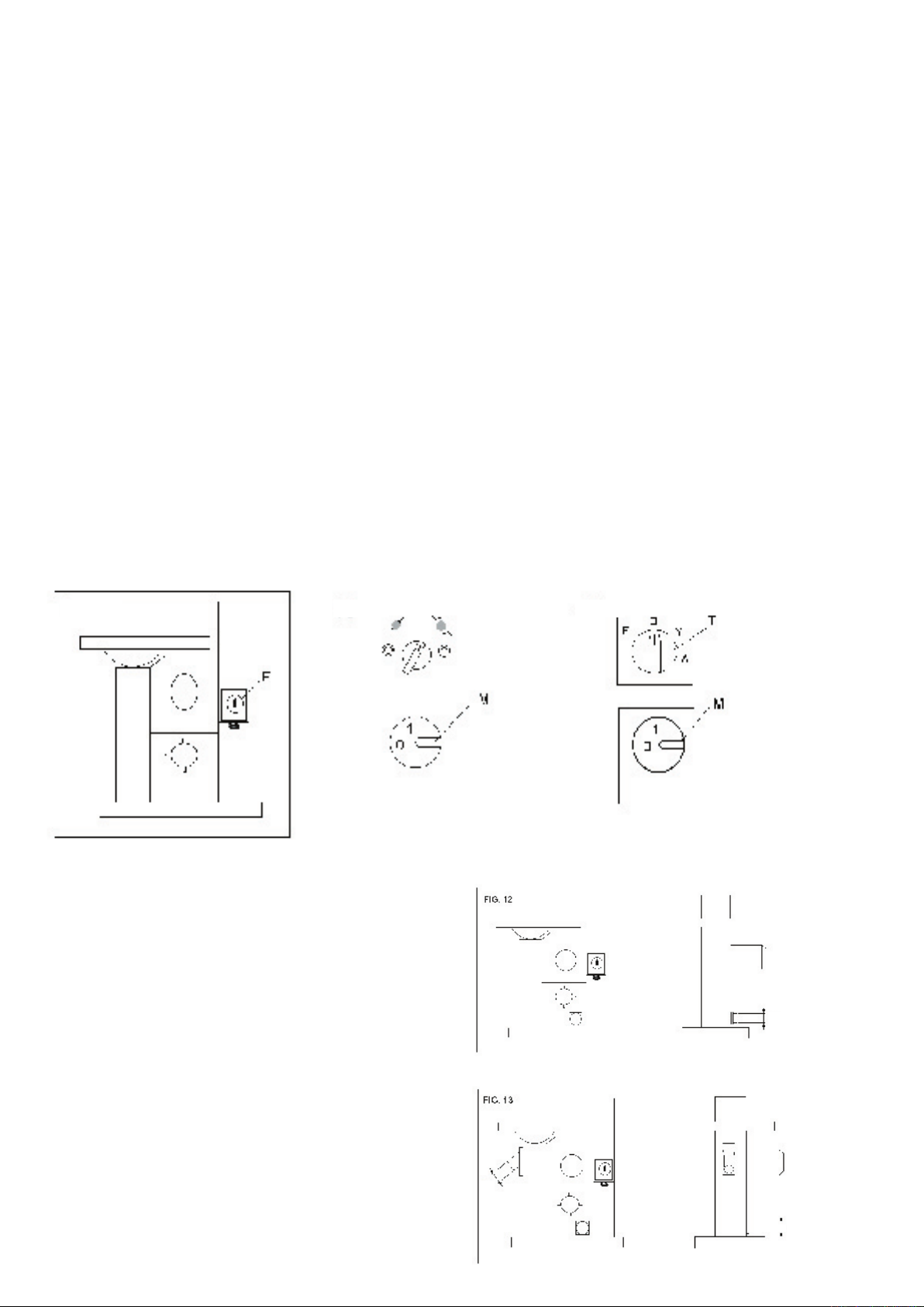
FIG. 9 FIG. 10 FIG. 11
3.4 DUST EXTRACTION
The machine must be connected to
an adequate dust extraction system.
Diameter of the extraction tubes and
connecting positions on the machines are
indicated in FIG. 12 and FIG. 13
Airspeed: The minimum advisable
air speed is 20 mt/sec for wood with
humidity less than 12%. For wood
with an humidity greater than 12% it is
advisable to increase the air speed to
25-28mt/sec.
Capacity: Approx 600mt/h for tube diam.
100mm, 800m /h for tube diam 120mm,
1100mt/h for tube diam 140mm.
.
Model Port Size
352SB L: 120mm
401S L: 120mm
501S L: 120mm
581S L: 120mm
681S L: 120mm
Model Port Size
440R L: 120mm
U: 100mm
L
781S L: 120mm
U: 100mm
U
L
4. Using The Machine
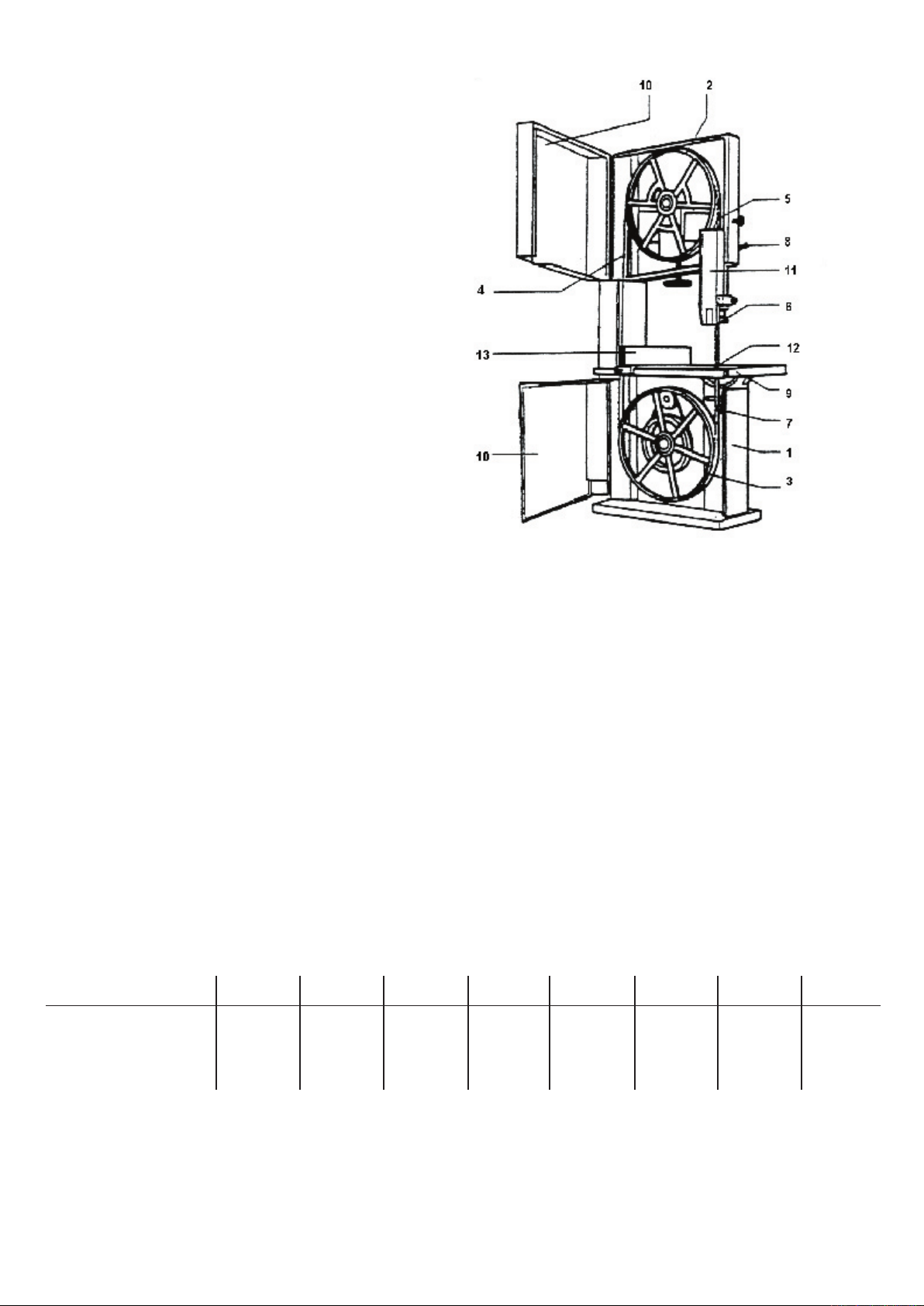
4.1 PRINCIPAL MACHINE PARTS
1 Base
2 Upper bandwheel
3 Lower bandwheel
4 Blade upward portion
5 Blade downward portion
6 Upper blade guide
7 Lower blade guide
8 Blade guide height adjustment
9 Table
10 Bandwheel door guard
11 Adjustable blade guard
12 Table insert
13 Rip fence
ATTENTION!! DISCONNECT THE ELECTRICAL SUPPLY
BEFORE EVERY ADJUSTMENT
ATTENTION!! IN CASES OF BLADE BREAKAGE WAIT UNTIL
THE UPPER
BEFORE OPENING THE DOOR.
BANDWHEEL HAS COMPLETELY STOPPED
4.2 CHOICE AND MAINTENANCE OF BLADES
The table below defines the blade length and maximum width, depending on the type of the machine.
Selection of width and type of tooth depends upon the materials to be cut and the type of operation, narrow blades are suitable for
cutting curved lines, profiles etc.., wide blades are best for straight cutting.
It is advisable to use finer teeth for hard woods or thin material and coarser teeth for softwoods or deep material. In every case, the
distance between each tooth should be sufficient to clear the sawdust produced during the cutting operation. If the clearance is not
correct this can cause overheating and jamming of the blade, causing subsequent breakage .
Do not use flawed or deformed blades.
It is highly recommended that the blade be changed regularly. Use a specialised saw doctor for welding, sharpening and re-setting
blades. The use of high quality blades is also recommended
Causes of blade breakage:
• Excessive blade thickness in relation to the bandwheel size.
• Defective welding
• Incorrect tension, particularly if the blade is over tensioned the tension spring no longer fulfils its function
• Overloading the blade caused by using a badly ground or badly set blade, or by not slackening the tension
• After use it is recommended to slacken the tension, especially overnight, (placing a visible notice of this operation on the machine).
Re-tension before next next operation.
• Misalignment of the bandwheels due to unauthorized intervention of the regulating screws of the lower bandwheel.
• Irregularity of bandwheels surface, e.g an accumulation of sawdust whilst cutting resinous materials.
352SB* 401S 440R 501S 581S 681S 781S
Blade Length (Min) 3560mm / 141” 3850 4060mm / 160” 4170mm / 165” 4610mm / 182” 5100mm / 201” 5750mm / 227”
Blade Length (Max) 3640mm / 143” 4170mm / 164” 4280mm / 168” 4680mm / 184” 5150mm / 203” 5820mm / 229”
Blade Width mm 6 - 30 6 - 30 6 - 50 6 - 35 6 - 35 6 - 40 6 - 45
401E
Blade Length 3850mm
Blade Width mm 6 - 30
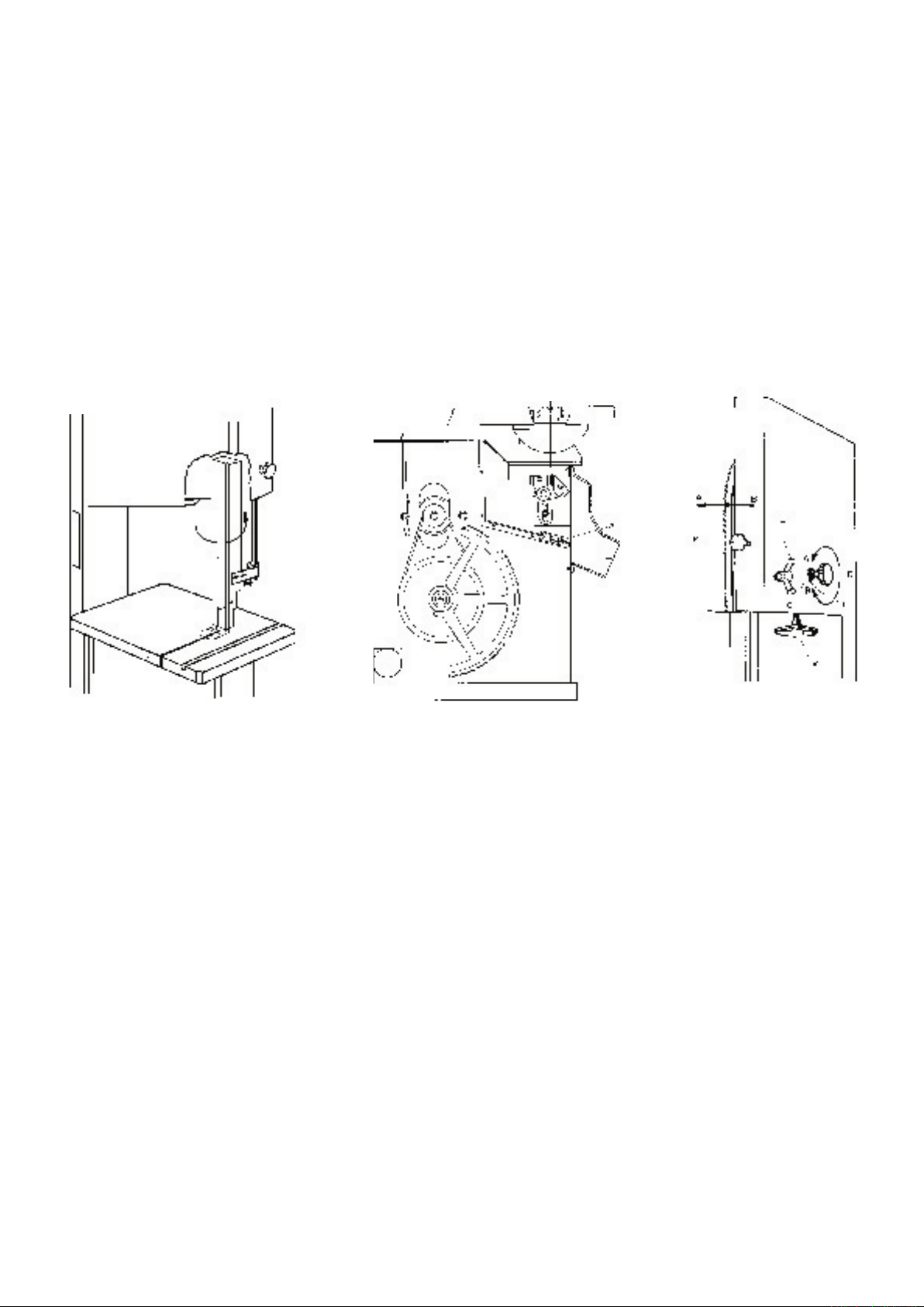
4.3 BLADE MOUNTING AND ADJUSTMENT
When mounting the blade it is necessary to release the motor brake that prevents manual rotation of bandwheels. To release the
brake, while machine is stopped, move the brake release selector (FIG. 10 & FIG.11 section 3.3) turning it toward the release
symbol.
On Star-Delta starter machine turn switch
To mount blade first open the panel of the top blade guard (FIG. 15) and remove, (if fitted) the table insert (FIG. 16). Place the blade
onto the bandwheel checking the teeth are in a correct position, and tighten the tension using the handwheel “
correct tension value is indicated on the dynamometer fitted to the machine, the indicated value corresponds to the width of the blade.
(e.g. for blade width 25 mm tighten until no. 25 appears on the indicator).
Turn the bandwheels manually, checking that the blade does not interfere with any fixed parts and that the blade is placed correctly on
the bandwheels. The points of the teeth should slightly protrude over the edge of the bandwheels. To adjust the blade position on the
bandwheels slacken the locking lever “
will move inwards, anticlockwise the blade move further out; a quarter of a turn is sufficient to produce a noticable displacement. After
several roations of the wheel and the blade is positioned correctly tighten the locking lever.
At this point close the movable blade guide, re-position the lower wooden insert, (if fitted), and close the bandwheel access doors.
Move the brake selector back to the locking position .
IMPORTANT NOTE :
After use we recommend slackening the blade tension, and to display a visible sign on the machine advising of this procedure.
FIG. 15 FIG. 16 FIG. 17
“M” to position “0” then turn switch “T” to position “F” (FIG. 11).
V” , FIG. 17. The
C”, FIG. 17, and then move the knob “D”, FIG. 17: moving it in a clockwise direction the blade
4.4 SETTING THE BLADE GUIDES
CERAMIC GUIDES (STANDARD ON ALL MACHINES)
A revolutionary blade guide system (several patents pending) that is designed to give
many years of superior high quality band sawing. Unlike other blade guide systems
which support the sides of the blade and then support the rear of the blade, either
above or below these sides guides. The ceramic guides supports the blade on the
sides above and below the rear blade guide, thus eliminating all blade twist, the
ceramic guide gives the blade unsurpassed stability.
Ceramic guide blocks are used instead of conventional materials for both side and
rear thrust support. This enables the guides to run tight against the blade on all sides
without heat build up giving a blade stability that has never been achievable before.

4.5 TABLE INSERT FOR DUST EXTRACTION
The machines are equipped with a
removable plastic insert on the worktable, FIG.20, pos “B”, the relieved holes
of the insert improve dust extraction.
By adjusting the 4 screws at the bottom
of the opening of the work-table it is
possible to change the height of the
insert in relation to the work surface.
Models with fly-wheels up to 600 mm
diameter have one extraction outlet,
models with larger diameters have a
second outlet fitted on the base , under
the work-table ( FIG. 20, pos “
It is recommended that the insert “ A
“ be replaced when the blade cutting
clearance widens, this will maintain
maximum efficiency of dust extraction.
L” ).
4.6 CUTTING DIRECTION
AND PARALLELISM
If the cut is not perfectly parallel when
using the parallel rip fence the possible
causes are:
• Incorrect grinding and setting
of the blade
• Insufficient blade tension
• Incorrect setting of the parallel rip fence
in respect of the blade; to adjust the
parallelism of the guide, slacken, without
removing, the 2 screws “
adjust the guide position and re-tighten,
firmly, the 2 screws
R “, FIG. 20,
FIG. 20
4.7 TILTING THE WORK TABLE
The table can be tilted to a maximum of 20°
To incline it, loosen off the locking ratchet handle FIG. 21
position B. Use the box spanner provided to turn rack and pinion
mechanism FIG. 21 position A. Turn until table is at required angle.
FIG. 21

5. Safety Advice
a) Machine out of order
Before making any adjustments or repairs to the machine, disconnect from the electrical supply.
If any faults are suspected, disconnect the electrical supply and put a visible notice on the machine.
b) Before operating
• Keep the surrounding floor space clean;
• Wear suitable clothing, not loose garments;
• Check that the blade is sharp, correctly tensioned, the correct width, and correctly positioned on the flywheels;
• Use support stands for long or wide material
• Use a dust extractor.
c) During operation
Never clean the table with hands, use a brush or a piece of wood.
In case of an emergency such as blade breakage or other emergency do not attempt to intervene before the bandwheels have
completely stopped.
When the has stopped, lower the upper blade guides to the level of the table, loosen the blade and leave a sign advising of this
operation. REMOVE THE ELECTRICAL CONNECTION PLUG.
d) During maintenance
• Place the machine out of order as indicated above;
• Use gloves to handle the blade;
• Periodically check the electrical grounding of the machine.
5.1 SAFETY DEVICES AND GUARDS
The upward portion of the blade is fully protected inside the machine column.
The down ward portion of the blade is protected by a fixed guard, integral with the blade-guide which is adjustable for height
depending on the thickness of material to be cut.
5.2 FACE CUTTING
Use a square for safe guiding of the work during face cutting FIG. 5.1
CUTTING SHORT PIECES FIG. 5.2
Use pushing devices for cutting of short pieces.
The pushing device type A is recommended for narrow pieces.
FIG. 5.1
FIG. 5.2

5.3 CUTTING OF ROUND PIECES FIG. 5.3
Use a wedge rest to prevent rotation of round parts during cutting.
5.4 WEDGE CUTTING FIG. 5.4
Pushing device for wedge cutting
FIG. 5.3
5.5 CUTTING OF WEDGE-SHAPED LENGTHS FIG. 5.6
Equipment for cutting wedge-shaped lengths.
FIG. 5.4
FIG. 5.5

6. Braking System
The machines are equipped with an electro-magnetic brake that
ensure stopping all moving parts within 10 seconds,
The brake pads of the braking system are subject to wear, it
is recommended that they are checked regularly and replaced
when necessary, to maintain the braking time within regulations
fixed by the norms.
6.1 MAINTENANCE AND ADJUSTMENT OF
THE BRAKING SYSTEM
REPLACING THE BRAKE LININGS
Remove the fan cover (
(31), pull out thecooling and braking fan (34) On the mobile
anchor (
off and, with clean hands, glue the new one on. To re-assembly
the parts, please follow directions in reversed order and type of
operations.
BRAKE UNIT REPLACEMENT
Take the fan cover (
pull out the cooling and braking fan (
and the thrust spring (
rectifier diode by disconnecting the cables (the diode can be
found either in position (
Unscrew the 3 allen screws (
repeat the operations in reverse to fit the other parts.
ADJUSTMENT OF THE BRAKING AIR-GAP
The machine will stop between 6 and 10 seconds maximum. By
turning the self locking nut of the brake control (
to vary the braking time from 6 to 10 seconds. It is extremely
important that after this operation a gap of 0.5 mm remains
between the mobile anchor and the brake unit. The air gap is the
distance between the mobile anchor and the brake unit.
MANUAL OPERATION TO RELEASE THE BRAKE
Unscrew the self locking nut (
away from the mobile anchor (
air gap. This allen screw also allows to check the air gap back to
the original distance after the wearing out of the brake linings.
28) of the brake you will find the lining. Pull the old lining
40) and unscrew the self-locking nut
40) off and unscrew the self locking nut (31)
34), the thrust linings (24)
27). At this point, you should isolate the
44) or in the terminal box position 18).
23), change the brake unit and
31) it is possible
31) until the cast iron fan moves
28) beyond the widest possible

7. Maintenance
BEFORE ANY INTERVENTION ALWAYS DISCONNECT
THE ELECTRICAL SUPPLY!
Periodically check that all screws are tightly fastened and the
condition of the various guards
V BELTS
After the first few hours of operation it is necessary to check
that the tension of the belts is correct,as they tend to stretch.
To control the tension of the belts push the mid-point of the
belt applying 3-4 Kg of pressure, the displacement should not
exceed 5-6 mm. To adjust the blade tension loosen the nuts A,
FIG. 23, and tighten the nut
tension, tighten the nuts .
It is recommended that the correct blade tension is maintained
as loose belts reduce the motor power and can increase the
braking time. Belts that are too tight can cause the belts to
become hot .
TO CHANGE THE BELTS
Slacken the tension as described above, remove the screw “
FIG. 22, loosen the screws “
pull-out the bandwheel and shaft, repeat the operations in
reverse to re-assemble.
IMPORTANT: loosen only the 2 screws indicated so as not to
interfere with the alignment of the fly-wheel.
DISMANTLING THE UPPER FLY-WHEEL
Remove the screw “
from their positions.
REPLACEMENT OF RUBBER COVERING OF
THE FLY-WHEELS
It is recommended that this be carried out by a competent
specialist or the manufacturer, this is because the rubber
covering is not only glued onto the fly-wheel, but also ground in
a crown form. It is strongly advised not to grind and shape the
rubber directly on the machine using gouges, files or abrasives.
CLEANING AND LUBRICATING
Periodically clean the inside of the machine with the aid of a
dust extractor for any saw-dust deposits, remove any resinous
deposits from the fly-wheels surface. The fly-wheel bearings
do not require any greasing. It is not necessary to lubricate any
part or component of the machine as the sawdust circulating
within will adhere to any oiled or greased surface jeopardizing
the sliding of moving parts such as the shaft of the blade guide
adjustment and the slide of the tensioning group.
Frequently control the cleanliness of the rubber surfaces on the
fly-wheels, particularly in cases of cutting resinous materials or
chip-board. Clean the surfaces, while machine is not in motion ,
of any resinous deposits taking care do not damage the surface.
E”,FIG.24 and remove fly-wheel and shaft
D, FIG. 23, this will increase the
B”,
A”,
FIG. 23
FIG. 24
FIG. 22

8. Trouble Shooting
THE MOTOR DOES NOT START
• Check that the fly-wheel doors are correctly closed , otherwise the safety microswitch will not allow operation
• Check that the emergency button, when fitted, is released.
• If the “
position, or,when the star delta is fitted,check that the knob of the star delta starter is in “
• The motor lacks electrical power: consult an electrician.
THE MACHINE DOES NOT WORK EFFICIENTLY DURING OPERATION
• Incorrect connection of the motor: consult an electrician
• Loose drive belts: follow the tightening procedure
DOES NOT CUT STRAIGHT
• Check the sharpness and setting of the blade
• Check the alignment of the rip fence
THE BLADE HAS CRACKS AT THE BASE OF THE TEETH
• Incorrect sharpening and consequent overheating, othervise incorrect setting of the teeth
• Incorrect blade thickness in relation to bandwheels diameter
• The bandwheel tyres are damaged or have incrustation deposits
• Badly aligned bandwheels: requires the intervention of a qualified technician
THE BLADE IS CRACKED AT THE BACK
• Excessive feed during cutting
• Imperfect weld alignment: eliminate badly welded part and repeat the weld
• The rear thruster of the blade guide is damaged
ON“ button of the magneto thermal switch does not lock-in, check that the selector to release the brake is in the correct
O” position.
THE BLADE BREAKS AT THE WELD :
• Overheating of the blade during welding: remove the weak area and repeat the welding
• Cooling down the weld too quickly after welding, proceed as above
THE MACHINE STOPS WITH THE BLADE JAMMED INTO THE WORKPIECE
• Stop the motor and release the brake, widen the cut using a wedge to aid removing the workpiece, after this operation check the
blade and its position on the bandwheels before recommencing
OTHER PROBLEMS
• The blade moves backwards and forwards: weld misaligned
• The blade slips back at the beginning of cut: blade not sharpened or blade incorrect for material in work or there is a defect on
the crown of the bandwheel surface.
9. Ordering Spare Parts
WHEN ORDERING SPARE PARTS SPECIFY:
Machine Model
Serial number
Part number required, taken from the enlarged machine designs on the following pages
Quantity required
EXAMPLE: TO ORDER LOWER FLY WHEEL FOR 781S
Model: 781S
Registration number: xyxyxyy
Part number: 95
Quantity: 1 piece
9.1 DRIVE BELTS & BALL BEARING PART NUMBERS
Model V-Belt Ball Bearings
352SB 3V335 6205 2RS
401S 3V335 6205 2RS
440R 3V755 x2 62062 RS
501S 3V450 6205 2RS
581S 3V400 6206 2RS
681S 3V450 6206 2RS
781S 3V530 6306 2RS
941S 3VX600 x2 6308 2RS

10. Diagrams & Components


Woodworking Machinery
Bandsaws
Band Re-saws
Dust extractors
Panel saws
Planer thicknessers
Planers
Thicknessers
Circular Saws
Spindle Moulders
Universals
Startrite Machines
Unit B, Ireland Industrial Est.
Adelphi Way, Staveley
Chesterfield
England S43 3LS
T: 0870 770 1777
F: 0870 770 1888
E: info@startrite.co.uk
W: www.startrite.co.uk
 Loading...