


Original Instruction Manual
Version 2.2
May 2012
Woodworking Machines & Accessories
Telephone: 01246 561 520
Fax: 01246 561 537
Startrite
Unit B, Adelphi Way
Staveley S43 3LS
Email: sales@recordpower.co.uk
www.startrite.co.uk
352E & 502E
Industrial
Bandsaws
IMPORTANT
For your safety read instructions carefully before
assembling or using this product. Save this
manual for future reference.
HEALTH AND SAFETY GUIDELINES
Always follow the instructions provided with the manual. Always wear safety glasses when using woodworking
equipment. Always disconnect the power before adjusting any equipment. Failure to observe proper safety
procedures and guidelines can result in serious injury.
WARNING: Do not allow familiarity (gained from frequent use of your machine and accessories) to become
commonplace. Always remember that a careless fraction of a second is sufficient to inflict severe injury.
Always wear safety glasses when
using woodworking equipment.
Always read the instructions
provided before using
woodworking equipment.

Contents
Page 3 Startrite Guarantee
Page 4 1. General Information
2. Machine Description
Page 5 3. Installation
Page 7 4. Health & Safety Guidance
Page 8 5. Additional Health & Safety Information for Bandsaws
Page 9 6. Using the Machines
Page 14 7. Safety Advice
Page 16 8. Maintenance
Page 17 9. Troubleshooting
Page 18 10. Diagrams & Parts Lists
Page 31 EU Declaration of Conformity

2 3
Startrite Guarantee
1. INTRODUCTION
1.1 We supply machinery through a network of dealers and authorised
distributors and you should be aware that your contract of sale is with the
retailer from whom you purchased this product.
1.2 If you are not satisfied with this product you should in the first instance
approach the retailer from whom you purchased it.
1.3 Customers have statutory rights to protect them and information on
this can be found at the Citizens Advice Bureau or on such web-sites as
those operated by the DTI (http://www.dti.gov.uk)
1.4 Returning your guarantee card will speed up the claims procedure
and can be very helpful as a proof of purchase should the initial receipt be
mislaid or damaged. We recommend that this is returned as close to your
original purchase date as possible.
1.5 Correct installation, set-up, adjustment and routine maintenance of
the machine are the responsibility of the end-user and problems arising
from incorrect set-up, adjustment or maintenance are not covered by the
terms of this guarantee. However support is available in the first instance
from the retailer who supplied you and free technical support is available
from Startrite on 01246 561 520 during office hours and from an extensive
knowledge base on our website www.startrite.co.uk. We also recommend
those users who have not had suitable training in safe use of machinery
should seek such training locally before using or attempting to set up and
adjust any machinery (please contact your retailer for recommendations in
your local area).
2. GUARANTEE
2.1 In addition to the above Startrite guarantees that for a period of 1 year
from the date of purchase the components of this product will be free from
defects caused by faulty construction or manufacture.
2.2 During this period Startrite will repair or replace free of charge any
parts which are proved to be faulty in accordance with paragraph 2.1 above
provided that:
2.2.1 You follow the claims procedure set out below;
2.2.2 We are given a reasonable opportunity after receiving notice of the
claim of examining the product.
2.2.3 If asked to do so by us you return the product or faulty part to
Startrite's premises or other approved premises such as those of the
supplying dealer, for the examination to take place.
2.2.4 The fault in question is not caused by accidental damage, fair
wear and tear, wilful damage, negligence on your part, incorrect electrical
connection, unapproved modification, abnormal working conditions, failure
to follow our instructions, misuse, or alteration or repair of the product
without our approval.
2.2.5 This product has been purchased by you and not used for hire
purposes;
2.2.6 This Guarantee extends to the cost of carriage incurred by you
returning the product or faulty part to Startrite as long as it is demonstrated
that the defect falls within the terms of this Guarantee and you follow the
claims procedure as outlined below;
3. CLAIMS PROCEDURE
3.1 In the first instance please contact the retailer who supplied the
product to you. In our experience many initial problems with machines that
are thought to be due to faulty parts are actually solved by correct setting
up or adjustment of the machines. A good dealer should be able to resolve
the majority of these issues much more quickly than processing a claim
under the guarantee.
3.2 If the dealer who supplied the product to you has been unable to
satisfy your query, any claim made under this Guarantee should be made
directly to Startrite at the address set out at the foot of this Guarantee. The
claim itself should be made in a letter setting out the date and place of
purchase, and giving a brief explanation of the problem which has led to
the claim. This letter should then be sent with proof of the purchase date
(preferably a receipt) to Startrite. If you include a phone number or email
address this will help to speed up your claim.
3.3 PLEASE NOTE that it is essential that the letter of claim reaches the
address below on the last day of this Guarantee at the latest. Late claims
will not be considered.
3.4 We will contact you once we have received your initial written claim.
If it is necessary to return the item, in most cases but subject always
to clause 2.2.5, we will arrange for collection or will provide freepost
information to enable return depending on the weight and size of the
product or component concerned. If the product is to be returned to us, we
will agree with you in advance a Returns Number, to speed tracking of the
claim and ensure the most appropriate method of return to you is used.
4. NOTICE
This Guarantee applies to all goods purchased from an authorised retailer of
Startrite within the United Kingdom of Great Britain and Northern Ireland.
This Guarantee does not confer any rights other than those expressly set out
above and does not cover any claims for consequential loss or damage. This
Guarantee is offered as an extra benefit and does not affect your statutory
rights as a consumer. Additional written copies of this Guarantee can be
obtained by writing to the address below. Please include a stamped and self
addressed envelope for each copy of the Guarantee requested.
Startrite Machines
Unit B, Adelphi Way
Ireland Industrial Estate
Staveley, Chesterfield
S43 3LS

1. General Information
1.1 FOREWORD
This manual must be read and understood before operating the machine. This will provide a better working knowledge of the machine, for increased safety
and to obtain the best results.
2. Machine Description
2.1 MACHINE IDENTIFICATION
There is a specification label fixed to the machine, containing the manufacturer's data, year of construction,
serial number and blade data.
2.2 TECHNICAL SPECIFICATION
SPECIFICATION 502E 502E 352E 352E
(Phase) (Single Phase) (Three Phase) (Single Phase) (Three Phase)
Throat depth mm 465 465 345 345
Blade Speed m/min 1000 1000 1000 1000
Motor Power output W 2450 2300 2000 1900
Cutting Depth (mm) 335 335 250 250
Table Tilt 0-20º 0-20º 0-20º 0-20º 0-20º
Table Height mm 950 950 1040 1040
Blade Length mm 3810 3810 2845 2845
Blade Width mm 10-35 10-35 6-25 6-25
Nett Weight kg 200 200 125 125
Size mm W990 x D680 x H1970 W990 x D680 x H1970 W820 x D660 x H1835 W820 x D660 x H1835
Power Supply 230V / 50Hz 400V / 50Hz 230V / 50Hz 400V / 50Hz
Full Load Current A 10.62 4.68 9.41 4.16
Max Short Circuit Current A 1000 1000 1000 1000
2.3 RECOMMENDED PROTECTIVE CLOTHING
• Gloves for moving work material and when carrying out the blade changes;
• Non-slip shoes;
• Protective eye glasses.
2.4 NOISE EMISSION
The measurements of noise, in the working position and during operation, were carried out under the standard ISO 7960 annex "J":
Instantaneous acoustic pressure: (Constant K4 dB measured in accordance with EN150 3746: 1995)
Sound power level (no load) <90 dB(A)
Sound power level (load) <100 dB(A)
Sound Pressure level (no load) <80 dB(A)
Sound Pressure level (load) <90 dB(A)
The figures quoted are emission levels and are not necessarily safe working levels. Whilst there is a correlation between the emission and exposure
levels, this cannot be used reliably to determine whether or not further precautions are required. Factors that influence the actual level of exposure of the
workforce include the characteristics of the work room and the other sources of noise etc. i.e. the number of machines and other adjacent processes. Also
the permissible exposure level can vary from country to country. This information, however, will enable the user of the machine to make a better evaluation
of the hazard and risk.

2.5 PRESCRIBED USE OF THE MACHINE
The machine was designed for cutting solid wood, wood derivatives, materials similar to cork, hard rubber and hard plastic materials using suitable blades.
THESE MACHINES MUST NOT BE USED TO CUT OTHER MATERIALS
THESE MACHINES MUST NOT BE USED TO CUT METALS
2.6 HAZARDS
ATTENTION Bandsaws still present risks that cannot be eliminated by the manufacturer. Therefore the user must be aware that wood working machines are
dangerous if not used with care and all safety precautions adhered to.
3. Installation
3.1 LIFTING
The machine can be lifted using a fork-lift truck,
placing the forks under the feet or by using a
“SLING”, as shown, with a lifting capability of
2000 Kg.
3.2 POSITIONING THE MACHINE
For a correct and rational organisation of the work area:
• Install the machine in an area that will not amplify vibration or noise.
• Ensure that the work area has adequately lighting.
• When placed between other machinery there should be a space of at least 80 cm. It is necessary to anticipate sufficient space for cutting long work
pieces traversely and for the fitting of rollers or other types of support in front and at the rear of the table.
There are four holes for fixing the machine to the floor. When fixing to the floor it is recommended not to over tighten the fixtures to avoid increasing
vibration. It is also advisable to place anti-vibration materials between the floor and the base of the machine.
NOTE: Due to the height of the machine, the centre of gravity will also be high causing the machine to be unstable or top heavy. The machine, where
possible should always be fixed directly to a solid floor using appropriate fixings for the type of floor.
Extra care should be taken when moving the machine to ensure that it cannot fall. Always ensure that machine is fully supported and operators stand well
clear whilst the machine is moved.
Sling 2000kg
Timber
3.3 DUST EXTRACTION
The machine must be connected to an
adequate dust extraction system. Diameter of
the extraction tubes and connecting positions
on the machines are indicated.
1, Necessary Airflow = 460m3/h
2, Pressure drop at each dust extraction
connection outlet at the conveying air
velocity = 530Pa
3, Recommended conveying air velocity = 20m/s
B
A
Model Port Size
352E A:32mm B:100mm
502E A:100mm B:100mm
4 5
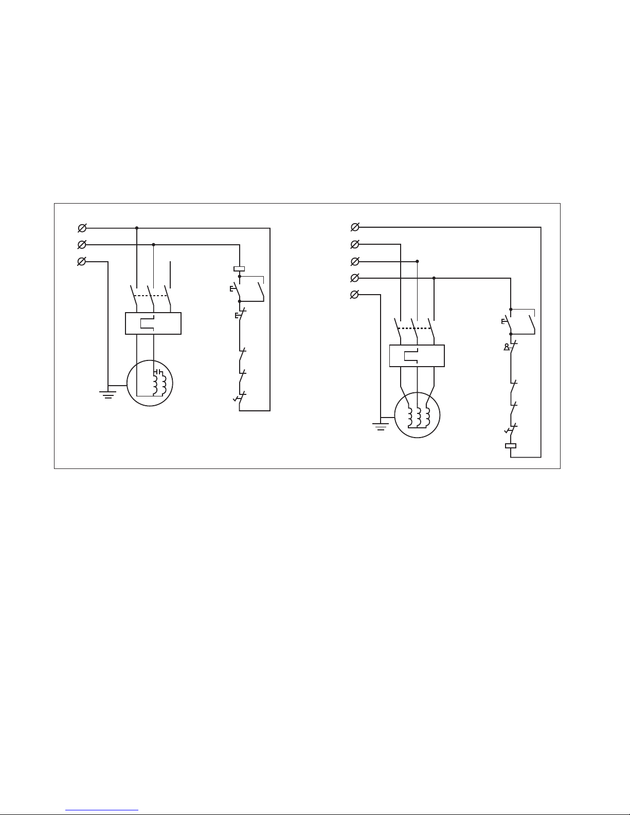
3.4 ELECTRICAL CONNECTION - START UP
Electrical installation should be carried out by competent, qualified personnel.
The mains connection should be made using the terminal box.
Ensure that the mains supply corresponds with that of the machine, use cables of a section suitable for the power of the motor. For a supply tension of 400
V the minimum section recommended is 2.5 mm, including the earth wire.
For a mains supply of 230 V or a power rating greater than 15 A it will be necessary to increase the section of the connecting cables.
Connect the phase wires to the terminals R- S - T (L1 - L2 - L3) and the earth wire to the earth terminal.
On initial start-up check the direction of rotation, if it is incorrect then invert the two phase wires (for machines with 3 phase supply). Direction of rotation
of machines with single-phase supply is pre-determined during production .
On completion of the installation check that the terminal box is closed correctly and that the plug points are locked.
Starting the machine :
352E & 502E - Single Phase
352E & 502E - Three Phase
L1
L2
L3
PE
KM
FR
KM
KM
SB1
SQ1
SQ2
SF
N
SA
L
N
PE
KM
FR
KM
KM
SB1
SB2
SQ1
SQ2
SF
T1: Transformer
SQ1: Sefety switch
SQ2: Sefety switch
SF: Foot switch
SB1: Stop button
SB2: Start button
KM: Contactor
FR: Overload contactor
Q1 & Q2: Circuit breaker

6 7
THE MACHINE SHALL BE DISCONNECTED FROM THE SUPPLY
BEFORE MAINTENANCE.
WARNING: WHEN USING POWER TOOLS, BASIC SAFETY
PRECAUTIONS SHOULD ALWAYS BE FOLLOWED TO REDUCE
THE RISK OF FIRE, ELECTRIC SHOCK AND PERSONAL INJURY,
INCLUDING THE FOLLOWING.
READ ALL THESE INSTRUCTIONS BEFORE ATTEMPTING TO
OPERATE THIS MACHINE. SAVE THIS INSTRUCTION MANUAL FOR
FUTURE REFERENCE.
1. Keep work area clear
- Cluttered areas and benches invite injuries.
2. Consider work area environment
- Do not expose tools to rain.
- Do not use tools in damp or wet locations.
- Keep work area well lit.
- Do not use tools in the presence of flammable liquids of gases.
3. Guard against electric shock
- Avoid body contact with earthed or grounded surfaces.
4. Keep other persons away
- Do not let persons, especially children, not involved in the work
touch the tool or the extension cord and keep them away from
the work area.
5. Store idle tools
- When not in use, tools should be stored in a dry locked up
place, out of reach of children.
6. Do not force the tool
- It will do the job better and safer at the rate for which it was intended.
7. Use the right tool
- Do not force small tools to do the job of a heavy duty tool.
- Do not use tools for purposes not intended : for example do
not use circular saws to cut tree limbs or legs.
8. Dress properly
- Do not wear loose clothing or jewellery, they can be caught in
moving parts.
- Non-skid footwear is recommended when working outdoors.
- Wear protective hair covering to contain long hair.
9. Use protective equipment
- Use safety glasses.
- Use face or dust mask if cutting operations create dust.
10. Connect dust extraction equipment
- If device are provided for the connection of dust extraction and
collecting equipment, ensure these are connected and properly used.
11. Do not abuse the cord
- Never yank the cord to disconnect it from the socket.
- Keep the cord away from heat, oil and sharp edges.
12. Secure work
- Where possible use clamps or a vice to hold the work.
- It is safer than using your hand.
13. Do not overreach
- Keep proper footing and balance at all times.
14. Maintain tools with care
- Keep cutting tools sharp and clean for better and safer
performance.
- Follow instructions for lubricating and changing accessories.
- Inspect tool cords periodically and if damaged have them
repaired by an authorized service facility.
- Inspect extension cords periodically and replace if damaged.
- Keep handles dry, clean and free from oil and grease.
15. Disconnect tools
- When not in use, before servicing and when changing
accessories such as blades, bits and cutters, disconnect
tools from the power supply.
16. Remove adjusting keys and wrenches
- Form the habit of checking to see that keys and adjusting
wrenches are removed from the tool before turning it on.
17. Avoid unintentional starting
- Ensure switch is in “off” position when plugging in.
18. Use outdoor extension leads
- When the tool is used outdoors, use only extension cords
intended for outdoor use and so marked.
19. Stay alert
- Watch what you are doing, use common sense and do not
operate the tool when you are tired.
20. Check damaged parts
- Before further use of tool, it should be carefully checked to
determine that it will operate properly and perform its
intended function.
- Check for alignment of moving parts, binding of moving
parts, breakage of parts, mounting and any other conditions
that may affect its operation.
- A guard or other part that is damaged should be properly
repaired or placed by an authorized service centre unless
otherwise indicated in this instruction manual.
- Have defectives switches replaced by an authorized
service centre.
- Do not use the tool if the switch does no turn it on and off.
21. Warning
- The use of any accessory or attachment other than one
recommended in this instruction manual may present a-risk
of personal injury.
22. Have your tool repaired by a qualified person
-This electric tool complies with the relevant safety rules. Repairs should
only be carried out by qualified persons using original spare parts,
otherwise this may result in considerable danger to the user.
23. Safety precautions
-Do not use saw bands which are damaged or deformed.
-Replace the table insert when worn.
-Connect band saw to a dust-collecting device when sawing wood.
-Do not operate the machine when the door or guard protecting the
saw band is open.
-Take care that the selection of the saw band and the speed depends
on the material to be cut.
-Do not clean the saw band whilst it is in motion.
-Wear suitable personal protective equipment, when necessary, this
could include:
-Hearing protection to reduce the risk of induced hearing loss.
-Respiratory protection to reduce the risk of inhalation of harmful dust.
-Gloves for handling the saw band and rough material.
24. Safety operation
-When straight cutting against the fence use a push stick.
-During transportation the saw band guard should be fully down and
close to the table.
-When bevel-cutting with the table inclined, place the guide on the
lower part of the table.
-When cutting round timber use a suitable holding device to prevent
twisting of the workpiece.
-Handle and two wheels for lifting and transportation positions have
clearly been indicated on the tool.
-Do not use guarding for handling or transportation.
-Adjust the adjustable guard as close to the workpiece as practicable.
25. Adjust the guard as close as possible to the piece to be cut.
26. For the long workpiece, auxiliary device shall be used for cutting(such
as
roller stand).
27. The store location for push stick.
28. The electrical equipment shall be operated correctly under the load with
the conditions of the nominal supply: 0.9 to 1.1 times of nominal voltage.
29. The electrical equipment shall be capable of operating correctly in
an ambient air temperature between +5°C and +40°C, and the average
ambient air temperature over a period of 24 h shall not exceed +35°C.
30. The electrical equipment shall be capable of operating correctly within a
relative humidity not exceed 90%(20°C).
31. The electrical equipment shall be capable of operating correctly at
altitudes up to 1000m above mean sea level.
32. The mains connection must have maximum 16A fuse.
Eye Protection
The operation of any power tool can result in
foreign objects being thrown into your eyes, which can result in severe eye
damage. Always wear safety glasses or other suitable eye protection. Wear
safety glasses at all times. Everyday glasses only have impact resistant
lenses. They are not safety glasses which give additional lateral protection.
It is also important to wear ear protectors when operating the table saw.
ATTENTION!
Through poor conditions of the electrical MAINS, short voltage drops can
appear when starting the EQUIPMENT. This can influence other equipment
(eg. Blinking of a lamp). If the MAINS-IMPEDANCE Zmax<0.325W (for and
0.420W) such disturbances are not expected. (For the futher information
contact your local supplier).
4. Health and Safety Guidance

SAFETY IS A COMBINATION OF OPERATOR
COMMON SENSE AND ALERTNESS AT ALL TIMES
WHEN THE BANDSAW IS BEING USED.
WARNING: FOR YOUR OWN SAFETY, DO NOT ATTEMPT TO OPERATE
YOUR BANDSAW UNTIL IT IS COMPLETELY ASSEMBLED AND INSTALLED
ACCORDING TO THE INSTRUCTIONS.
SAFE OPERATION
1. The bandsaw should be bolted to the floor where possible.
2. If you are not thoroughly familiar with the operation of bandsaws,
obtain advice from your supervisor, instructor, or other qualified person or
contact your retailer for information on training courses. Do not use this
machine until adequate training has been taken.
3. Never turn the machine ‘ON’ before clearing the table of all objects
(tools, scrap pieces etc.)
4. Ensure that:
(i) the voltage of the machine corresponds to the mains voltage.
(ii) To use an earthed power source (wall socket).
(iii) The cord and plug are in good condition, i.e. not frayed or damaged.
(iv) No saw teeth are missing and the blade is not cracked or split.
Otherwise replace blade.
(v) The blade is properly tensioned and aligned.
5. Never start the machine with the saw blade pressed against the
workpiece.
6. Never apply sideways pressure on the blade as this may cause the blade
to break.
7. Care must be taken when cutting wood with knots, nails or cracks in it
and / or dirt on it, as these can cause the blade to get stuck.
8. Never leave the machine running unattended.
9. Ensure the teeth of the blade are pointing downwards.
10. Do not use saw blades which are damaged or deformed.
11. Replace the table insert when it is worn.
12. When cutting round timber use a suitable device to prevent twisting of
the workpiece. See section 10 Fig. 10.3.
13. DO NOT operate the machine when the door or the blade guard is not
closed.
14. Adjust the guard as close as possible to the workpiece being cut.
15. Ensure the selection of the saw blade and speed are suitable for the
material to be cut. For most wood cutting applications the fastest of the
two speeds should be used. See section 8.
16. If the mains lead is damaged, it must only be replaced by a qualified
electrician.
17. Never use a long extension cable.
18. WARNING LABELS – It is important that labels bearing Health & Safety
Warnings are not removed or painted over. New labels are available from
Customer Services.
19. MECHANICAL SAFETY – The security of all clamps and work holding
devices should be checked before switching on.
20. WOOD DUST – The fine particles of dust produced in cutting operations
are a potential health risk. Some imported hardwoods do give off highly
irritant dust which causes a burning sensation. We strongly recommend
the use of a dust collector and dust mask/visor. Our Customer Services
Department will be happy to advise you on the correct unit for your needs.
21. Recommended protective clothing:
(i) Gloves for moving work material and when carrying out the blade
changes;
(ii) Non-slip shoes;
(iii) Protective eye glasses.
22. This machine falls under the scope of the ‘Health & Safety at Work
etc. Act 1974’, and the ‘Provision & Use of Work Equipment Regulations
1998’. We recommend that you study and follow these regulations. Further
guidance can be found in the Safe Use of Narrow Bandsaws and the Safe
Use of Woodworking Machinery code of practice booklet (L114) published
by Health & Safety Executive and available by visiting http://www.hse.gov.
uk/pubns/wis31.htm.
For further help on any of the above matters please contact our Customer
Services Department at :Tel: 01246 561 520 Fax:
01246 561 537
WARNING: Do not allow familiarity (gained from frequent use of your
machine) to cause complacency. Always remember that a careless fraction
of a second is sufficient to inflict severe injury.
NOISE EMISSION
The measurements of noise, in the working position and during operation,
were carried out under the standard ISO 7960 annex "J":
Instantaneous acoustic pressure <130.0 dB
The value of the noise level indicated is an emission level and doesn’t
necessarily represent safe working levels.
Although there is a relationship between emission levels and exposure
levels, it isn't precise enough to use in a way to determine whether it
is necessary, or not, to implement further precautions. The factors that
determine the true exposure level to operators are: the amount of exposure
time, the characteristics of the working environment, other sources of dust
and noise etc..
The permitted exposure level limits vary from country to country. this
information allows the machine user to better evaluate the dangers and
risks.
PRESCRIBED USE OF THE MACHINE
The machine was designed for cutting solid wood, wood derivates,
materials similar to cork, hard rubber and hard plastic materials using
suitable blades.
Consult Startrite on Tel:01246 561 520 for advice on the most suitable
blade selection. See section 4.2.
THESE MACHINES MUST NOT BE USED TO CUT OTHER MATERIALS
THESE MACHINES MUST NOT BE USED TO CUT METALS.
ATTENTION Bandsaws still present risks that cannot be
eliminated by the manufacturer. Therefore the user must be
aware that wood working machines are dangerous if not used
with care and all safety precautions adhered to.
We recommend you to study the information given in HSE
document: “Safety in the use of narrow bandsaws”
5. Additional Safety Instructions For Bandsaws
Blade Length
Blade Width mm
602E
4230mm
10 - 35
502E
3810mm
10-35
352E
2845mm
6-25
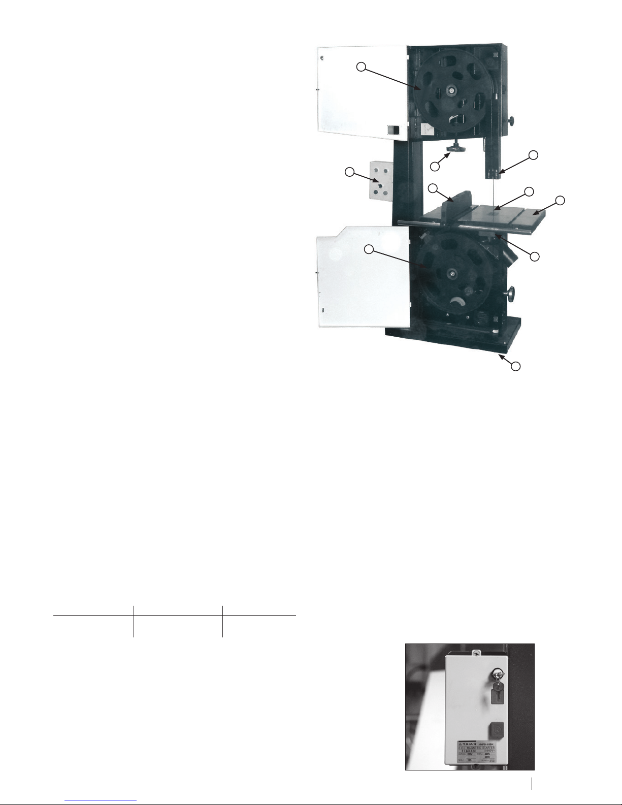
6. Using The Machine
6.1 PRINCIPAL MACHINE PARTS
1 Base
2 Upper band wheel
3 Lower band wheel
4 Switch
5 Blade tension wheel
6 Upper blade guide
7 Lower blade guide
8 Table
9 Rip fence
10 Table insert
ATTENTION!! DISCONNECT THE ELECTRICAL SUPPLY
BEFORE EVERY ADJUSTMENT
ATTENTION!! IN CASES OF BLADE BREAKAGE WAIT UNTIL
THE UPPER BAND WHEEL HAS COMPLETELY STOPPED
BEFORE OPENING THE DOOR.
6.2 CHOICE AND MAINTENANCE OF BLADES
The table below defines the blade length and maximum width, depending on the type of the machine.
Selection of width and type of tooth depends upon the materials to be cut and the type of operation, narrow blades are suitable for cutting curved lines,
profiles etc and wide blades are best for straight cutting.
It is advisable to use finer teeth for hard woods or thin material and coarser teeth for softwoods or deep material. In every case, the distance between
each tooth should be sufficient to clear the sawdust produced during the cutting operation. If the clearance is not correct this can cause overheating and
jamming of the blade, causing subsequent breakage.
Do not use flawed or deformed blades.
It is highly recommended that the blade be changed regularly. Use a specialised saw doctor for welding, sharpening and re-setting blades. The use of high
quality blades is also recommended.
Causes of blade breakage:
• Excessive blade thickness in relation to the band wheel size.
• Defective welding
• Incorrect tension, particularly if the blade is over tensioned the tension spring no longer fulfils its function
• Overloading the blade caused by using a badly ground or badly set blade, or by not slackening the tension
• After use it is recommended to slacken the tension, especially overnight, (placing a visible notice of this operation on the machine). Re-tension before
next operation.
• Misalignment of the bandwheels due to unauthorized intervention of the regulating screws of the lower band wheel.
• Irregularity of bandwheels surface, e.g an accumulation of sawdust whilst cutting resinous materials.
502E 352E
Blade Length 3810mm 2845mm
Blade Width mm 10 - 35 6 - 25
6.3 STARTING THE MACHINE
Before attempting to start the machine, ensure the kickswitch is reset (i.e. pulled forward). For extra
safety a keyswitch is fitted to the control box (Fig 6.1) and must be set to the on position, with the key
vertical, The green 'on' switch can then be engaged.
2
4
5
9
6
10
8
7
1
3
FIG. 6.1
8 9

6.4 FITTING THE FENCE BAR
3.6 Cast iron fence carrier
Insert Brass Pad into fence carrier (See Fig.6.2).
3.7 Fitting the fence assembly
Locate fence assembly onto the fence bar. Position the fence on to the
table and lock off using fence ratchet handle. (See Fig.6.3).
3.8 Fence alignment 1
Align the fence assembly in or out until parallel with the side of the blade
(See Fig.6.4) by adjusting the fence bar nuts accordingly.
3.9 Fence alignment 2
Check that the fence is 90º to the table using a suitable square. If no
adjustment is needed fully tighten the fence bar nuts. If adjustment is
required this is achieved by raising or lowering either side of the fence rail
until the fence itself is 90º to the table, (See Fig.6.5). Once set at 90º fully
tighten the fence bar nuts.
CAUTION: Components of the machine are heavy.
Care should be taken when handling heavy components during assembly.
Always seek help when fitting or removing the worktable as this will
require two people to safely lift and position on the machine
Fig.6.2
BRASS PAD
Fig.6.3
RATCHET HANDLE
Fig.6.5
FENCE
FENCE BAR
ADJUSTMENT
Fig.6.4
FENCE
FENCE BAR
ADJUSTMENT
CAST IRON FENCE
CARRIER

2
1
7
65
4
3
8
9
10 11
12
13
Joint panel
Hex. Bolt M8X16
Locknut M6
Flat washer 6
Flange nut M6
Left panel
Hex. Bolt M6X45
Flat washer 8
Spring washer
Hex. Nut M8
Hex. Bolt M8X20
Support bracket
Right panel
1
2
3
4
5
6
7
8
9
10
11
12
13
Ref No. Description
6.5 ASSEMBLY OF THE 352E LEGSTAND
Ref No. Description
1 Joint panel
2 Hex. Bolt M8X16
3 Locknut M6
4 Flat washer 6
5 Flange nut M6
6 Left panel
7 Hex. Bolt M6X45
8 Flat washer 8
9 Spring washer
10 Hex. Nut M8
11 Hex. Bolt M8X20
12 Support bracket
13 Right panel
10 11
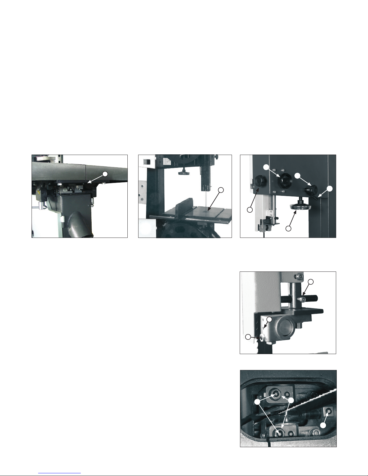
6.6 BLADE MOUNTING AND ADJUSTMENT
To mount blade first remove the steel bar (A of FIG. 6.6) underneath the table, and the table insert ( (A) FIG. 6.7) Place the blade onto the band wheel
checking the teeth are in a correct position, and tighten the tension using the handwheel ( (A) of FIG. 6.8). The correct tension value is indicated on the
tension scale inside the upper door, the indicated value corresponds to the width of the blade. (e.g. for blade width 25 mm tighten until no. 25 appears on
the indicator).
Turn the bandwheels manually, checking that the blade does not interfere with any fixed parts and that the blade is placed correctly on the bandwheels.
The points of the teeth should slightly protrude over the edge of the bandwheels. To adjust the blade position on the bandwheels slacken the locking lever
( (B) of FIG. 6.8), and then turn the knob ( (C) of FIG.6.8): the blade will move inwards when turning the knob clockwise and the blade will move further
out when turning the knob anti-clockwise; A quarter of one turn is sufficient to make a noticeable displacement. Tighten the locking lever after the blade is
positioned correctly.
Then reinstall the table insert, close the band wheels accessing doors.
IMPORTANT NOTE :
After use we recommend slackening the blade tension, and to display a visible sign on the machine advising of this procedure.
Remember to check and re-tension before use. This operation prevents damage to the band wheel tyres.
6.7 SETTING THE SAW BLADE GUIDE & GUARD
ADJUSTING THE SAW BLADE GUARD
The adjustable saw blade guard should be positioned as close as possible to the workpiece. To adjust
the height, release the locking knob ( (D) of Fig.6.8 ) and turn the handwheel ( (E) of Fig. 6.8) to adjust
the guard up or down. Lock the knob once the correct position of guard is obtained.
This operation must always be carried out while the machine is stopped.
BLADE GUIDE ROLLER BEARINGS
The side rollers should almost touch the blade, to prevent vibration during operation and ensure correct
direction of cutting. The positioning of these rollers is controlled by screw ( (A) of Fig.6.9), once they
have been adjusted, tighten grub screw ( (B) of Fig.6.9); they should be 2mm behind the teeth of the
blade. The thrust shaft prevents excessive backward movement of the blade whilst in operation and
should be 1-2 mm from the back of the blade: this can be adjusted by screw ( (C) of Fig.6.9).
LOWER SAW BLADE GUIDE
To adjust the lower blade guide move the table insert and adjust it from the top of the table. The lower
blade guide should be positioned as close as possible to the workpiece (5-10mm)
The side rollers should lightly touch the blade, to prevent vibration during operation and ensure
correct direction of cutting. The positioning of these rollers is controlled by screw ( (A) of Fig.6.10),
once they have been adjusted, tighten nut ( (B) of Fig.6.10); they should be 2mm behind the teeth of
the blade. The thrust shaft prevents excessive backward movement of the blade whilst in operation,
and should be 1-2 mm from the back of the blade: this can be adjusted by screw ( (C) of Fig.6.10).
FIG. 6.9
FIG. 6.10
A
B
C
A
B
C
FIG.6.8FIG. 6.7
FIG. 6.6
A
A
B
C
D
E
A
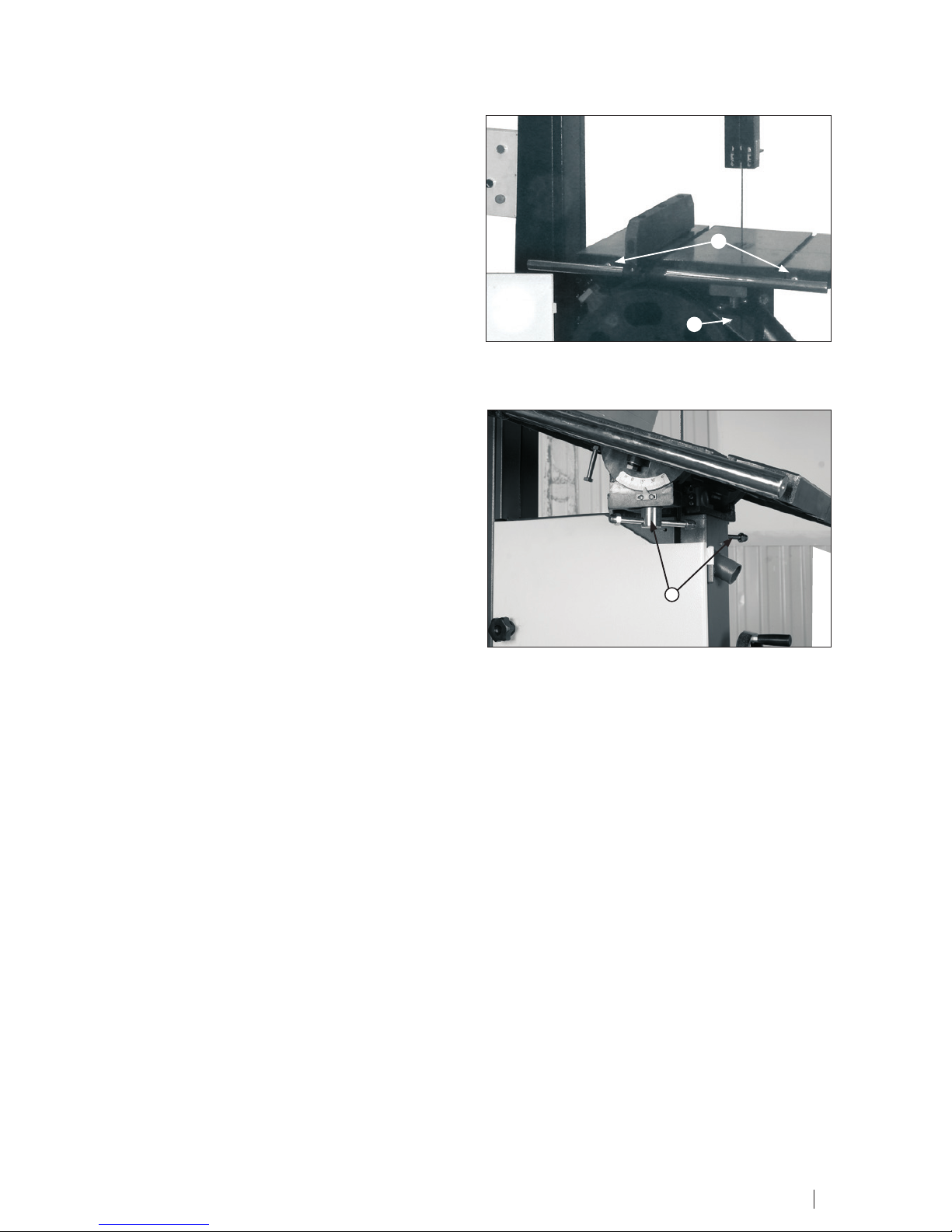
6.8 TABLE INSERT FOR DUST EXTRACTION
The machines are equipped with a removable plastic insert under the worktable(A of FIG.6.11), the insert improves dust extraction. It is recommended
that the insert “ A “ be replaced when the blade cutting clearance widens,
this will maintain maximum efficiency of dust extraction.
6.9 CUTTING DIRECTION AND PARALLELISM
If the cut is not perfectly parallel when using the parallel rip fence the
possible causes are:
• Incorrect grinding and setting of the blade
• Insufficient blade tension
• Incorrect setting of the parallel rip fence in respect of the saw blade;
to adjust the parallelism of the guide, slacken, without removing, the 2
screws (B of FIG. 6.11), adjust the guide position and firmly re-tighten the
2 screws.
6.10 TILTING THE WORK TABLE
The table can be tilted to a maximum of 20°
To incline it, loosen off the locking ratchet handle (FIG. 6.12).
position A. Turn the table by hand until table is at required angle.
FIG. 6.11
B
A
FIG. 6.12
A
12 13

7. Safety Advice
a) Machine out of order
Before making any adjustments or repairs to the machine, disconnect from the electrical supply.
If any faults are suspected, disconnect the electrical supply and put a visible notice on the machine. Always report faults on the machine (including
guards and saw blades) as soon as they are discovered.
b) Before operating
• Keep the surrounding floor space clean;
• Wear suitable clothing, not loose garments;
• Check that the blade is sharp, correctly tensioned, the correct width, and correctly positioned on the bandwheels and always observe the maximum
speed marked on the saw blade;
• Use support stands for long or wide material;
• Use a dust extractor of adequate performance as detailed in section 3.3 of this manual.
c) During operation
Never clean the table with hands, use a brush or a piece of wood.
Do not remove off cuts or work pieces from the cutting area unless by using a push stick.
In case of an emergency such as blade breakage or other emergency do not attempt to intervene before the bandwheels have
completely stopped.
When the band wheel has stopped, lower the upper blade guides to the level of the table, loosen the blade and leave a sign
advising of this operation. REMOVE THE ELECTRICAL CONNECTION PLUG.
d) During maintenance
• Place the machine out of order as indicated above;
• Use gloves to handle the saw band;
• Periodically check the electrical grounding of the machine.
e) Tensioning
When the machine is not in use, for example at the end of a shift, release the saw blade tension and place a notice on the
machine to indicate this and to remind the next user to adjust the tension before starting up.
f) Guard removal/replacement
Where guards are removed replace them in accordance with the manufacturer's instructions.
g) Noise reduction
Regular maintenance of saw blades, extraction system, cleaning and lubrication of the saw blade etc. is necessary to help
control machine noise.
h) Operator training
It is essential that all operators are adequately trained in the use, adjustment and operation of the machine. This covers
in particular:
other principles of machine setting and operation, including the correct use and adjustment of workpiece holding and guiding
devices and guards;
• the safe handling of the workpiece when cutting;
• the use of personal protective equipment for ear and eye protection.
i) Tooling
Care should be taken to avoid damaging the saw blade. When not in use, untensioned band saw blades should be coiled
and secured. They should be stored in a safe, dry place. Before use they should be checked for damaged teeth and cracks.
• To avoid cracking, tensioned saw blades should be stored in accordance with Fig 7.1.
• At least two operators will be needed to change a wide saw blade.
• Suitable carrier equipment should be provided for transporting tensioned wide saw blades.
• Suitable gloves (or other handling aids) should be worn whenever saw blades are handled.
j) Saw blade thrust wheel
The purpose of the thrust wheel on a table band saw is to give support to the saw blade when cutting.
Position it just clear of the back of the saw blade when the saw blade is running free after being strained
and tracked. Lack of clearance will cause grooving of the thrust wheel and lead to saw blade failure.
k) Machine operation
It is necessary to adjust the adjustable saw blade guard as close to the workplace as practicable.
l) Straight work
Always use a fence for straight cutting, to prevent the workplace rocking or sliding.
When hand feeding against the fence, it is necessary to use a push stick for feeding close to the
saw blade.
m) Cross cutting round stock
If cutting round stock it is necessary to secure the workpiece against rotation by using a jig or
holder and to use a saw blade suitable for cross cutting.
n) Operator training
It is essential that all operators are adequately trained in the correct use and adjustment of safety
appliances such as jigs, templates and extension tables.
FIG. 7.1

76 WEDGE CUTTING
Pushing device for wedge cutting FIG 7.5
FIG. 5.4
FIG. 7.5
7.3 FACE CUTTING
Use a square for safe guiding of the work during face cutting FIG. 7.2
7.4 CUTTING SHORT PIECES
Use the push stick provided for the cutting of short pieces. FIG 7.3
FIG. 5.2
7.5 CUTTING OF ROUND PIECES
Use a wedge rest to prevent rotation of round parts during cutting. FIG 7.4
400
FIG. 5.3
45º
250
100
60
FIG. 7.3
FIG. 7.4
7.2 SAFETY DEVICES AND GUARDS
The upper portion of the saw blade is fully protected inside the machine
column.
The lower portion of the blade is protected by an adjustable guard which is
adjustable for height depending on the thickness of material to be cut.
fig. 5.1
180
100
20
120
FIG. 7.2
14 15

7.7 CUTTING OF WEDGE-SHAPED LENGTHS
Equipment for cutting wedge-shaped lengths. FIG 7.6
FIG. 5.5
8. Maintenance
BEFORE ANY INTERVENTION ALWAYS DISCONNECT
THE ELECTRICITY SUPPLY
Periodically check that all screws are tightly fastened and the condition of
the various guards
V belts
After the first few hours of operation it is necessary to check that the
tension of the belts is correct. To control the tension of the belts push the
mid-point of the belt applying 3-4 Kg of pressure, the displacement should
not exceed 5-6 mm. To adjust the belt tension turn the handwheel (A, FIG.
8.1) clockwise, this will increase the tension.
It is recommended that the correct belt tension is maintained as loose belts
reduce the motor power and can increase the braking time. Belts that are
too tight may become hot.
To change the belts
Slacken the tension as described above, remove the screw (“B”, FIG. 8.1),
pull-out the band wheel from the shaft, repeat the operations in reverse
to re-assemble. (CAUTION: Bandwheels are heavy and assistance may be
required)
Dismantling the upper fly-wheel
To remove the upper flywheel, follow the same procedure as for the
bottom flywheel.
Replacement of rubber covering of the fly-wheels
It is recommended that this be carried out by a competent specialist or the
manufacturer. This is because the rubber covering is not only glued onto
the fly-wheel, but also ground in a crown form. It is strongly advised not to
grind and shape the rubber directly on the machine using gouges, files or
abrasives.
Cleaning and lubricating
Periodically clean the inside of the machine with the aid of a dust extractor
for any saw-dust deposits, remove any resinous deposits from the flywheels surface. The fly-wheel bearings do not require any greasing. It is
not necessary to lubricate any part or component of the machine as the
sawdust circulating within will adhere to any oiled or greased surface
jeopardizing the sliding of moving parts such as the shaft of the blade
guide adjustment and the slide of the tensioning group.
Frequently control the cleanliness of the rubber surfaces on the
fly-wheels, particularly in cases of cutting resinous materials or chip-board.
Clean the surfaces, while machine is not in motion ,
of any resinous deposits taking care do not damage the surface.
FIG. 7.6
FIG. 8.1
A
B

9. Trouble Shooting
The motor does not start
• Check that the fly-wheel doors are correctly closed, otherwise the safety switch will not allow operation.
• Check that the emergency button, when fitted, is released.
• If the “ON“ button of the magneto thermal switch does not lock-in, or, when the star delta is fitted, check that the knob of the star delta starter is in
“O” position.
• The motor lacks electrical power: consult an electrician.
The machine does not work efficiently during operation
• Incorrect connection of the motor: consult an electrician.
• Loose drive belts: follow the tightening procedure.
Does not cut straight
• Check the sharpness and setting of the blade
• Check the alignment of the rip fence
The blade has cracks at the base of the teeth
• Incorrect sharpening and consequent overheating, otherwise incorrect setting of the teeth.
• Incorrect blade thickness in relation to bandwheels diameter.
• The band wheel tyres are damaged or have incrustation deposits.
• Badly aligned bandwheels: requires correction by a qualified technician.
The blade is cracked at the back
• Excessive feed during cutting.
• Imperfect weld alignment: eliminate badly welded part and repeat the weld.
• The rear thruster of the blade guide is damaged.
The blade breaks at the weld
• Overheating of the blade during welding: remove the weak area and repeat the welding.
• Cooling down the weld too quickly after welding, proceed as above.
The machine stops with the blade jammed into the workpiece
• Stop the motor and release the brake, widen the cut using a wedge to aid removing the workpiece, after this operation check the
blade and its position on the bandwheels before recommencing.
Other problems
• The blade moves backwards and forwards: weld misaligned.
• The blade slips back at the beginning of cut: blade not sharpened or blade incorrect for material in work or there is a defect on
the crown of the band wheel surface.
16 17

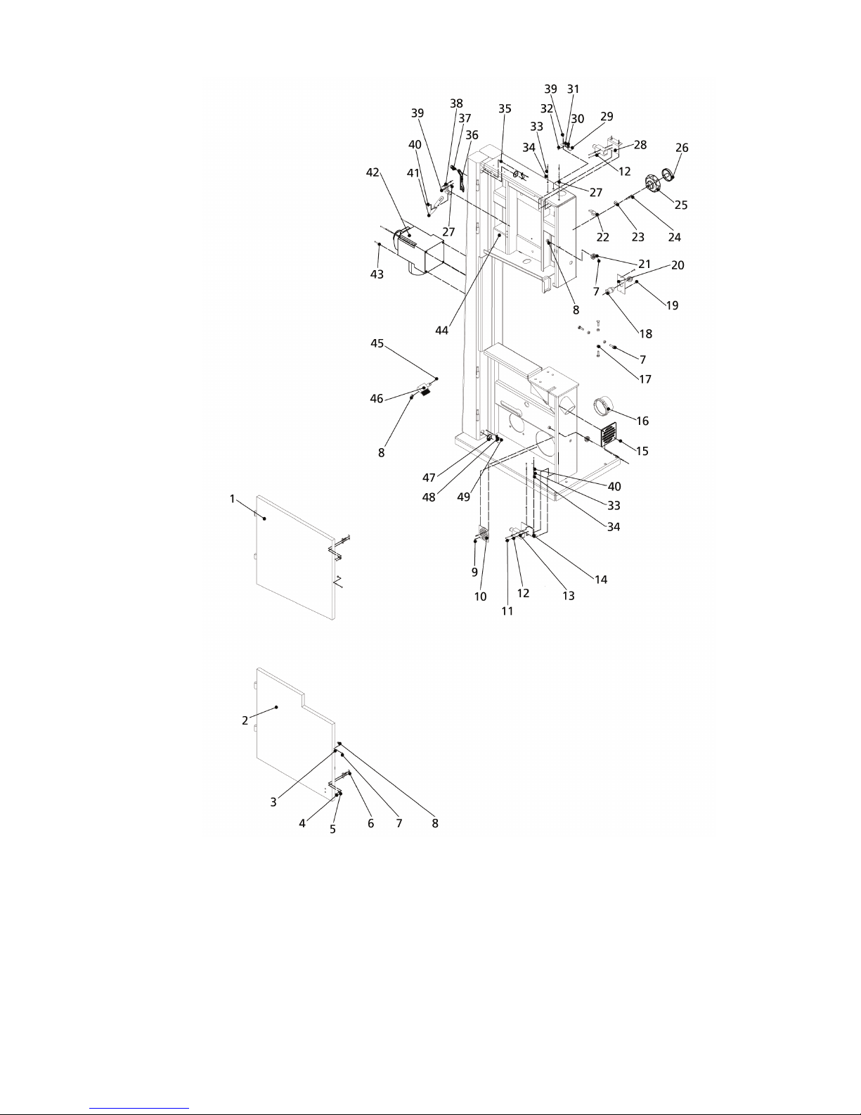
10. Diagrams & Components-502E
Ref No. Description
1 Upper wheel cover
2 Clear window
3 Rivet 3x7
4 Lower wheel cover
5 Bushing
6 Pan head screw M4X12
7 Flat washer 4
8 Thread plate
9 Hex. Socket head screw M6X20
10 Hex. Nut M6
11 Rubber bushing
12 Clamp plate
13 Screw M5X10
14 Tapping screw 3.5X13
15 Dust bar screen
16 Safety switch
17 Hex. Nut M4
18 Switch plate
19 Spring washer 4
20 Dust port
21 Hex. Nut M8
22 Screw M8X25
23 Strain relief M20
24 Strain relief M16
25 Pan head screw M6X8
26 Cable plate
27 Star handle
28 Locknut M6
29 Lock handle
30 Adjusting handle
31 Ring
32 Frame
33 Plastic pusher
34 Screw M6X25
35 Indicator plate
36 Flat washer 5
37 Pan head screw M5X6
38 Screw
39 Indicator
40 Tension label
41 Screw M4X50
42 Switch
43 Flat washer 6
44 Spring washer 6
45 Hex. Socket head screw M6X12
46 Tapping screw 4.8x16
47 Brush holder
48 Brush
49 Hex. Bolt M6X20
50 Board

Ref No. Description
1 Hex. Socket head screw M6X10
2 Spring
3 Lock handle
4 Hex. Rod
5 Fence bracket
6 Bracket
7 Fence
8 Spring washer 8
9 Screw M8X25
10 Flat washer 8
11 Table
12 Set screw M5X4
13 Table insert
14 Guide rail
15 Guide rail support
16 Hex. Nut M10
17 Flat washer 10
18 Screw M6X20
19 Mitre gauge fence
20 Pan head screw M5X10
21 Angle scale
22 Rivet 2.5x5
23 Indicator
24 Lock handle
25 Bushing
26 Spring
27 Roll pin 3X16
28 Screw M5X14
29 Mitre gauge guide bracket
30 Mitre gauge sliding block
31 Mitre gauge base
32 Guide block
33 Hex. Bolt M10X70
34 Table bracket
35 Hex. Bolt M8X20
36 Hex. Bolt M10X55
37 T bolt
38 Table sliding block
39 Hex. Bolt M10X45
40 Set screw M10X25
41 Spring washer 10
42 Angle scale
43 Hex. Bolt M10X30
44 Hex. Socket head screw M4X10
45 Indicator
46 Lock handle
47 Handle rod
48 Cap nut M10
49 Trunnion support bracket
50 Hex. Nut M8
51 Set screw M8X12
52 Shaft
53 Pin nail
54 Hex. Nut M6
55 Hex. Socket head screw M6X10
56 Pan head screw M4X8
57 Flat washer 4
58 Spring washer 4
59 Left end cap
60 Bushing
61 Guide panel
62 Flat washer 4
63 Right end cap
64 Pan head screw M4X8
65 Shaft
66 Hex. Socket head screw M8X45
67 Lower guide support
68 Rear bracket
69 Rear support base
70 Screw M8X8
18 19

Ref No. Description
1 Locknut M6
2 Flat washer 6
3 Gear
4 Spring washer
5 Set screw M6X12
6 Upper blade guide support
7 Spring plate
8 Flat washer 5
9 Spring washer 5
10 Hex. Socket head screw M5X10
11 Adjusting knob
12 Hex. Bolt M8X40
13 Hex. Nut M8
14 Flat washer 8
15 Spring washer 8
16 Hex. Bolt M8X16
17 Adjusting shaft
18 Handle
19 Hex. Socket head screw M6X12
20 Spring washer 6
21 Protective cover
22 Sliding panel
23 Guide rack
24 Hex. Socket head screw M6X10
25 Retaining ring 30
26 Flat washer 5
27 Pan head screw M5X8
28 Rear support bar
29 Support plate
30 Flat washer 6
31 Hex. Bolt M6X16
32 Side support base
33 Guide panel
34 Bushing
35 Flat washer 4
36 Pan head screw M4X8
37 Adjusting bushing
38 Set screw M8X8
39 Set screw M8X12
40 Hex. Nut M8
41 Bushing
42 Pin nail
43 Hex. Socket head screw M8X20
44 Hex. Nut M6
45 Screw M6X10

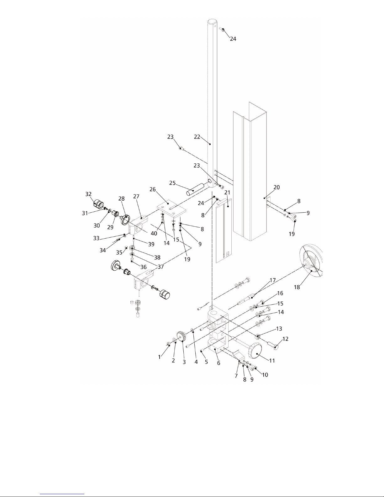
Ref No. Description
1 Set screw M6X12
2 Big Handwheel
3 Thread rod
4 Hex. Bolt M10X25
5 Spring washer 10
6 Lower bracket
7 Shaft
8 Flat washer
9 Spring
10 Spring washer 50
11 Flat washer 24
12 Bushing
13 Sliding block
14 Set screw M8X20
15 Locknut M12
16 Flat washer 10
17 Spring washer 12
18 Cap nut M12
19 Hex. Nut M10
20 Thread rod
21 Flat washer 12
22 Joint block
23 Upper wheel shaft
24 Set screw M8X8
25 Roll pin 3x30
26 Bearing
27 Roll pin 3x16
Ref No. Description
1 Saw blade
2 Screw M8X16
3 Washer 8
4 Retaining ring 47
5 Bearing
6 Bearing
7 Tyre
8 Upper wheel
9 Lower wheel
10 shaft
11 Retaining ring 12
12 Bearing
13 Retaining ring 28
14 Tension wheel
15 Motor pulley
16 Left-hand bolt M8X20
17 V belt
18 Threaded rod
19 Retaining tube
20 Screw M5X8
21 Small handwheel
22 Small handle
23 Screw M6X12
24 Motor
25 Key 6x28
26 Washer 8
27 Lower wheel shaft
28 Washer 27
29 Hex. Nut M27
20 21
10. Diagrams & Components-352E
Ref No. Description
1 Upper wheel cover
2 Lower wheel cover
3 Bushing
4 Pan head screw M4X10
5 Flat washer 4
6 Thread plate
7 Hex. Socket head screw M6X20
8 Locknut M6
9 Tapping screw 3.5X9.5
10 Dust bar screen
11 Pan head screw M4X30
12 Spring washer 4
13 Safety switch
14 Switch plate
15 Dust bar screen
16 Dust port
17 Hex. Nut M6
18 Strain relief M20
19 Pan head screw M6X8
20 Cable plate
21 Star handle
22 Wing nut
23 Hex. Nut M8
24 Hex. Bolt M8X60
25 Knob body
26 Knob cap
27 Hex. Nut M5
28 Switch plate
29 Gemel
30 Spring
31 Gemel
32 Pin shaft
33 Spring washer 5
34 Flat washer 5
35 Frame
36 Plastic pusher
37 Screw M6X25
38 Indicator plate
39 Pan head screw M5X16
40 Screw
41 Indicator
42 Switch
43 Pan head screw M4X50
44 Tension scale
45 Hex. Bolt M6X25
46 Brush
47 Rubber holder
48 Clamp plate
49 Screw M5X10

Ref No. Description
1 Hex. Socket head screw M6X10
2 Spring
3 Lock handle
4 Hex. Rod
5 Fence bracket
6 Bracket
7 Fence
8 Flat washer 6
9 Spring washer
10 Hex. Socket head screw M6X25
11 Table
12 Set screw M5X4
13 Table insert
14 Guide rail
15 Guide rail support
16 Hex. Nut M8
17 Flat washer 8
18 Hex. Nut M10
19 Screw M6X20
20 Mitre gauge fence
21 Pan head screw M5X10
22 Angle scale
23 Rivet 2.5X5
24 Indicator
25 Lock handle
26 Bushing
27 Spring
28 Roll pin 3x16
29 Screw M5X14
30 Mitre gauge guide bracket
31 Mitre gauge sliding block
32 Mitre gauge base
33 Guide block
34 Hex. Bolt M10X70
35 Table bracket
36 Spring washer
37 Hex. Bolt M8X20
38 Hex. Bolt M10X55
39 T bolt
40 Table sliding block
41 Hex. Bolt M8X40
42 Set screw M8X25
43 Angle scale
44 Flat washer 10
45 Hex. Nut M10
46 Hex. Bolt M10X30
47 Pan head screw M4X8
48 Indicator
49 Lock handle
50 Trunnion support bracket
51 Hex. Nut M8
52 Set screw M8X12
53 Shaft
54 Pin nail
55 Hex. Nut M6
56 Hex. Socket head screw M6X10
57 Pan head screw M4X8
58 Spring washer 4
59 Flat washer 4
60 Left end cap
61 Guide panel
62 Bushing
63 Flat washer 4
64 Right end cap
65 Pan head screw M4X8
66 Shaft
67 Hex. Socket head screw M8X25
68 Lower guide support
69 Rear bracket
70 Rear support base
71 Set screw M8X8
72 Cap nut M10
73 Adjusting rod
22 23
Ref No. Description
1 Locknut M6
2 Flat washer 6
3 Gear
4 Spring washer
5 Set screw M6X12
6 Upper blade guide support
7 Spring plate
8 Flat washer 5
9 Spring washer 5
10 Hex. Socket head screw M5X10
11 Lock handle
12 Hex. Bolt M8X30
13 Hex. Nut M8
14 Flat washer 8
15 Spring washer 8
16 Hex. Bolt M8X16
17 Adjusting shaft
18 Handle
19 Hex. Socket head screw M5X12
20 Protective cover
21 Sliding panel
22 Guide rack
23 Hex. Socket head screw M5X8
24 Pan head screw M5X8
25 Rear support bar
26 Support plate
27 Side support base
29 Guide panel
30 Bushing
31 Flat washer 4
32 Pan head screw M4X8
33 Adjusting bushing
34 Hex. Nut M6
35 Screw M6X10
36 Set screw M8X8
37 Set screw M8X12
38 Hex. Nut M8
39 Bushing
40 Pin nail
41 Hex. Socket head screw M8X12

Ref No. Description
1 Set screw M6X12
2 Small handwheel
3 Thread rod
4 Hex. Socket head screw M8X30
5 Spring washer 10
6 Lower bracket
7 Shaft
8 Flat washer
9 Spring
10 Spring washer 42
11 Flat washer 20
12 Bushing
13 Sliding block
14 Set screw M8X25
15 Locknut M10
16 Flat washer 10
17 Flat washer 12
18 Spring washer 12
19 Cap nut M12
20 Hex. Nut M10
21 Thread rod
22 Joint block
23 Upper wheel shaft
24 Set screw M8X8
25 Roll pin 3x30
26 Bearing
27 Roll pin 3x16
Ref No. Description
1 Saw blade
2 Hex. Socket head screw M8X16
3 Spring washer 8
4 Flat washer M8
5 Retaining ring 40
6 Bearing
7 Bearing bushing
8 Tyre
9 Upper wheel
10 Shaft
11 Bearing
12 Retaining ring 28
13 Tension wheel
14 Retaining ring 12
15 Set screw M6X8
16 Motor pulley
17 Multi-belt
18 Lower wheel
19 Thread rod
20 Retaining tube
21 Set screw M5X8
22 Small handwheel
23 Small handle
24 Hex. Socket head screw M6X16
25 Motor
26 Roll pin 6x20
27 Hex. Bolt M6X16
28 Spring washer 6
29 Lower wheel shaft
30 Hex. Nut
24 25

Ref No. Description
1 Joint panel
2 Hex. Bolt M8X16
3 Locknut M6
4 Flat washer 6
5 Flange nut M6
6 Left panel
7 Hex. Bolt M6X45
8 Flat washer 8
9 Spring washer
10 Hex. Nut M8
11 Hex. Bolt M8X20
12 Support bracket
13 Right panel

EU Declaration of Conformity
Cert No: EU / 502E-352E / 1
RECORD POWER LIMITED,
Unit B, Ireland Industrial Est.
Adelphi Way, Staveley, Chesterfield S43 3LS
declares that the machinery described:-
1. Type: Bandsaw
2. Model Numbers: 502E/352E
3. Serial No .........................................................................
Conforms with the following directives:-
MACHINERY DIRECTIVE 2006/42/EC
(repealing / replacing Directives
LOW VOLTAGE DIRECTIVE 2006/95/EC
and its subsequent amendment
ELECTROMAGNETIC 2004/108/EC
COMPATIBILITY DIRECTIVE EN 55014-1:2006
and its subsequent amendments EN 61000-3-2:2006
EN 61000-3-3:1995+A1+A2
EN 55014-2:1997+A1
and conforms to the machinery example for which the
EC Type-Examination Certificate No. BM50171398, AN50171396, AE50111673.
has been issued by TUV Rheinland Product Safety GmbH,
at: Am Grauen Stein, D-51105. Cologne, Germany
and complies with the relevant essential health and safety requirements.
Signed...........................................................Dated: 01/07/2011
Andrew Greensted
Managing Director
26 27
Startrite
Unit B, Adelphi Way
Ireland Industrial Est.
Staveley S43 3LS
Industrial Woodworking Machines & Accessories
Telephone: 01246 561 520
Facsimile: 01246 561 537
Email: sales@recordpower.co.uk
www.recordpower.co.uk
Visit
www.startrite.co.uk for
the full range of
Startrite products.
Woodworking
Machinery
Craft Accessories
DVDs Accessories
Finishes and Waxes
Blades
In association with
Woodturning
Projects
Mantle Clock
by
Alan Holtham
In association with
Woodturning
Techniques
An Introduction to Spindle Turning
by
Alan Holtham
In association with
Step by Step
Guide
Finishing on the Lathe
by
Alan Holtham
Buyer’s Guide Series
The essential guides to the most popular ranges of woodworking machinery
And visit www.recordpower.co.uk for
 Loading...