

Page 1
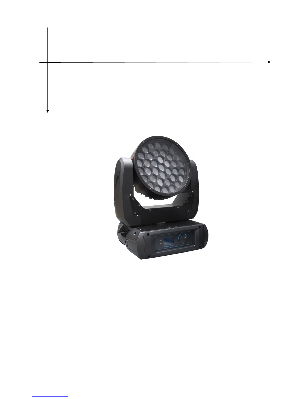
LED ZOOM WASH MOVING HEAD
ST-3715 37X15W
USER MANUAL
Ver1.0
Page 2

1
Table of contents
1. Preface 2
1.1 Packing list 2
1. 2 Unpac ki ng inst ructio ns 2
1.3 AC Po we r 2
1.4 Safety instructions 2
2. Introduction 3
2.1 Features 3
2. 2 DMX cha n ne l 3
3. Setup 3
3.1 Fuse replacement 4
3. 2 Fi x ture li nki ng 4
Da ta ca bl i ng 4
DM X da ta ca ble 4
3.3 3-Pin to 5-Pin conversion chart 4
3.4 Setting up a DMX serial data link 4
3.5 Master/Slave fixture linking 4
3.6 orientation 5
4. Operating instructions
5
4.1 Navigating the control panel 5
4. 2 Me n u ma p 5
DMX mode 5
4. 3 DMX ch a nne l va l ue s 6
5. Technical specifications 7
Page 3

2
Please read these instructions CY, it includes important information about the
installation, usage and maintenance of this product.
Warning! Verify that the voltage select switch on your unit matches the line
voltage applied. Damage to your fixture may result if the line voltage applied
does not match the voltage indicated on the voltage selector switch. All fixtures
must
be
connected
to
circuits
with
a
suitable
Earth
ground.
1. Preface
1.1 Packing list
Product name quantity
moving head light 1 pcs
Power -line 1 base
User manual 1 pcs
1. 2 Unp ac k ing ins truc tio ns
On receiving a fixture, carefully unpack the carton, check the contents to ensure
that all parts are presented, and have been received in a good condition. Notify the
shipper immediately and retain packing material for inspection if any parts appear
damaged from shipping or the carton itself shows, sign of mishandling. Save the
carton and all packing materials. In the event that a fixture must be returned to the
factory, it is important that the fixture should be returned in original factory box and
packing.
1.3 AC Po we r
To determine the power requirements for a particular fixture, see the label affixed to
the back plate of the fixture or referred to the fixtures specification chart. A fixture
listed current rating is its average current draw under normal conditions. All fixtures
must be directly powered off a switched circuit and cannot be run off a rheostat
(variable resistor) or dimmer circuit, even if the rheostat or dimmer source voltage
matches the fixtures requirement. Check the fixture or device carefully to make sure
that if a voltage selection switch exists that it is set to the correct line voltage you
will use.
1.4 Safety instructions
Please keep this user guide for future consultation. If you sell the unit to another
user, be sure that they also receive this instruction booklet.
Always make sure that you are connecting to the proper voltage, and that the line
voltage you are connecting to is not higher than that stated on the decal or rear
panel of the fixture.
This product is intended for indoor use only!
To prevent risk of fire or shock, do not expose fixture to rain or moisture. Make sure
that there are no flammable materials close to the unit while operating.
The unit must be installed in a location with adequate ventilation, at least 20in
(50cm) from adjacent surfaces. Be sure that no ventilation slots are blocked.
Always disconnect from power source before servicing or replacing fuse and be
sure to replace with same fuse size and type.
Secure fixture to fastening device using a safety chain. Never carry the fixture
solely by its head. Use its carrying handles.
Page 4
3
Maximum ambient temperature (Ta) is 104 ℉ (40 ℃ ). Do not operate fixture at
temperatures higher than this.
In the event of a serious operating problem, stop using the unit immediately. Never
try to repair the unit by yourself. Repairs carried out by unskilled people can lead to
damage or malfunction. Please contact the nearest authorized technical assistance
center. Always use the same type spare parts.
Don’t connect the device to a dimmer device.
Make sure the power cord never crimped or damaged.
Never disconnect the power cord by pulling or gugging on the cord.
Avoid direct eye ex-positing to the light source while it is on.
2. Introduction
2.1 Features
25 channel DMX-512.
Pan :540°/ tilt:270°.
Variable electronic strobe.
Variable electronic dimmer (0-100%).
LCD display
Reset to factory settings option.
Pan/tilt inverts option.
Fan cooled.
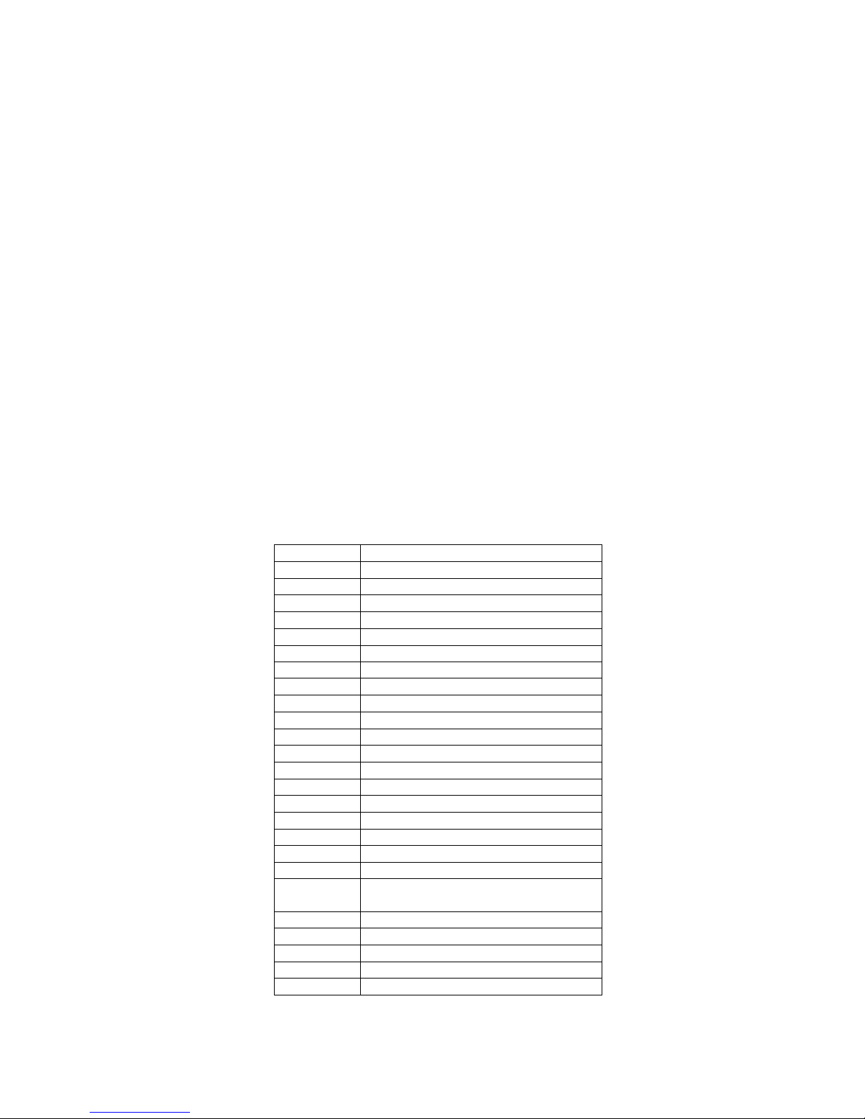
2. 2 DM X cha nne l
Channel Function
1
Pan
2 Tilt
3 Pan/Tilt Speed
4
Red(Area
A)
5 Green(Area A)
6
Blue(Area
A)7White(Area
A)8Amber(Area
A)9Red(Area
B)
10 Green(Area B)
11
Blue(Area
B)12White(Area
B)
13 Amber(Area B)
14
Red(Area
C)
15 Green(Area C)
16
Blue(Area
C)17White(Area
C)18Amber(Area
C)19Color
Change
20 switching the
LEDs/Strobe/Reset
21
Dimmer
22 Pan Fine
23
Tilt
Fine24Color
Macro
25 Zoom
Page 5
4
3. Setup
Disconnect the power cord before replacing a fuse and always replace with the same
type fuse.
3.1 Fuse replacement
With a flat head screwdriver wedge the fuse hold out of its housing. Remove the
damaged fuse from its holder and replace with exact same type fuse. Insert the fuse
holder back in its place and reconnect power.
3. 2 Fi x ture linkin g
You will need a serial data link to run light show of one or more fixtures using a
DMX-512 controller or to run synchronized on two or more fixtures set to a
master/slave operating mode. The combined number of channels required by all
the fixtures on a serial data link determines the number of fixtures the data link can
support.
Maximum recommended serial data link distance: 500 meters (1640ft).
Maximum recommended number of fixtures on a serial data link: 32 fixtures.
Da ta ca bl i ng
To link fixtures together you must obtain data cables. If you choose to create your
own cable please use data-grade cables that can carry a high quality signal and are
less prone to electromagnetic interference.
DM X da ta ca ble
Use a belden 9841 or equivalent cable which meets the specifications for EIA
RS-485 applications. Standard microphone cables cannot transmit DMX data
reliably over long distances. The cable will have the following characteristics:
2-conductor twisted pair plus a shield.
Maximum capacitance between conductors-30 pF/ft.
Maximum capacitance between conductor and shield -55 pF/ft.
Maximum resistance of 20 ohms/1000ft.
Nominal impedance 100-140 ohms.
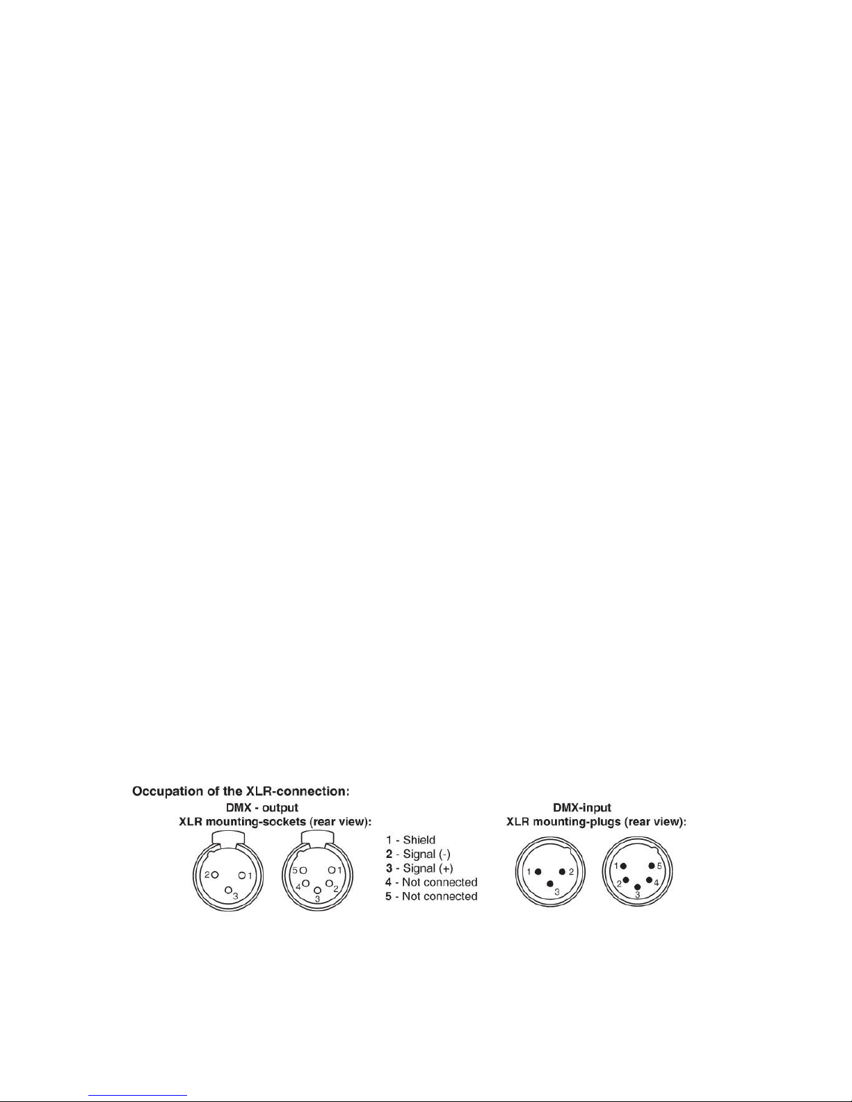
3. 3 3- Pi n to 5-P in co nv ersi o n cha rt
Note! If you use a controller with a 5 pin DMX output connector. You will need to use
a 5pin to 3 pin as apter
CHAUVET Model No: DMX5M. Or DMX 5F
The chart below details a proper cable conversion:
3.4 Setting up a DMX serial data link
3.5 Master/S lave fi xtu re linki ng
1. Connect the (male) 3 pin connector side of the DMX cable to the output (female)
3pin connector of the first fixture.
Page 6
5
2. Connect the end of the cable coming from the first fixture which will have a
(female) 3 pin connector to the input connector of the next fixture consisting of a
(male) 3 pin connector. Then, proceed to connect from the output as stated above
to the input of the following fixture and so on.
3.6 or ie n tati on s
This fixture may be mounted in any position provided there is adequate room for
ventilation.
4. Operating instructions
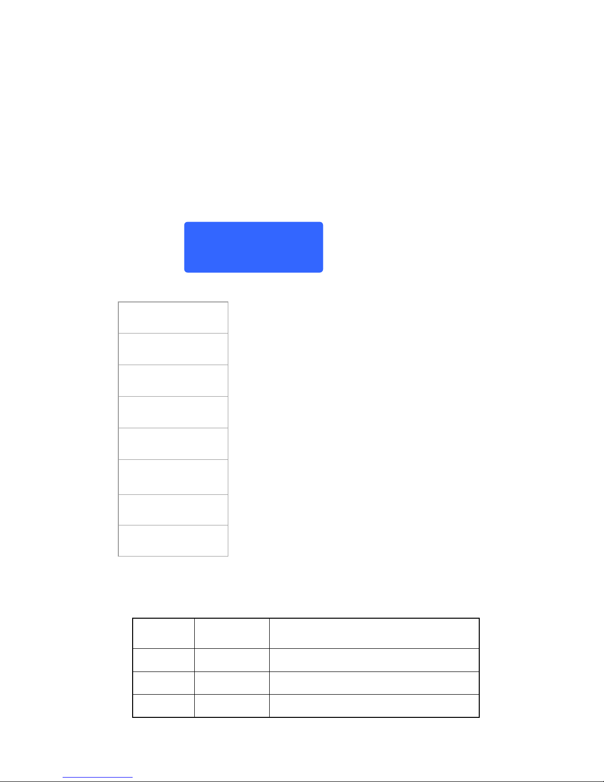
4.1 MENU
The fixture will shown below after power on.
After rest, you can choose the mode what you want via wheel
MENU DETAILS
DMX512 Mode
Address Code: 001
Setting DMX address
Address 001-512
Perform Mode
FAST SLOW
Auto Mode
Fast and slow
Sound Control
EF1 EF2
Sound control
EF1 sound mode 1 ,EF2 sound mode 2
Pan Reverse
YES NO
Pan reverse
YES NO
Tilt Reverse
YES NO
Tilt Reverse
YES NO
Factory Set
YES NO
Factory Set
YES NO
Reset Set
YES NO
Reset
YES NO
Note: Default setting with DMX address 001, For perform mode run inquickmode,
Pan reverse YES and Tilt Reverse YES
4. 2 DM X cha nne l val ue s
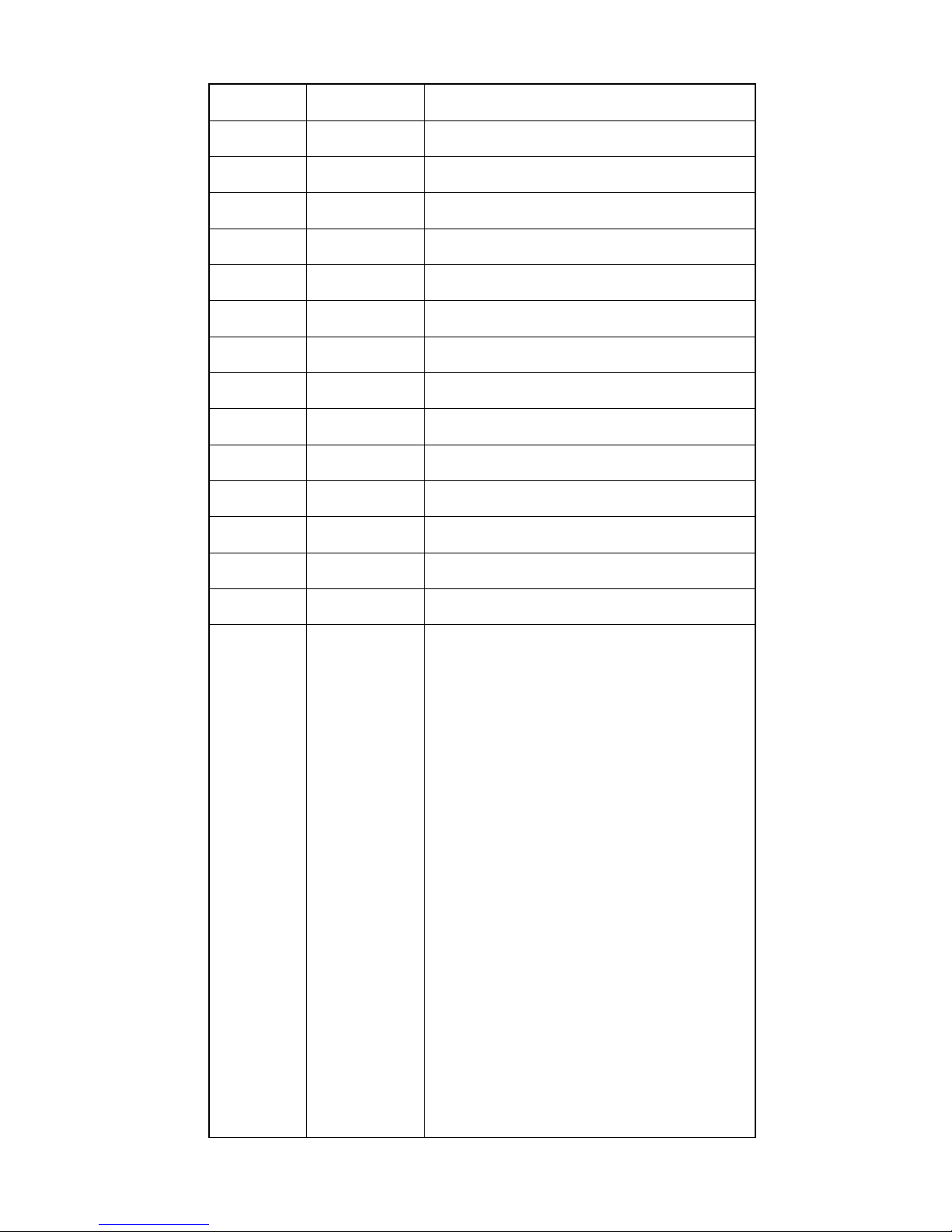
Channel Value Function
1
0-255
Pan
Pan movement 0~540
2
0-255
Tilt
Tilt movement 0~270
3
0-255
Pan Tilt speed
Pan & Tilt speed adjustment
System
init
Please
wait...
Page 7
6
4
0-255
Red (Area A)
0-100%
5
0-255
Green (Area A)
0-100%
6
0-255
Blue (Area A)
0-100%
7
0-255
White (Area A)
0-100%
0-255
Amber (Area A)
0-100%
8
0-255
Red (Area B)
0-100%
9
0-255
Green (Area B)
0-100%
10
0-255
Blue (Area B)
0-100%
11
0-255
White (Area B)
0-100%
0-255
Amber (Area B)
0-100%
12
0-255
Red (Area C)
0-100%
13
0-255
Green (Area C)
0-100%
14
0-255
Blue (Area C)
0-100%
15
0-255
White (Area C)
0-100%
0-255
Amber (Area C)
0-100%
16
0-7
8-15
16-23
24-31
32-39
40-47
48-55
56-63
64-71
72-79
80-87
88-95
96-103
104-111
112-119
120-127
128-135
136-143
144-151
152-159
160-167
168-175
176-183
184-191
192-199
200-207
208-215
216-223
Color Change
Neutral
Amber
Red
Green
Blue
White
Red/Green
Red/Blue
Red/White
Green/Blue
Green/White
Blue/White
Red/Green/Blue
Red/Green/White
Green/Blue/White
Blue/Red/White
Red/Green/Blue/White
Red +Amber
Blue + Amber
Green + Amber
White + Amber
Red/Green + Amber
Red/Blue + Amber
Red/White + Amber
Green/Blue + Amber
Green/White + Amber
Blue/White + Amber
Red/Green/Blue + Amber
Page 8
7
224-231
232-239
240-247
248-255
Red/Green/White + Amber
Green/Blue/White + Amber
Blue/Red/White + Amber
Red/Green/Blue/White
+
Amber
17
0-10
11-20
21-30
31-200
201-250
251-255
Switching the LEDs/Strobe/Reset
LED OFF
Neutral
Reset
Strobe-effect with increasing speed
Random strobe-effect with increasing speed
Neutral
18
0-255
Dimmer
0-100% Dimmer
19
0-255
Pan Fine
Pan fine
20
0-255
Tilt Fine
Pan fine
21
0-10
11-127
128-255
Color Macro
Neutral
Macro1(Slow)
Macro2(Fast)
22
0-255
Zoom
Small to big
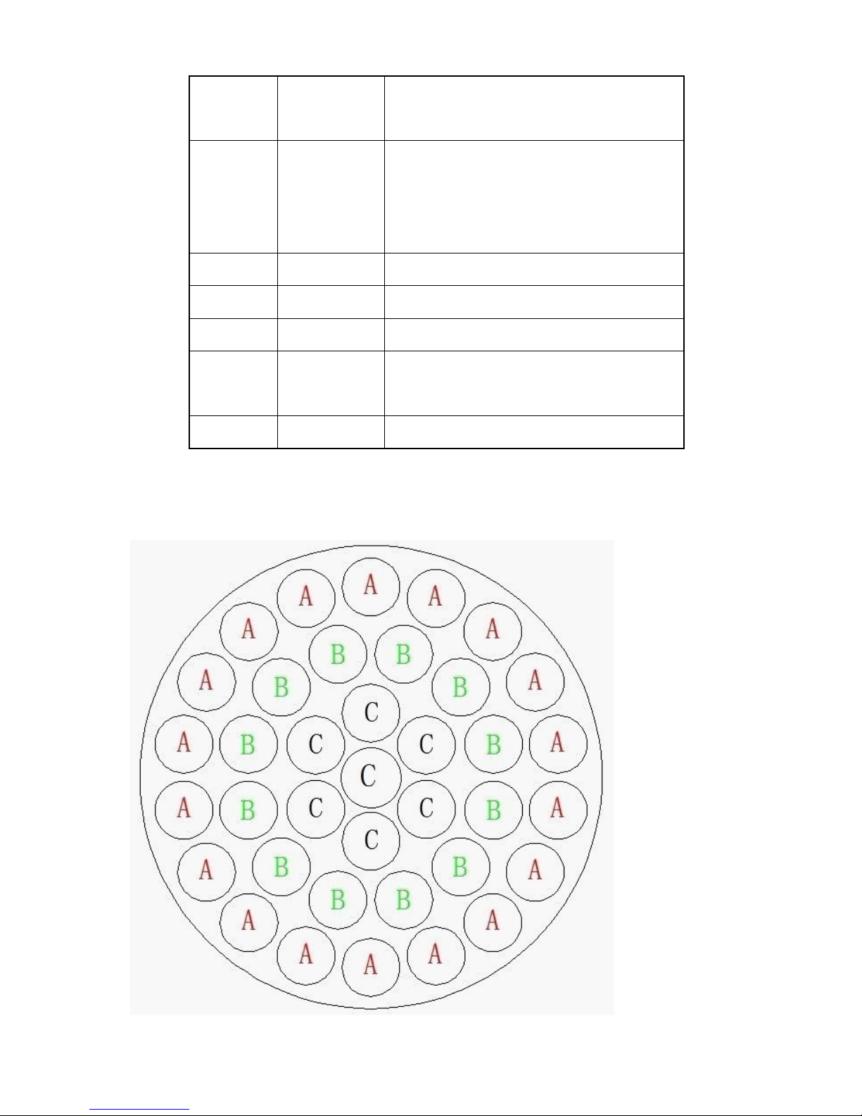
4. 4 LE D Ar e as
Page 9

8
5. techno-specification illuminates
Voltage 100V-240V 50Hz-60HZ
LEDs 37*15w 5 in 1 LEDs
Pan 540°
Tilt 270°
Tiptop environment temperature 104°F(40°C)
Date input/output
3pin XLR-connection、anode socket
N.W 13.1KG
Size 41x41x41.5cm
 Loading...