


Impact
Owner’s Manual
Star Trac StrengthTM
Star Trac FitnessTM

Impact Owner’s Manual
2008
STAR TRAC STRENGTHTM, INC.
41180 Raintree Court, Murrieta, California 92562
Phone 951.600.3800 • Fax 951.600.1706
All rights reserved
Disclaimer:
STAR TRAC STRENGTHTM makes no representations or warranties regarding the contents of this manual. We reserve the right
to revise this document at any time or to make changes to the product described within it without notice or obligation to notify any
person of such revisions or changes.
©2008 Star Trac. All rights reserved. Star Trac, the Star Trac logo are registered trademarks of Unisen, Inc. Impact Strength is a
trademark of Unisen, Inc. LockNLoad is a trademark of Innovative Strength Technology, LLC.

Table of Contents
Safety Information and General Exercise Guidelines ------------------------------------------------ 1
Exercise Guidelines---------------------------------------------------------------------------------------------5
Product Maintenance and Use--------------------------------------------------------------------------------6
Installation Instructions ------------------------------------------------------------------------------------ 8
Securing Equipment in Installation-----------------------------------------------------------------------8
Assembly and Operational Instructions----------------------------------------------------------------- 9
Abdominal-------------------------------------------------------------------------------------------------------9
Abductor-------------------------------------------------------------------------------------------------------10
Adductor-------------------------------------------------------------------------------------------------------10
Biceps Curl---------------------------------------------------------------------------------------------------- 11
Unilateral Biceps Curl--------------------------------------------------------------------------------------11
Chin/Dip Assist----------------------------------------------------------------------------------------------- 12
Deltoid Raise-------------------------------------------------------------------------------------------------- 13
Rear Deltoid /Pec Fly --------------------------------------------------------------------------------------- 13
Glute Machine------------------------------------------------------------------------------------------------14
Incline Chest--------------------------------------------------------------------------------------------------15
Kneeling Leg Curl------------------------------------------------------------------------------------------- 16
Lat Pull Down ------------------------------------------------------------------------------------------------16
Lat Pull Down (Cable)-------------------------------------------------------------------------------------- 17
Leg Curl ------------------------------------------------------------------------------------------------------- 17
Leg Extension (Center Mount)---------------------------------------------------------------------------18
Leg Extension (Side Mount) ------------------------------------------------------------------------------19
Leg Press------------------------------------------------------------------------------------------------------- 20
Low Back------------------------------------------------------------------------------------------------------20
Low Row------------------------------------------------------------------------------------------------------- 21
Overhead Triceps-------------------------------------------------------------------------------------------- 21
Pectoral Fly --------------------------------------------------------------------------------------------------- 22
Seated Leg Curl---------------------------------------------------------------------------------------------- 22
Seated Leg Press ---------------------------------------------------------------------------------------------23
Shoulder Press------------------------------------------------------------------------------------------------ 23
Standing Calf -------------------------------------------------------------------------------------------------24
Triceps Dip---------------------------------------------------------------------------------------------------- 24
Triceps Extension-------------------------------------------------------------------------------------------- 25
Unilateral Row ----------------------------------------------------------------------------------------------- 25
Chest Press ----------------------------------------------------------------------------------------------------26
Vertical Row-------------------------------------------------------------------------------------------------- 26
30° Pectoral Fly ---------------------------------------------------------------------------------------------- 27
45° Calf--------------------------------------------------------------------------------------------------------- 27
DAP – Dual Adjustable Pulley ---------------------------------------------------------------------------28
Transmission Source Replacement----------------------------------------------------------------------30
Transmission Sources--------------------------------------------------------------------------------------- 30
General Guidelines ------------------------------------------------------------------------------------------- 30
Belts - Fasteners----------------------------------------------------------------------------------------------- 31
Belts - Replacement Procedures----------------------------------------------------------------------------33
Attaching Belt to Top Plate (Synch Fastener)------------------------------------------------------ 33
Attaching Belt to Swivel Appliance (Compression Swivel Fastener) ------------------------- 33
Attaching Belt to Drive Systems (Compression Fastener)--------------------------------------- 34

Belts - Installation--------------------------------------------------------------------------------------------- 35
Cables----------------------------------------------------------------------------------------------------------- 35
Type 1. Terminal / Swedge Fitting--------------------------------------------------------------------35
Double Termination Smith Cable--------------------------------------------------------------------- 35
Triceps Pushdown Station(s)---------------------------------------------------------------------------36
Adjustable Cross Over Cable(s)-----------------------------------------------------------------------36
Cross Over Cables (Non Adjustable)-----------------------------------------------------------------38
Frame and Upholstery Management--------------------------------------------------------------------39
Framework Maintenance------------------------------------------------------------------------------------39
Upholstery Maintenance------------------------------------------------------------------------------------- 40
Warranty Information-------------------------------------------------------------------------------------41
Warranty & Disclaimer. -----------------------------------------------------------------------------------41
How to Get Parts & Service ---------------------------------------------------------------------------- 42
Preventative Maintenance---------------------------------------------------------------------------------44
Clean the Shrouds----------------------------------------------------------------------------------------- 48
Sticker Part Numbers--------------------------------------------------------------------------------------50
Appendix A: Synch Fastener Torque Specifications-------------------------------------------------56
Appendix B : Guide Rod Lubrications Procedure ---------------------------------------------------58
Appendix C: DAP handle inspection and tightening procedure-----------------------------------61

Chapter
Safety Information and
General Exercise
Guidelines
Before using this product, it is essential to read this ENTIRE operations
manual and ALL installation Instructions. It describes equipment setup
and instructs members on how to use it correctly and safely.
Health related injuries may result from incorrect or excessive use of
exercise equipment. Star Trac strongly recommends you to encourage
your members to discuss their health program or fitness regimen with a
health care professional, especially if they have not exercised for several
years, are over 35, or have known health conditions.
All STAR TRAC STRENGTHTM equipment MUST be secured to
the floor to stabilize and eliminate rocking or tipping over. This
must be performed by a licensed contractor.
Caution, pinch points. Keep hands, feet, head, limbs, fingers and hair
clear at all times from moving parts to avoid injury. Use appropriate
positioning, speed and controlled movements.
1

Important Safety Instructions
The following fitness safeguards and operating precautions are directed to
purchasers and users of the STAR TRAC STRENGTHTM equipment. Club
Managers should ensure that members and fitness staff are trained to use the
equipemtn properaly and follow these instructions. Failure to follow these
safeguards may result in injury or serious health risk.
SAVE THESE INSTRUCTIONS FOR FUTURE REFERENCE
Read the Owner's Manual fully and carefully before assembling, servicing or using
the Weight equipment.
! WARNING: Serious injury could occur if these safety
precautions are not observed:
1. Do not use any equipment in any way other than designed or intended
by the manufacturer. It is imperative that weight stack machines as
well as any other STAR TRAC STRENGTHTM equipment is used
properly to avoid injury. Call your dealer or Star Trac at (800) 503-1221, or
USA 1-714-669-1660 for examination and repair.
2. Keep hands, feet, head, limbs, fingers and hair clear at all times from
moving parts to avoid injury. Use appropriate positioning, speed and
controlled movements.
3. Do not insert any object, hands or feet into any openings, or expose
hands, arms or feet to the drive mechanism or other potentially moving
part of the equipement.
4. DO NOT exceed maximum user weight of 350 lbs.
5. DO NOT use any equipment that is damaged and or has worn or
broken parts. Use only replacement parts supplied by STAR TRAC
STRENGTHTM.
6. DO NOT wear loose or dangling clothing while using the STAR
TRAC STRENGTH
7. Obtain a medical exam prior to beginning an exercise program.
8. If at any time during exercise you feel faint, dizzy or experience pain,
stop and consult your physician.
TM
equipment. Keep away from all moving parts.
2

9. Children must not be allowed near these machines. Teenagers must be
supervised.
10. DO NOT attempt to fix a broken or jammed machine. Notify floor
staff.
11. Use the machine only for the intended use. Obtain instruction and
DO NOT modify the machines.
12. Load plates evenly and carefully to avoid tipping equipment and
possible crushing injuries.
13. DO NOT use if guards are missing or damaged.
14. USE A SPOTTER.
15. DO NOT add incremental weights, except those provided by the
STAR TRAC STRENGTHTM.
16. MAINTAIN LABELS AND NAMEPLATES: Do not remove
labels for any reason. They contain important information. If
unreadable or missing, contact STAR TRAC STRENGTHTM for a
replacement. See Chapter ( 6 ) for part numbers.
17. SECURING EQUIPMENT: All STAR TRAC STRENGTHTM
equipment MUST be secured to the floor to stabilize and eliminate
rocking or tipping over. This must be performed by a licensed
contractor. DO NOT use the weight equipment if it is not set up and
located on a solid level surface.
18. Make sure that each machine is set up and operated on a solid level
surface. DO NOT install equipment on an uneven surface.
NOTE: Use fasteners having a minimum of 500 lbs. tensile capacity
NOTE: If legs/frame does not contact surface, DO NOT pull down
19. MAINTAIN ALL EQUIPMENT: Preventative maintenance is the
key to smooth operating equipment as well as keeping your liability to
(3/8" grade 2 bolts or better).
with anchors. Shim any leg or frame not in contact with
surface using flat washers.
3

a minimum. Inspect the STAR TRAC STRENGTHTM equipment
prior to use. DO NOT use if damaged or inoperable.
20. Ensure that any person(s) making adjustments or performing maintenance
or repair of any kind is qualified to do so.
21. Routinely inspect all accessory clips that join attachments to the cables
and replace at the first sign of wear.
22. Use only weight selector pins supplied by STAR TRAC
STRENGTHTM on weight stacks. Substitutes are forbidden.
23. Cables and belts pose an extreme liability if used when frayed. Always
replace any cable or belt at first sign of wear (consult STAR TRAC
STRENGTHTM if uncertain).
24. Fully insert weight selector pins. Partial insertion can cause weights to fall
unexpectedly. Never remove selector pin if any weights are suspended.
Never attempt to release jammed weights or parts.
25. DO NOT use Lat Pulldown Bars on Multi-jungle Crossover cable
systems or any other pulley systems. These bars are designed for lat
pulldown machines only. If improperly used, the Lat Bar because of its
weight could fall unexpectedly striking the user when weight selector
pin is pulled.
26. Lat Pulldown Machines pose a danger if used with worn or damaged
cables and connecting links. User can be struck in the head if the cable
or related parts break during use.
27. When adjusting any seat, knee hold down pad, range of motion limiter,
foothold pad or any other type of adjuster, make certain that the
adjusting pin is fully engaged in the hole to avoid injury.
28. It is the purchaser's sole responsibility to properly instruct its end users
and supervising personnel as to the proper operating procedures of all
STAR TRAC STRENGTHTM equipment. It is recommended that the
end users physical condition be evaluated prior to beginning any
exercise program.
29. Perform regular maintenance checks on the STAR TRAC
STRENGTHTM equipment. Also, pay close attention to all areas most
susceptible to wear.
30. Keep a repair log of all maintenance activities.
4

L
31. Immediately replace worn or damaged components. If unable to
immediately replace worn or damaged components then remove the
STAR TRAC STRENGTHTM piece of equipment from service until
the repair is made.
32. Make sure that all users are properly trained on how to use the STAR
TRAC STRENGTHTM equipment.
33. Make sure there is enough room for safe access and operation of the
STAR TRAC STRENGTHTM equipment.
34. Never operate the Equipment with bare feet.
35. Use only STAR TRAC STRENGTHTM supplied components to
maintain/repair the STAR TRAC STRENGTHTM equipment.
36. UNDERSTANDING EACH AND EVERY WARNING TO
THE FULLEST IS IMPORTANT. IF ANY OF THESE
WARNINGS ARE UNCLEAR, ASK FOR CLARIFICATION
FROM STAR TRAC STRENGTHTM PERSONNEL.
NOTE: It is the sole responsibility of the user/owner or facility operator to
ensure that regular maintenance is performed.
Exercise Guidelines
ike most exercise, strength training involves an element of risk. Utilize this
information to assist you and/or your members in making the experience
on STAR TRAC STRENGTHTM both productive and safe.
Prior to engaging in any strength-training program, individuals with known health
conditions and/or individuals whom are unfamiliar with the risk(s) involved with
weight training, should first consult with a physician.
All training sessions should be supervised by trained personnel.
Be certain that the warning stickers affixed on STAR TRAC STRENGTHTM,
remain on the product and unaltered. Also, be certain that all the stickers (safety,
instructional and/or other) are read and understood by each user.
5

All users should be instructed on the proper use of STAR TRAC STRENGTHTM
as well as those actions that should be avoided.
Each STAR TRAC STRENGTHTM machine has factored in adjustments to
accommodate for a wide variety of body types. Prior to use, enter a machine and
set up alignment respective to axis of rotation/anatomical joint and/or arm, leg or
torso length. This is also to include stabilizers, which can be in the form of rollers,
flat pads, or seatbelts.
In an attempt to minimize user and/or bystander injury:
§ Do not lean against framework, weight stack or any component
whether it is dynamic or static.
§ Stay clear of any components while in a dynamic state of motion.
Keep hands and feet away from cables, belts, cams and pulleys and/or
any converging action. The convergence of these transmission-based
components can cause serious injury.
§ Exercising on free weight and selectorized products should be
performed with the assistance of a spotter.
Product Maintenance and Use
Repair of any STAR TRAC STRENGTHTM equipment should be performed only
by those persons authorized by the club.
Never modify any STAR TRAC STRENGTHTM equipment nor attempt to make
adjustment(s) to or the repair of any STAR TRAC STRENGTHTM equipment
without first calling STAR TRAC STRENGTHTM. Always notify someone
authorized to make such repair.
Instruct users to report any equipment or training irregularities to supervisory
personnel immediately.
CAUTION: Do not “high pin” and/or “double pin” a weight stack. This action
is considered to be dangerous to users, by-standers and may damage your STAR
TRAC STRENGTHTM equipment. Aside from the mechanical damage that may
result, such action(s) in part, may cause weight stack to crush or pinch fingers,
6

hands and/or extremities. Do not use machine if top plate is elevated and/or
pinned in a raised position. Seek assistance from someone authorized to fix
and/or repair such condition.
7

Chapter
Installation Instructions
Securing Equipment in Installation
All STAR TRAC STRENGTHTM equipment MUST be secured to the floor to
stabilize and eliminate rocking or tipping over. This must be performed by a
licensed contractor.
Prior to installation, make sure that each machine is to be set up and operated
on a solid level surface. DO NOT install equipment on an uneven surface
or use on an uneven surface.
NOTE: Use fasteners having a minimum of 500 lbs. tensile capacity (3/8"
grade 2 bolts or better).
NOTE: If legs/frame does not contact surface, DO NOT pull down with
anchors. Shim any leg or frame not in contact with surface using flat
washers.
Figure 1. Example of shimming to stabilize frame.
8

Chapter
Assembly and Operational
Instructions
Abdominal
• No assembly required
To adjust seat height, depress
lever and slide assembly.
9

Abductor
• No assembly required
Adductor
• No assembly required
10

Biceps Curl
• No assembly required
Unilateral Biceps Curl
• No assembly required
To adjust seat height depress
lever and slide assembly.
11

Chin/Dip Assist
• No assembly required
12

Deltoid Raise
• No assembly required
To adjust seat height, depress
lever and slide assembly.
Rear Deltoid /Pec Fly
• No assembly required
13

To adjust seat pad height,
depress lever and slide
Glute Machine
• No assembly required
assembly.
To adjust waist pad height,
depress lever and slide
assembly.
14

Incline Chest
• No assembly required
To adjust seat height,
depress lever and slide
assembly.
15

Kneeling Leg Curl
• No assembly required
Lat Pull Down
• No assembly required
To adjust Thigh Pad height pull knob and
position pad
16

Lat Pull Down (Cable)
• No assembly required
For both Lat Pull Down versions:
To adjust Thigh Pad height pull knob and
position pad
Leg Curl
• No assembly required
17
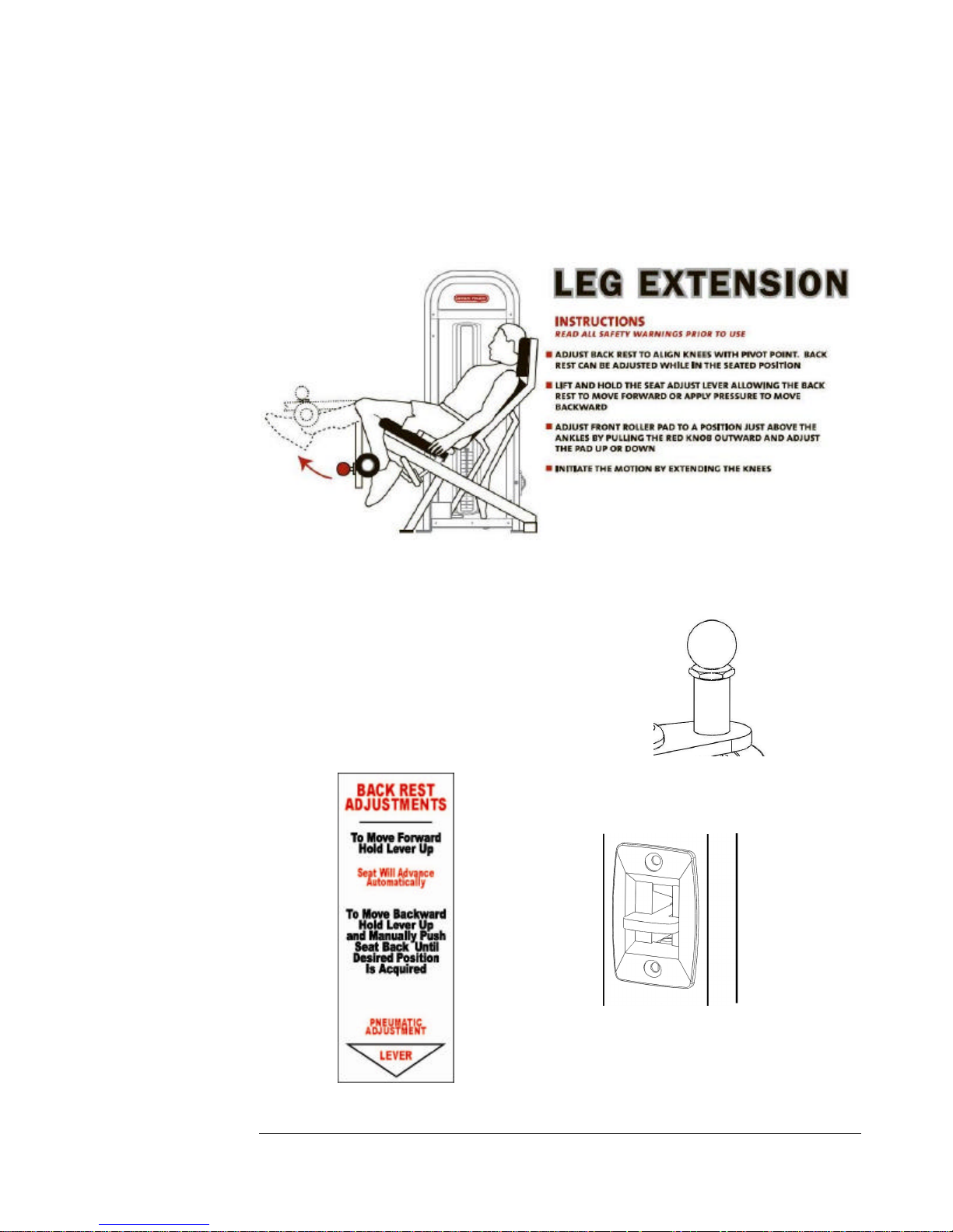
Leg Extension (Center Mount)
• No assembly required
For both the Leg Extension and Leg Curl:
To adjust Roller Pad Position pull knob and
position pad
18
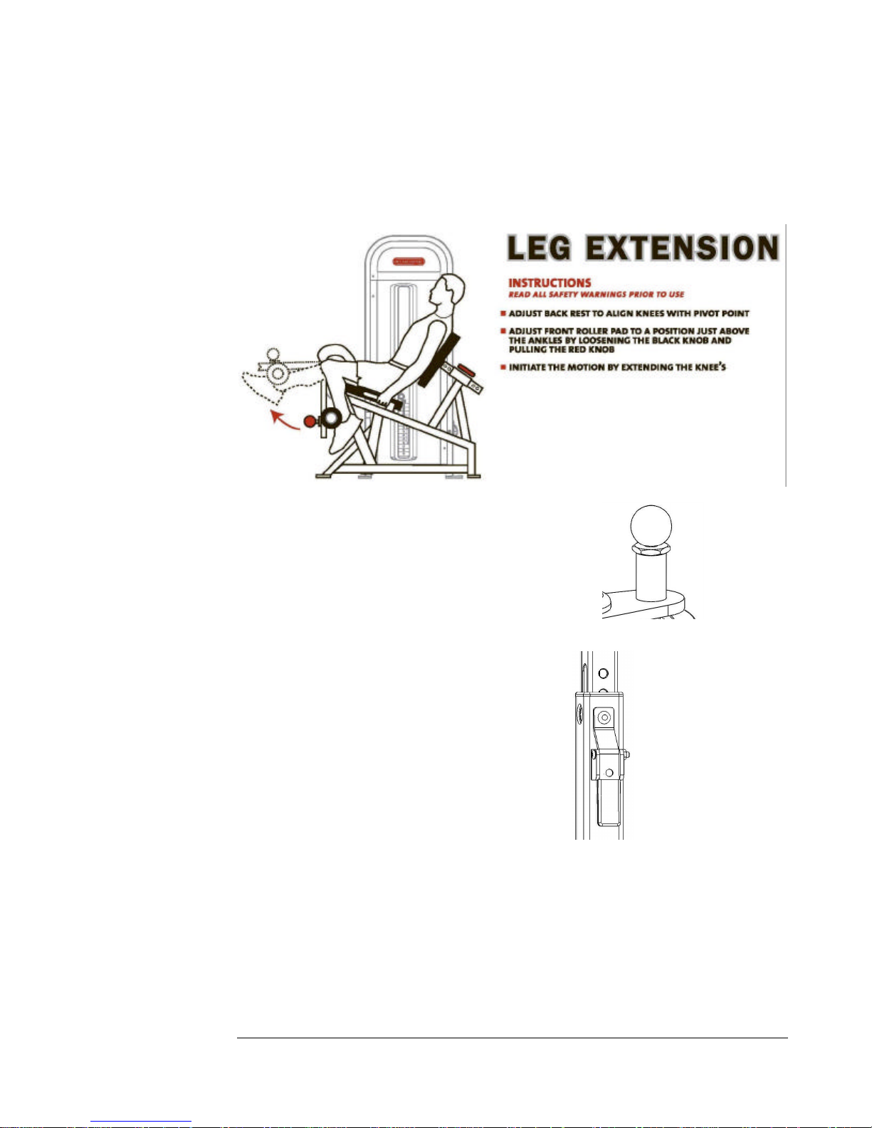
Leg Extension (Side Mount)
• No assembly required
To adjust Roller Pad Position pull knob and
position pad
To adjust Back Rest Pad
depresses lever and slide
assembly.
19

Leg Press
• No assembly required
Low Back
• No assembly required
To adjust Foot Platform pull knob and position
Foot Platform in desired location
20

Low Row
• No assembly required
Overhead Triceps
• No assembly required
To adjust seat height, depress
lever and slide assembly.
21

Pectoral Fly
• No assembly required
Seated Leg Curl
• No assembly required
22

Seated Leg Press
• No assembly required
Shoulder Press
• No assembly required
To adjust seat height, depress
lever and slide assembly.
23

Standing Calf
• No assembly required
Triceps Dip
• No assembly required
To adjust seat height, depress
lever and slide assembly.
24

Triceps Extension
• No assembly required
To adjust seat height depress
lever and slide assembly.
Unilateral Row
• No assembly required
25

Chest Press
• No assembly required
Vertical Row
• No assembly required
26

30° Pectoral Fly
• No assembly required
45° Calf
• No assembly required
27

DAP – Dual Adjustable Pulley
DAP Assembly
28

3 1
2
DAP Warning Stickers:
1. Not a Step (PN: 5220-0027)
2. Assure adjustable handle locking pin is fully engaged before exercising (PN:
5220-0031)
3. Use only authorized attachments shipped with product (PN: 5220-0026)
Adjust Handle/Roller/Pulley Assembly by pulling Red Handle away form guide rod to
disengage Locking Pin, Move assembly up or down the guide rod to desired position
and let go of handle to allow pin to engage hole in guide rod. Assure pin is fully
engaged in hole prior to starting exercise.
29

Chapter
W
Transmission Source
Replacement
Transmission Sources
STAR TRAC STRENGTHTM utilizes several types of transmissions sources; these
sources may include some or all of the following components. Cables, Belts,
Cams, Pulleys, Tie Rods, Flange Bearings, Pillow Blocks and Rod Ends. These
components should be checked and lubricated on a regular bases where applicable.
General Guidelines
orn belts and cables can be dangerous. Unexpected failure of a
transmission source can result in injury to the user and/or by-stander.
It is the responsibility of owner and/or the person managing the
goodwill of the product to frequently inspect transmission source(s) for loose
fittings and/or wear areas. Replace cables and belts at first sign(s) of wear. When
replacing and/or tightening a transmission source, be certain to check that
connection(s) are tight.
The life of any transmission source is conditional to use. Each facility is different
and as a result, STAR TRAC STRENGTHTM cannot “estimate” the life of any one
transmission source. Therefore, this responsibility must be managed at the site of
the facility.
When tightening or changing cables,
termination bolt should never exceed ¾” thread
exposure. This is the inside measurement
between lock nut and head of bolt. Check and
adjust accordingly and be certain that lock nut is
tight. The tool needed for this procedure is a
¾” box wrench.
30

Belts - Fasteners
When tightening or changing belts, there are three securing systems STAR TRAC
STRENGTHTM utilizes which you should be familiar with.
1. Synch Fastener
This is found on all top plates. When changing a belt which connects to a weight
stack, this is normally the first of the two connection sources which you will
tighten and secure. The tool required for this application is the ¼” Allen wrench.
There are two types of Synch Fastener systems on Start Trac Strength Equipment
refer to Appendix A for a description of the two types and Torque specifications
for each.
2. Compression TP Fastener
This is found on all cams and drive systems. When changing any belt, this is
normally the first of two connection sources which you will tighten and secure.
The tool require for this application is the 3/8” Allen wrench.
31

3. Compression Swivel Fastener
This is only found on the termination end for Lat Pull, Low Row and occasional
Triceps pushdown applications. The tool required for this application is the 1/8”
Allen wrench.
4. Compression Cam Fastener
This is found on all cams and drive systems. When changing any belt, this is
normally the first of two connection sources which you will tighten and secure.
The tool require for this application is the 3/16” Allen wrench.
32

Belts - Replacement Procedures
Attaching Belt to Top Plate (Synch Fastener)
1. Belt clamp must first be removed. To do so, loosen Allen head bolt on
top of Synch Fastener and back out only far enough so belt clamp may
be removed. (It is not necessary to remove this bolt).
2. Once belt clamp insert has been removed, slide belt through slot in
Synch Fastener.
3. Allow belt end to surface approximately 1” above Synch Fastener.
Hold the end of belt and push down on opposing side of belt so belt
will lay flat against bottom of belt clamp.
4. Note machined female receptacle in belt clamp insert. This receptacle
must be aligned vertically and on center of Synch Fastener so that Allen
head bolt may be properly seated.
5. Once in place, be certain to keep belt straight while tightening Allen
head bolt into belt clamp insert. (Refer to Appendix A “Synch
Fastener Torque Specs,” for detailed instructions.)
Note: Misalignment of belt may bias the top plate, which can cause center post to
abrade (clanging) weight plates below, causing center post and top plate to not
properly seat. This result poses the possibility of injury to user and/or by-stander
to exist.
Attaching Belt to Swivel Appliance (Compression Swivel Fastener)
1) With ¼” shoulder bolt removed, take end of belt and measure 2 and
½” and fold belt 180 degrees. The belt utilized for Lat Pulls and Low
Rows is a composition of multi layered nylon and will be difficult to
33

fold. Utilizing a blow dryer to temporarily soften nylon will help to
achieve end result.
2) With belt at 180 degrees, insert belt into swivel casing pushing loop
slightly beyond the ¼” hole and insert ¼” shoulder bolt.
3) With 3/16” Allen wrench, tighten shoulder bolt into casing.
Remember to tighten lock nut against shoulder bolt.
4) Locate sleeve bolt holes and insert both compression sleeves on either
side of belt making sure to align compression sleeves with bolt holes.
5) Insert ¼” tightening sleeve
bolts on either side of swivel
casing and begin to tighten.
Belt must remain on center of
swivel casing therefore,
tightening of bolts must
alternate back and forth until
each bolt has reached 200 inch
pounds. Do not tighten in a
circular manner.
Attaching Belt to Drive Systems (Compression Fastener)
1) Loosen the 3/8” Allen head bolt so that the compression clamp will
able to move freely.
2) Wrap belt around inner barrel so that the end of the belt is between the
cam and the outer belt.
3) Place clamp over belt and tighten. Tighten 3/8” Allen to
approximately 320 inch pounds.
3/8” Allen
Clamp
Belt Barrel
34

Belts - Installation
Observe the three types of belt clamps used on the STAR TRAC STRENGTHTM
in your facility as well as the cable applications and familiarize yourself with the
type(s) you will be working with.
Review all routing and belt clamps for the machine you are working on.
First, remove old belt, once removed, sandwich old belt to new example belt to
establish actual length belt needed by trimming off excess. Belt can be trimmed
by using commercial grade scissors or utility knife.
Once trimmed to desired length, route the new belt and begin securing process to
fasteners. Note: Route the belt as shown in the appropriate belt routing diagram.
Securing belt will vary depending upon application of transmission source.
Cables
There are four types of applications in which STAR TRAC STRENGTHTM
products utilize cables as a transmission source.
Type 1. Terminal / Swedge Fitting
Double Termination Smith Cable
When changing cable(s) on the STAR TRAC STRENGTHTM Smith Machine, first
and after removing old cable, take one end of (terminated) cable, place one drop
of Loctite onto threads and begin to tighten (clockwise) bolt into counter balance
(CB) until tight. This will require one ½” open-end wrench. Next, securely place
Olympic bar onto third hook (from top). Following this, with adjustable “Vice
Grips” establish setting on tool that will firmly lock grips around the 5/8” O.D.
vertical shafting which allows C.B. to travel. Once the setting for Vice Grip has
been set, lift C.B. 19” from inside of frame to bottom of C.B., place Vice Grip
underneath C.B. and clamp securely. Should Vice Grip not be tight enough, C.B.
may drop therefore; keep hands and feet from underneath C.B. Next, run cable
up and around the two overhead 4” pulleys and down to bearing assembly where
you will terminate end of cable by tightening cable into Smith Machine bearing
assembly. As with other termination end, before tightening, place one drop of
Loctite onto threads and then commence to tighten bolt head. Lastly, with both
cable ends secure, raise bar enough to clear hooks make sure cable is seated in
35

both overhead pulleys and then, slowly allow Olympic bar to descend and lock
onto next lower setting. By doing so, this process will raise C.B. at which point
you can unlock Vice Grip from shaft.
Triceps Pushdown Station(s)
Take termination end of cable and thread (push in and over) it through upper
pulley and down to weight stack. Before threading into center post, make sure
lock nut is at least, ½” above end of termination bolt. Then, place one drop of
blue “Loctite” on end of the threads of termination bolt. Clockwise, screw
termination bolt into center post. By pre measuring lock nut, you will be assured
that termination bolt has seated at least, ½” inside center post. Lastly, tighten lock
nut (turn clockwise) against center post. In addition to the “Loctite” by
tightening lock nut against center post will help to keep termination bolt from
loosening. Be certain that cable is properly seated in groove of upper pulley and
that cable hangs vertically without signs of bias or entanglement.
Adjustable Cross Over Cable(s)
Take termination end of cable and thread between pulleys (adjustable housing),
down and around low pulley to adjacent pulley residing directly under weight
stack. Next, bring cable up to high pulley thread (180 degrees) around and then
down to thread (180 degrees) around pulley residing on top plate, back up to
second high pulley where again, you will thread (180 degrees) cable around and
down into mounting plate on adjustable housing. When tightening termination
end, it will require an examination of cable tautness. Cable should deflect
approximately 1” +/- from center without raising top plate. To tighten, place
tightening nut at top of termination so that proper adjustment can be established.
Next, push termination end into hole of mounting plate until satisfactory cable
tautness has been achieved. Next, spin down tightening nut until it rests on
mounting plate. Lastly, with 3/8” open end wrench, secure termination end and
36

begin screwing ½” lock nut (will require ½” box wrench) onto termination thread
ends and begin tightening. When tight, keep box wrench on nylon locking nut
and take an open end ½” wrench and tighten down lock nut. When complete,
once again check for cable tautness. Should the cable be too tight, top plate may
rise above 2nd plate which will not allow weight stack pin to properly seat making
weight stack inoperative.
Low Swivel Station(s)
Take termination end of cable and thread under low pulley (between pulley and
guard) and follow around and continue pulling cable up to upper pulley and thread
cable through and around and down, to weight stack. Before threading into center
post, make sure lock nut is at least ½” above end of termination bolt. Then, place
one drop of blue “Loctite” on end of threads of termination bolt. Clockwise,
screw termination bolt into center post. By pre measuring lock nut, you will be
assured that termination bolt has seated at least, ½” inside center post. Lastly,
tighten lock nut (turn clockwise) against center post. In addition to the “Loctite”
by tightening lock nut against center post will help to keep termination bolt from
loosening. Be certain that cable is properly seated in groove of both pulleys and
that cable hangs vertically without signs of bias or entanglement.
37

SET SCREW
Cross Over Cables (Non Adjustable)
Like the STAR TRAC STRENGTHTM adjustable Cross Over Cables, this cable also
has a termination and swedged loop end. The termination end once threaded through
the pulleys, will also receive a loop end however, for assembly and/or replacement
reasons, it has been manufactured and designed with a termination end. First,
straighten cable to reduce bias in the cable. Take termination end and feed through
lower pulley continue up and behind weight stack shroud and up to high pulley (as
shown in diagram) then, reverse direction 180 degrees back down to pulley on weight
stack (as shown in diagram) and again, reverse direction 180 degrees to upper swivel
pulley and feed through and around. With selector (weight stack) pin unengaged, grasp
cable termination end and feed rubber ball through. Next, screw on lock nut against
rubber ball and place one drop of Loctite onto end of thread. Once this is done,
screw on cast swedge fitting (loop end) until end of fitting clears 1/8” pilot hole at end
of termination bolt. Use 9/16” open-end wrench to lock down lock nut against
swedge fitting. So that these appliances may be properly tightened, it will be necessary
to secure swedge fitting with either Vice Grips or screwdriver (as shown in diagram).
Once tight, feed cotter pin through pilot hole and wishbone ends. Upon completion,
inspect cable to insure it is properly seated inside groove of all pulleys and free of any
encumbrances.
38

Chapter
Frame and Upholstery
Management
Framework Maintenance
All STAR TRAC STRENGTHTM frameworks should be wiped down on a daily
basis. By doing so, it will not only improve the longevity of your finish(s) but aid
in identifying fatigue cracks in a frame or component, loose bolts, worn cables or
belts and other area’s which may require attention.
Frames and components can be wiped down with a damp cloth daily. Every three
to four months, utilize an easy application car wax. This (wax) protection may
preserve the powder coating from premature rusting due to corrosives found in
perspiration and allow loose particles to be more easily removed when simply
wiping your product down with a damp cloth. Do not use lacquer thinner,
acetone and/or other solvents. These chemicals will dull and possess agents
which may remove the epoxy based powder from the frame.
To repair a scratch or chip on a frame or component, first determine the severity
of the damage. Some scratches can be removed with an automotive rubbing
compound. A scratch which is too deep to rub out, like a chip, can be filled with a
“touch-up” bottle from the STAR TRAC STRENGTHTM parts department.
Typically, solid colors are the easiest to repair in contrast to textured powders. To
touch-up, you will need a color-matched paint from the STAR TRAC
STRENGTHTM parts department. Fill area in sparingly. Two coats are better than
one heavy coat. Once area is dried, aesthetic choices as to its finishing are
optional. The repair can stand-alone or, efforts to blend and color sand the repair
can be attempted. This process is a difficult one and should be practiced by
someone knowledgeable in this field.
39

Upholstery Maintenance
Due to corrosive agents in perspiration, upholstery should be cleaned daily with a
10% diluted consistency of lanolin hand cleaner in warm water. Do not use
products such as Lysol, Armoral, Windex or other abrasive detergents as they
will dry out and eventually cause Naugahyde to prematurely crack. When
cleaning upholstery, wipe down top and sides with solution and follow up with a
dry towel to remove residue(s).
Replacing upholstery pad(s) and protective wear guard(s): To replace or remove
any STAR TRAC STRENGTHTM upholstery pads will require a single 5/16” box
or socket head wrench and flat blade screw driver.
For those pads which incorporate the (black sheathed) corrosive resistant cap, take
flat blade screwdriver and wedge blade underneath cap and twist. This action will
remove cap and expose ½” bolt assembly. Next, loosen and remove all bolts
which secure pad to frame assembly. Each bolt is accompanied by one sae washer
and “retainer clip.”
Replacement of upholstery pads is just as simple. Line pad up with hole(s) in
frame and begin hand tightening one at time until all bolts are snug. Before
tightening, check that pad is properly positioned (linear to frame work), and begin
tightening bolts. Once tightened, replace corrosive cap(s).
For those upholstery applications which involve a protective wear guard, the
application of removal and assembly is the same.
40

Chapter
Warranty Information
Warranty & Disclaimer.
STAR TRAC STRENGTHTM warrants all frameworks for a period of
10 years. All moving parts are warranted for 1 year. 10 year limited
warranty on structural frame not including coatings. 90 days on
upholstery stitching only, cables and belts. Warranty is for parts only.
Warranty is good and available to the original purchaser only as noted
by STAR TRAC STRENGTHTM invoice and is not transferable nor
assumable. STAR TRAC STRENGTHTM cannot warrant products
that have been abused, neglected and or poorly maintained. All
equipment should be reviewed at the time of delivery for damage,
breakage, loosening of nuts and bolts, components and or any other
moving parts. Any and all claims for warranty must be received in
writing within 70 days of defect. Do not alter, modify or redesign any
STAR TRAC STRENGTHTM products or use any replacement parts
or materials other that those components original to STAR TRAC
STRENGTHTM as it will limit the warranty and liability of STAR TRAC
STRENGTHTM. STAR TRAC STRENGTHTM reserves the right to
change, replace or modify products, parts, accessories and or design
without notice. Deposits on cancelled orders will be subject to handling
and restocking charges.
WHAT IS COVERED
This STAR TRAC STRENGTHTM commercial exercise equipment (Product.) is
warranted to be free of all defects in material and workmanship.
WHO IS COVERED
The original purchaser or any person receiving the Product as a gift from the
original purchaser.
41

WHO PAYS TRANSPORTATION & INSURANCE FOR SERVICE
If the Product or any covered part must be returned to a service facility for repairs,
We, STAR TRAC STRENGTHTM, will pay all transportation and insurance
charges for the first year. You are responsible for transportation and insurance
charges for all subsequent years.
WHAT WE WILL DO TO CORRECT COVERED DEFECTS
We will ship to you any new or rebuilt replacement part or component, or, at our
option, replace the Product. Such replacement parts are warranted for the remaining
portion of the original warranty period.
WHAT IS NOT COVERED
Any failures or damage caused by unauthorized service, misuse, accident,
negligence, improper assembly or installation, debris resulting from any
construction activities in the Products environment, rust or corrosion as a result of
the Product(s) location, alterations or modifications without our written
authorization or by failure on your part to use, operate and maintain the Product
as set out in your Owners Manual.
OWNERS MANUAL
It is VERY IMPORTANT THAT YOU READ THIS MANUAL before
operating the Product. Remember to perform the periodic maintenance requirements
specified in the Manual to assure proper operation and your continued satisfaction.
How to Get Parts & Service
Simply call Customer Support at (800) 503-1221 or visit us on the web at:
http://support.startrac.com/Services
Before shipping:
1. Obtain a Return Authorization Number (RMA#) from Customer
Support Services
2. Securely pack your Product (use the original shipping carton, if
possible)
3. Write the RMA# on the outside of the carton
4. Insure the Product, and
42

5. Include a letter explaining the defect or problem and a copy of your
proof of purchase if you believe the service is covered by warranty
EXCLUSIVE WARRANTY
THIS LIMITED WARRANTY IS IN LIEU OF ALL OTHER WARRANTIES
OF ANY KIND EITHER EXPRESSED OR IMPLIED, INCLUDING BUT
NOT LIMITED TO THE IMPLIED WARRANTIES OF
MERCHANTABILITY AND FITNESS FOR A PARTICULAR PURPOSE,
AND ALL OTHER OBLIGATIONS OR LIABILITIES ON OUR PART. We
neither assume nor authorize any person to assure for us any other obligation or
liability concerning the sale of this Product. Under no circumstances shall we be
liable under this warranty, or otherwise, of any damage to any person or property,
including any lost profits or lost savings, for any special, indirect, secondary,
incidental or consequential damages of any nature arising out of the use of or
inability to use this Product. Some states do not allow the exclusion or limitation
of implied warranties or of liability for incidental or consequential damages, so the
above limitations or exclusions may not apply to you.
CHANGES IN WARRANTY NOT AUTHORIZED
No one is authorized to change, modify or extend the terms of this limited
warranty.
EFFECT OF STATE LAWS
This warranty gives you specific legal rights and you may have other rights, which vary,
from state to state.
OUR PLEDGE TO YOU
Our Products are designed and manufactured to the highest standards.
STAR TRAC STRENGTHTM wants you completely satisfied with our Products
and will do everything possible under the terms of this warranty to keep you
secure in knowing you have bought the best!
43

Chapter
Preventative Maintenance
DAILY
• Clean
o Upholstery with a mild soap and water.
o Guide rods with a cotton cloth and break-free.
o Hand grips with mild soap and water.
• Inspect
o Cables for wear or damage and proper tension (should not
exceed 3/4" deflection). Pay close attention at bends and
attachments points.
o Hardware should be checked for looseness. Tighten as
required using the proper tools.
o Frames should be inspected for wear or damage.
o Handgrips should be checked for wear or damage.
• Perform
o Wipe down upholstery with a mild soap and water or
comparable all purpose cleaner.
o Visually inspect belts and/or cables for wear at and around
connections and along entire length of belt and/or cable.
Always replace at first sign of wear.
44

! WARNING: Replace all worn cables immediately. The following
conditions indicate some types of wear.
Torn or Cracked Cable Sheath that exposes cable
Stretched cable sheath
A Kink in the cable
45

! WARNING: Replace all worn belts immediately. The following
conditions indicate some types of wear.
Belt Tear
Belt Cords Exposed
Edge Wear
46

Attachment Hole
! WARNING: Replace all worn handles immediately. Do Not use if less than
1/8” of material remains on the edge of attachment holes.
WEEKLY
• Visually inspect all hardware for loosening, tampering or wear.
o Refer to Appendix C for DAP Handle instructions
• Check jam nut on weight stack for tightness.
• Inspect all accessory and or carabineer clips or connecting links for wear.
• Check condition of handgrips.
• Check cables for stretch and adjust as necessary by loosening the large nut on top
of the weight stack and screw in the threaded plug until cable is tight and the
weight stack pin goes in all holes easily. Tighten the large nut to complete the
adjustment.
• Lubricate Guide Rods
o Refer to Appendix B for instructions
47

MONTHLY
• Clean Guide Rods with break-free on a cloth and wipe off old residue.
Clean tops of bearings at stack and inspect for heavy buildup on rods
below head plate (lift half of stack and do a visual inspection, then
clean as necessary).
Notes
• Use polishing compound (such as car wax) to clean and remove shoe
scuffs from powder coated surfaces as necessary.
Clean the Shrouds
• The shields on the Platinum Series machines are made from
POLYCARBONATE. Adherence to regular and proper cleaning
procedures is recommended to preserve the appearance.
• Impact are ABS clean with the following
Washing to Minimize Scratches
Wash POLYCARBONATE with a mild soap or detergent (e.g. Original Dawn
Dishwashing Liquid) and lukewarm water using a clean sponge or a soft cloth.
Rinse well with clean water. Dry thoroughly with a chamois or moist cellulose
sponge to prevent water spots. Do not scrub or use brushes on these products.
Fresh paint splashes, grease and smeared glazing compounds can be removed easily
before drying by rubbing lightly with isopropyl. Afterward, a warm final wash
should be made, using a mild soap or detergent solution and ending with a
thorough rinsing with clean water.
Some Important Reminders
• DO NOT use abrasive or highly alkaline cleaners on the shields.
• Never scrape shields with squeegees, razor blades or other sharp
instruments.
• Benzene, gasoline, acetone or carbon tetrachloride should never be used on
the shields.
• DO NOT clean shields in hot sun or at elevated temperatures.
48

Compatible Cleaners for Shields
The following cleaning agents have been found compatible with
POLYCARBONATE. The manufacturer's recommendations and instructions
should be followed. They are Original Dawn, Freon T.F., Palmolive Liquid,
Top Job, and Windex with Ammonia D.
Removal of Paint, Marking Pen, Labels
Butyl cellosolve works well for removal of paints, marking pen inks, lipstick,
etc. Labels, stickers, etc. may be removed using kerosene. When the solvent
will not penetrate sticker material apply heat (hair dryer) to soften the adhesive
and promote removal. GASOLINE SHOULD NOT BE USED.
49

Chapter
Sticker Part Numbers
PN: 5220-0001
8 ½ x ¾
PN: 5220-0002
4 3/8 x ¾
PN: 5220-0003
8 ½ x ¾
PN: 5220-0004
4 3/8 x ¾
50

PN: 5220-0005
3 x 1 ½
PN: 5220-0009
7 x 1 ½
PN: 5220-0010
3 x 1 ½
PN: 5240-0001
1 ½ x 4
51

PN: 5220-0011
5 x 3
PN: 5220-0013
3 x 5
PN: 5240-0002
4 x 1 1/2
52

PN: 5240-0003
2 @ 1 ½ x 6 ea.
PN: 5240-0004
16 x 1 ½
PN: 5240-0005
3/4 x 12
PN: 5240-0006
5/8 CIRCLES
53

PN: 5220-0015
5 x 3
PN: 5220-0017
7 x 1 ½
PN: 5220-0018
7 x 1 ½
PN: 5240-0008
1 ½ x 11
54

PN: 5240-0009
2 @ 1 ½ x 4
PN: 5240-0010
3/8 x 6 ¼
PN: 5240-0011
3/8 x 6 ¼
55

Appendix
Appendix A: Synch Fastener Torque
Specifications
Synch Fasteners using threaded barrels torque specification is 350-400 in-lbs.
56

Synch Fasteners using T-nut torque specification is 125-135 in-lbs.
T-Nut
**It is recommended that the T-nut be replaced after the third time of being retorqued.**
Note: If synch fasteners are not torqued within the recommended specifications
as stated above, damage may occur to the machine which could result in injury to
the user.
57

Appendix B : Guide Rod Lubrications
Procedure
There are two different types of weight stacks: One weight stack type uses the
Lock-N-Load (LNL) technology and has a shorter shroud. The second weight
stack is a typical weight stack that uses a weight pin with bungee cord. Both weight
stacks can be lubricated with ‘3-IN-ONE’ oil that can be applied in the same
manner.
Step 1: Removing Shroud Cover
Remove the shrouds by using the screwdriver (Fig. 1).
Note: Do not use a cordless drill to reinstall shroud. Cracking may occur when
tightening the screws.
Fig. 1 Fig. 2
The shroud in Fig. 2 uses on our LNL technology weight stack. This shroud does
not need to be removed to apply oil to the guide rods. The only time this shroud
needs to be removed would be to tighten or replace the guide rod collars.
Step 2: Inspecting guide rod collars
Once the shroud has been removed, check the guide rods for wear or looseness.
Check the location of the guide rod collars. Adjust them by tightening the two set
screws on each collar.
58
CORRECT INCORRECT
Fig. 3 Fig. 4
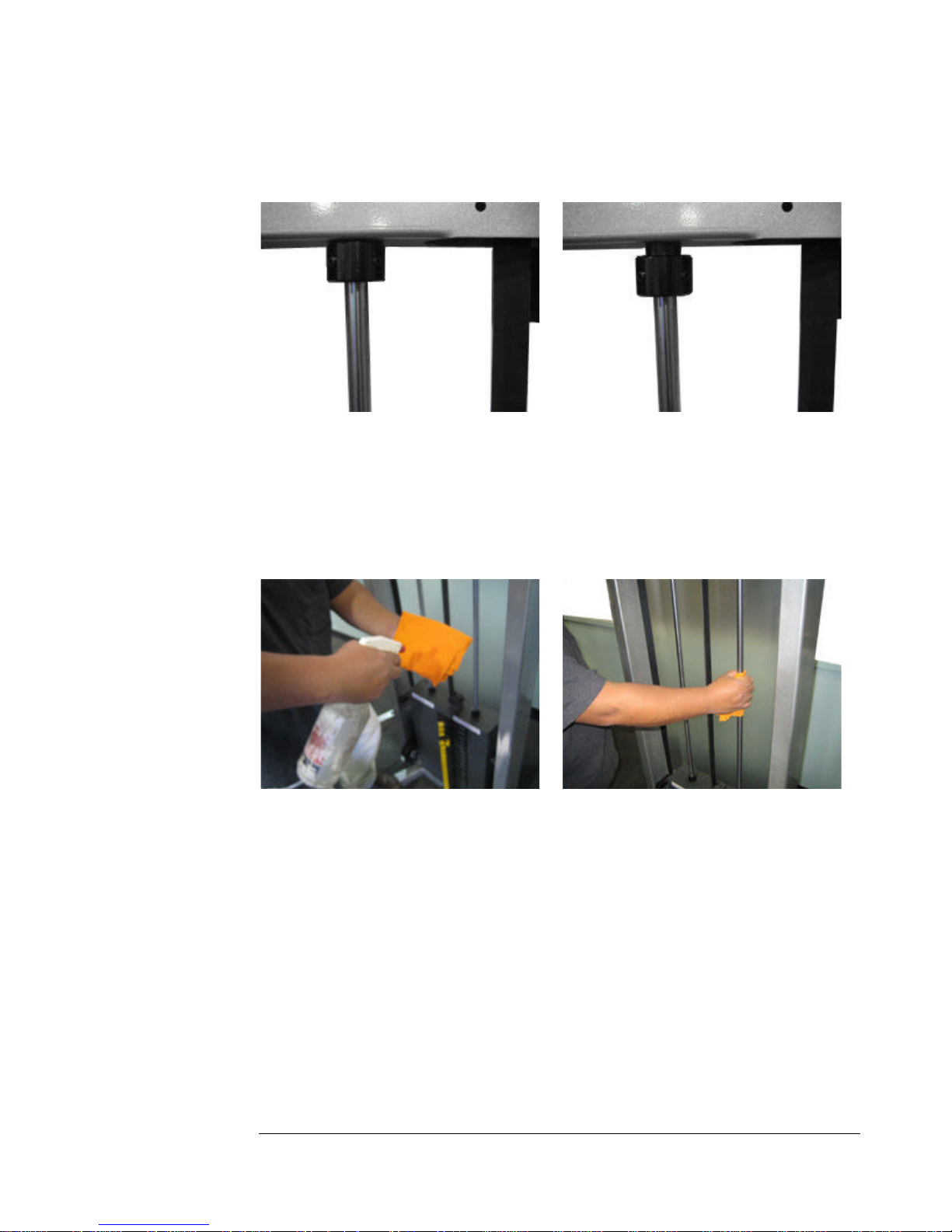
Step 3: Cleaning the guide rods
Apply alcohol directly onto a clean cloth or rag (Fig. 5). Clean each guide rod by
using an up and down motion (Fig. 6).
Fig. 5 Fig. 6
Step 4: Re-lubricating Guide Rods
Apply ‘3-IN-ONE’ oil directly onto a clean towel or rag (Fig. 7). Avoid applying
the oil directly onto the guide rods as excess or over-splashed oil may
contaminate the belts and pulleys which may cause slipping during use.
Apply oil onto guide rods from the towel or rag using an up and down motion
(Fig. 8) making sure the guide rods are oiled all the way around and evenly. Clean
all excess oil that might have spilled or accumulated on the top plate bushing.
Once excess oil has been cleaned, test unit by lifting top plate only.
59
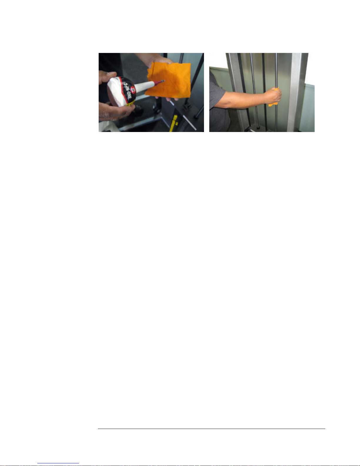
Fig. 7 Fig. 8
Final Step:
Once the Lubricating Guide Rod procedure has been performed and all safety
checks have been performed, replace the shroud by reversing the procedure in
Step 1.
NOTE:
Star Trac does not recommend using Tri-Flow, Graphite, or oils with a graphite
base on the weight plate guide rods. If any of these products have been used in the
past, Star Trac recommends thoroughly cleaning guide rods and re-lubricating
with ‘3-IN-ONE’ oil as soon as possible.
It is recommended to perform this procedure on a weekly basis to ensure peak
performance of your Star Trac StrengthTM product.
60

Appendix C: DAP handle inspection
and tightening procedure
Tools Required
o 5/32” Hex key wrench
o 7/16” Open end wrench
Step 1 - The first step is the inspection of the adjustment handle (Fig.1), this is
performed by grasping the red handle and attempting to wiggle the adjustment
handle. If the adjustment handle feels sloppy or moves side to side excessively
then complete steps 2 - #. If the adjustment handle feels tight and operates
smoothly you are done.
Step 2 - If you find that your adjustment handle has excessive play then you
will need to adjust the rollers found inside your adjustment handles. Using
your 5/32” hex key and 7/16” wrench loosen the two ¼-20” button head
bolts and corresponding ¼-20” acorn nuts (Fig.2, Point A).
Step 3 - Use the head of the recently loosened ¼-20” button head and
corresponding ¼-20” acorn nut to push roller against adjustment tube. Keep
pressure on roller as you retighten the ¼-20” button head bolt and
corresponding acorn nut.
Step 4 - After completing the adjustment of the two rear rollers on both
adjustment handles ensure that all bolts on your adjustment handles are tight.
Now move the adjustment handles up and down the adjustment tubes to
verify smooth operation.
61

Figure 1 Figure 2
IF YOU HAVE ANY QUESTIONS OR CONCERNS
PLEASE CALL CUSTOMER SERVICE @ 1-800-503-1221
62
 Loading...