

STAR TRAC FITNESS S-TRx, S-TRc Install Manual
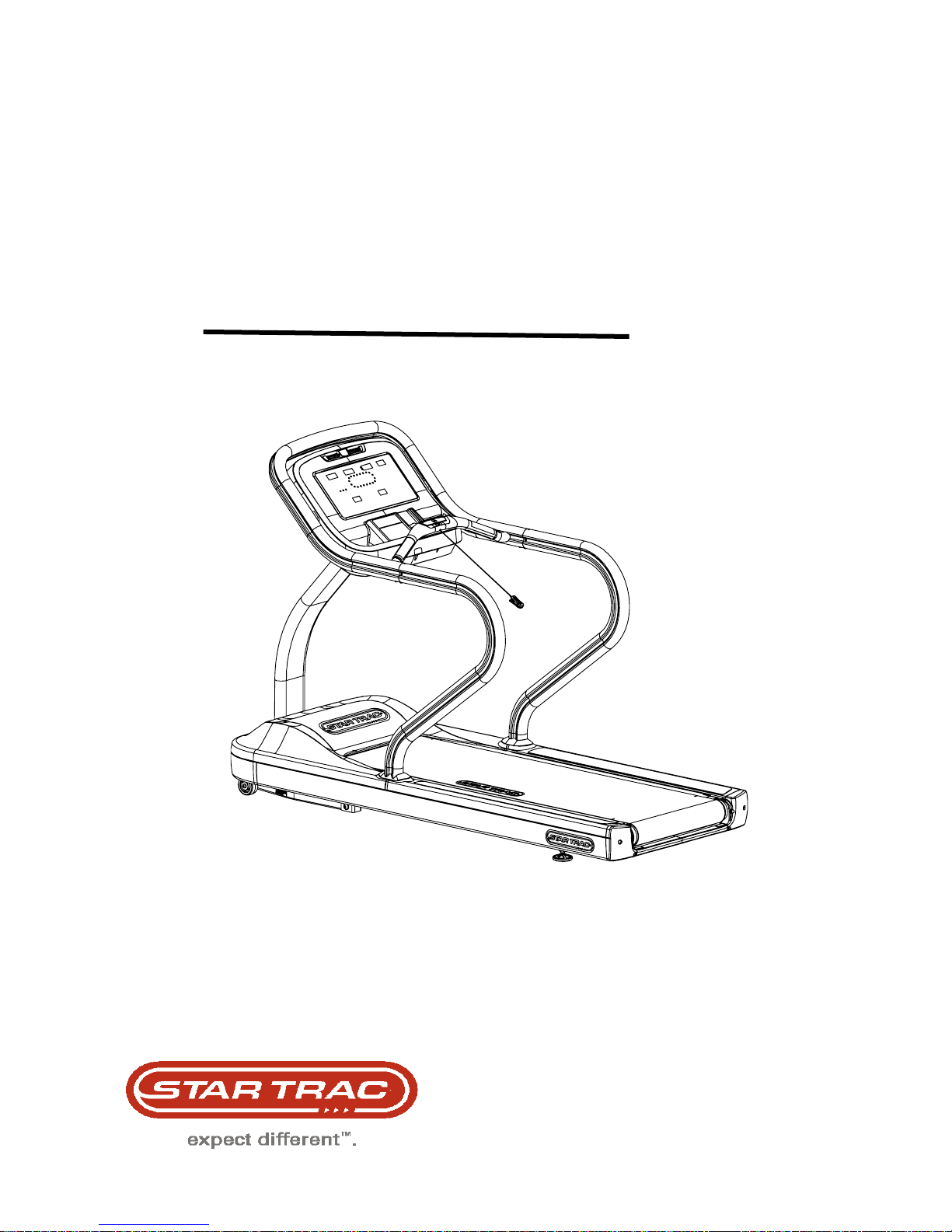
Star Trac Fitness™
S-TRx Treadmill
S-TRc Treadmill
Install Guide
ASSEMBLY AND SETUP
Use the following procedures to unpack and assemble your STAR TRAC S SERIES TREADMILL. Assembly procedures
are the same for all S SERIES TREADMILLS.
UNPACKING
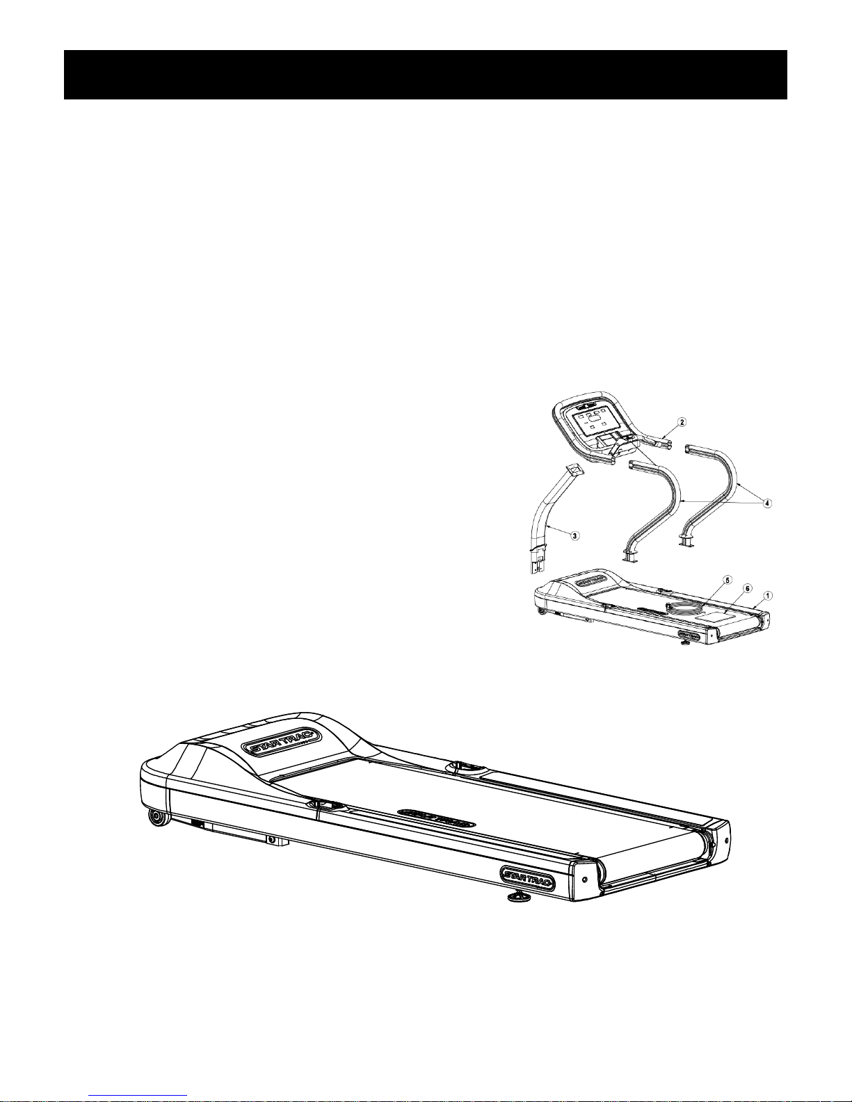
Open the shipping carton, remove all parts from the carton and foam inserts, and verify that the following parts are included
in your shipment:
Main Subassemblies Description Qty
1. Base Assembly 1
2. Display Console Assembly 1
3. Neck (and Grommet) 1
4. Handrail (and Grommet) 2
5. Power Cord 1
6. Manual and Warranty Card 1
n/a Hardware Kit 1
Hardware Kit Description Qty
Screw 5/16"-18 x 1 3/4" 4
Washer, Lock, 5/16" 16
Washer, Flat, 5/16" I.D. x 1/2" O.D. 16
Screw 1/4"-28 x 3/8", Button Head 4
Screw 5/16"-18 x 1", Socket Head 12
Screw #10-16 x 1/2" Tapping Pan Head 6
Screw M4 x 0.7 x 19mm, Pan Head 14
TOOLS REQUIRED
Most STAR TRAC treadmills can be assembled using the following tools:
• 1/4” Hex Key (included)
• 5/32” Hex Key (included)
• #2 Phillips Head Screwdriver (included)
• Torque Wrench (not included)
ASSEMBLY
1. Unpack and Position the Base Assembly
CAUTION: The motor end of the base assembly is very heavy. It is recommended that two people lift this end when
moving the base assembly.
Remove all packaging material so the base assembly is sitting on the shipping crate platform. With a helper, lift the
base assembly from the shipping crate platform, and place it in the location where it will be used. Be sure the
selected location is level, and close to a power outlet. Remove the motor shroud for installation of the handrails.
2. Install the Neck
5/16-18 x 1 3/4” Socket Head Bolts
5/16 Lock Washers
5/16 Flat Washers
Locate the neck assembly (Qty. 1) and neck grommet (Qty 1) with console cables pre-installed inside. Remove
packing material and slide the neck grommet over the neck. Position the neck in place on the motor end of the base
assembly and secure with four 5/16"-18 x 2.0" socket head bolts, 5/16 lock washers, and 5/16" flat washers. Install all
four bolts then tighten securely.
3. Install the Display Console
Locate and position the display console on the neck, taking care not to pinch the display cable between the neck and
the console. Once the console is properly positioned, secure the console to the neck using four 5/16"-18 x 1.0" socket
head bolts, 5/16 lock washers, and 5/16" flat washers. Install all four bolts then tighten securely.
5/16-18 x 1” Socket Head Bolts
5/16 Lock Washers
5/16 Flat Washers
 Loading...