


Section 1:
Introduction
Welcome to the world of STAR TRAC. In your hands is the STAR TRAC TR 4500 Service Manual.
This manual is designed to be easy to use, providing detailed instructions on how to service and maintain
the TR 4500.
We highly recommend that you read all the applicable sections of the service manual prior to serving the
treadmill. The information on the following pages will enable you to begin easily, quickly, and safely.
Contents
1.1 How to use the Service Manual
1.2 Precautions
1.3 Product Support Assistance
1.4 Tools and Test Equipment
1.5 Treadmill Overview.
1.0

How To Use This Manual
• This Service Manual has been written to assist and instruct the repair technician on key
components for quick and efficient diagnosis of service problems.
• To assist in finding the applicable sections in the Service Manual. Each Section has a table of
contents to help locate specific symptoms and topics. Titles and major headings are located at the
top of every page.
• This manual is to be used strictly as a Maintenance manual for service and repair, not as an
owner’s manual.
• An illustrated Parts List is located at the back of this manual for identifying parts with part
numbers.
• Troubleshooting tables and Error Code Flowcharts are included for certain sections to help
diagnose the system problem and find the root cause.
1.1

Precautions
1. Always make sure that the treadmill is turned off and unplugged before starting any work, unless
otherwise noted, or when necessary for voltage testing.
2. Read each section through for NOTES before starting any work.
3. To pull apart electrical connectors, pull on the connector itself, not the wires.
4. When replacing fuses, be sure the new fuses is the correct amperage rating. Do Not exceed the
fuse amp rating. If necessary use a fuse of lower rating until the proper fuse may be attained.
5. When checking continuity at the wire connector, insert the test probe carefully to prevent the
terminals from bending.
1.2

Product Support Asistance
PRODUCT SUPPORT DEPARTMENT
STAR TRAC Product Support Department sets the industry standard in Customer Service and
Technical Assistance World Wide. Providing superior product support and customer service is at the
very heart of STAR TRAC’s business philosophy. This commitment to service has been a major
contributor to STAR TRAC’s success and growth in the worldwide fitness equipment industry.
Technical Assistance
• When purchasing a part or requesting technical assistance, please contact our Product Support
Department : CALL TOLL-FREE: 1-800-535-4634 or 800-503-1221 US and CANADA or
714-669-1660
• When placing the call, please have the following information available:
1. STAR TRAC model.
2. STAR TRAC serial number
3. Problem statement / symptom.
After Hours Voicemail Direct
• CALL TOLL-FREE: 1-800-486-4736
• When placing the call, please have the following information available:
1. STAR TRAC model.
2. STAR TRAC serial number
3. Problem statement / symptom.
4. Return phone number and contact name.
Fax Requests
• Domestic and International: Fax 714-669-0739
• When placing the fax, please supply the following information:
1. STAR TRAC model.
2. STAR TRAC serial number
3. Problem statement / symptom.
4. Return phone fax number and contact name.
5. Purchase order or reference number.
6. Part description and quantity.
7. Ship to/bill to.
Product Support Documentation Access
• Web page http://www.startrac.com/support/
• Docufacts CALL TOLL FREE 1-800-429-3228 ext. 640 US and Canada or 714-253-3878 for a list
Product Support Procedures and Bulletins.
1.3
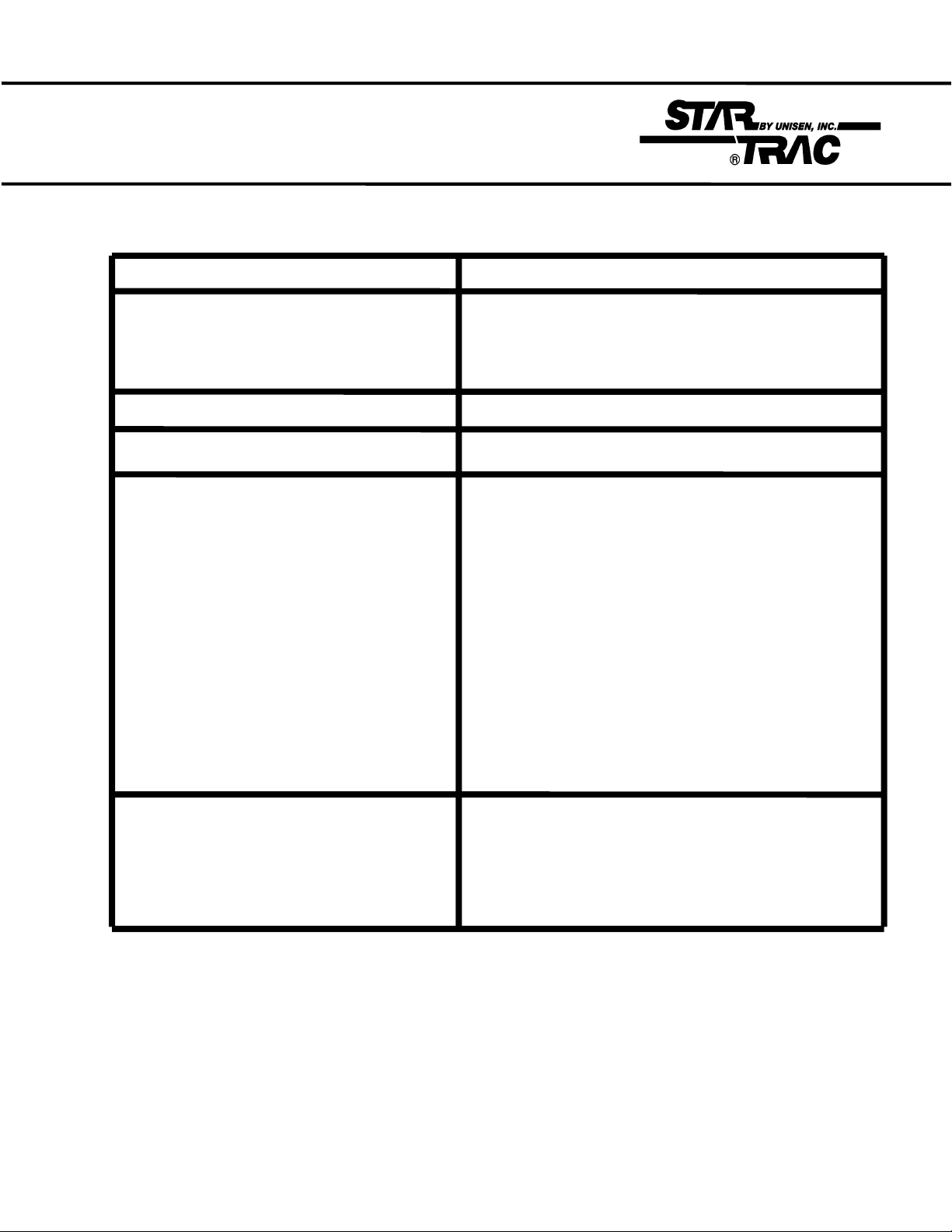
Tools and Equipment
Equipment Function
Philips Head Screwdriver #2 Shroud
Motor Control Board Assembly
Side Bed Cover and End Caps
Auto-Transformer
Small Slotted Screwdriver 3/32” Motor Control Potentiometers (MAX SPD) & (IRCOMP)
Bungee Cord 28” Suspend Motor Shroud on Display Rail
5/32” Hex Allen key Handrail assembly
5/64” Hex Allen key Display Board set screws
1/8” Hex Allen key Display Assembly
1/4” Hex Allen key Running Belt
Head Roller
Tail Roller
5/16” Wrench or Nut Driver Drive Motor Bolts
9/64” Allen Wrench Elevation Motor
17-mm Socket Wrench
Multi-meter Voltage Checks
Continuity / OHM ΩChecks
1.4
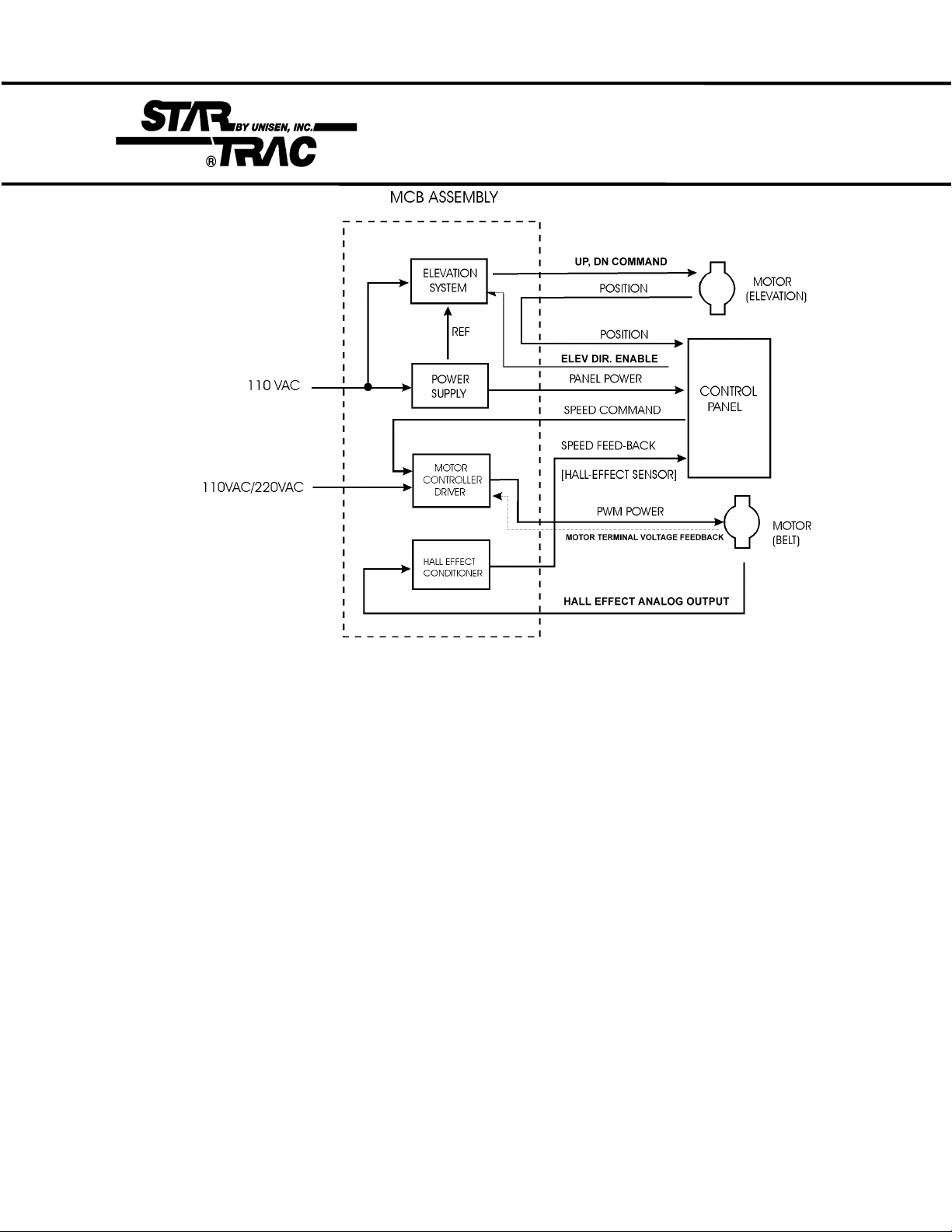
Treadmill Overview
• DC POWER SUPPLY
The MCB provides power to the display assembly. Establishes a reference voltage
and potentiameter position from the elevation motor
• RUNNING BELT MOTOR DRIVE CONTROL
Takes Alternating Current and converts it to Pulse Width Modulation
(PWM) to power the Drive Motor.
Motor voltage feedback and control-speed-commands determine the level
of PWM power delivered to the motor.
Motor Control circuits include fault sensing and safety functions.
• TACHOMETER SIGNAL CONDITIONING
The signal from the RPM sensor is fed to signal conditioning circuits on the MCB, where the signal is
converted to a digital output that is utilized by the Display Assembly to indicate belt speed.
• ELEVATION MOTOR CONTROL
The elevation circuit on the MCB receives elevation direction and enable
information from the Display Assembly, using these signals to provide
control to the Elevation Motor. Elevation position information, in turn, is
fed to the Display Assembly to indicate percent of incline.
1.5

Section 2:
Preventive Maintenance
Schedules
Performing regular preventive maintenance on all Star Trac treadmills is strongly recommended. Without
preventive maintenance, normal wear and tear may cause cumulative effects, such as misalignment and
early replacement of parts. This may result in downtime. For this reason, we highly recommend following
the manufacturer’s maintenance schedules.
Contents:
2.1 Preventative Maintenace Chart
2.2 Waxing Procedure
2.0

Preventive Maintenance Chart
Maintenance Clean Inspect Lubricate Replace
Daily
Weekly
Monthly
Quarterly
Using a liquid
non-abrasive
cleaner, wipe
down the
following:
display board
handrails,
shroud, heart
rate grips.
Note: Do not
spray directly
onto the
display
board or heart
grips.
Elevate the
treadmill and
vacuum under
the unit.
Note: Unplug
the unit when
vacuuming.
Lift the motor
shroud and
vacuum
around the
motor and
electronics.
Clean and lubricate the elevtion screws.
Note: This
must be done
with the unit
unplugged and
turned off.
Inspect for wear
and tear on exterior parts
regularly,
especially under
the running belt.
Inspect the linecord plug and
cord for possible
damage or loose
connection.
Verify running
belt alignment
and tension.
Inspect the area
under the
treadmill for
obstructions.
Inspect the
display and
handrail screws
for loosening.
Inspect the
display panel
keys for wear.
Using a silicone
spray lubricate
the elevation
screws, while
the unit is
elevated.
Note: This must
be done with the
unit
unplugged and
turned off.
Wax the running
belt and deck
using Unisen
powder wax.
2.1
Quarterly Waxing
The treadmill is designed with an automatic prompt, which will display RE WAX
across the display screen every 2,000 miles or 3,000 kilometers. The procedure
below explains step-by- step how to apply wax and clear the RE WAX prompt.
Note: Apply wax
powder while
belt and deck are
still warm (from 5
to 15 minutes of
use) for optimum
benefit. The following steps are
done with the
treadmill off.
Time Required:
5 minutes
Tools Required:
1 Wax Powder Bag (Unisen)
Teaspoon
1 Clean Towel
Paint Stick or Yard Stick
Diluted All-purpose Cleaner (409)
Bristle Brush
PROCEDURE
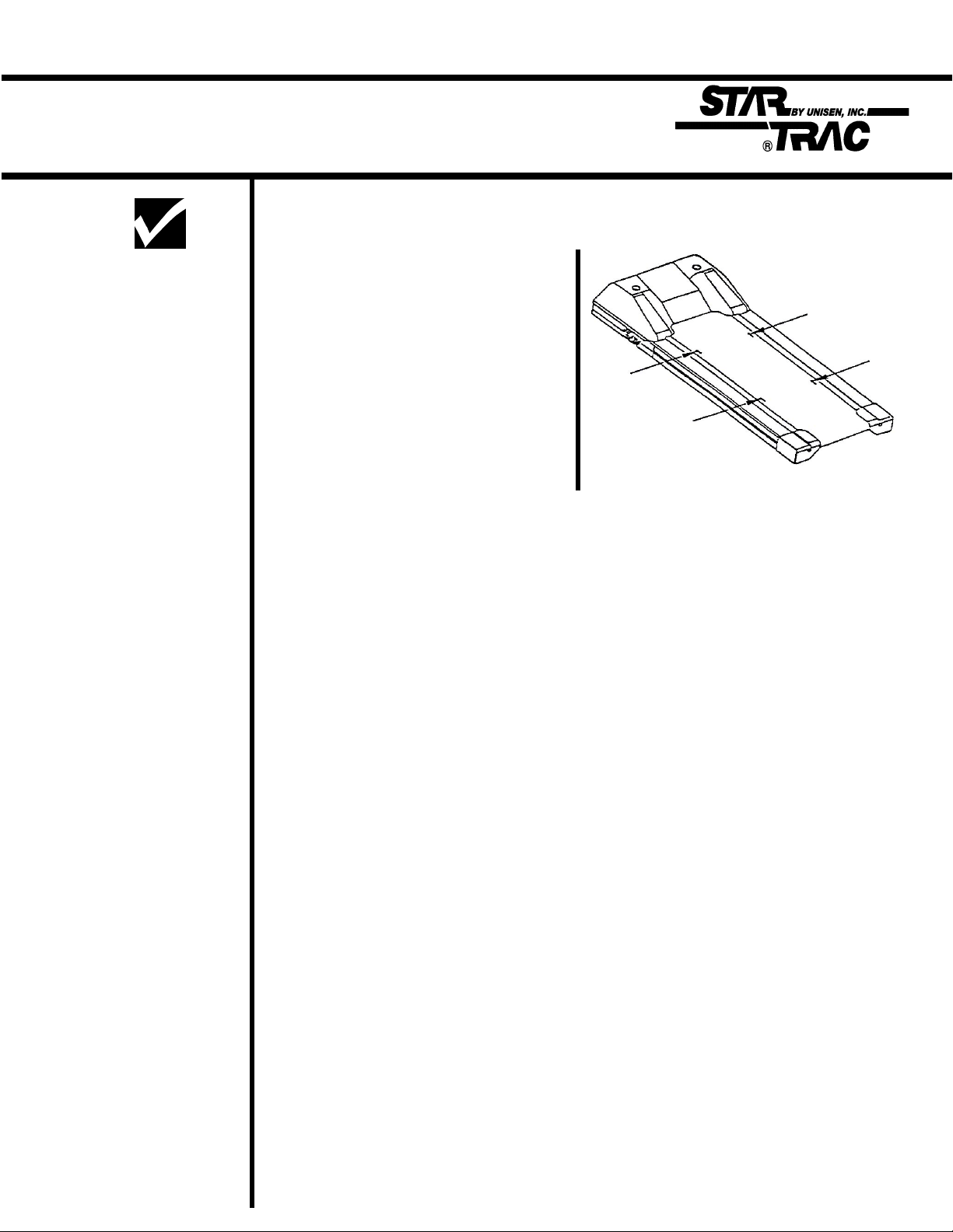
STEP 1: Cleaning the deck and belt:
• Using the stick or ruler, slide a towel under the middle of the running belt from
one side of the frame to the other.
• Hold the edges of the towel, pull from head-roller down to the tailroller, then pull
the belt down to wipe the remaining of the belt. TIP: Careful when removing the
towel, it will be dirty. Fold the dirty towel and shake into trash.
STEP 2: Re-waxing the deck and belt:
• Lift the left side (facing the display) of the belt, about 12 inches down from the
motor shroud (see above figure). Hold the belt up such that the width of the belt
is elevated from the deck.
• Gently place one level teaspoon of wax powder on the deck about two inches
from the edge, and blow the wax steadily under the belt, so that the wax powder
is spread evenly across the deck (see above figure). Gently place a second
level teaspoon of wax 18 inches down the belt.
• Repeat the above step to the right side of the belt and deck.
Note: Blow away
extra wax first
from around the
siderails and
deck before wiping.
Note: The RE
WAX prompt may
be cleared either
in “Settings or
Configure Mode”.
STEP 3: Walking the wax in:
• Start the treadmill at 1 mph and walk on all sections of the belt and deck for 1
minute to ensure the wax has been evenly distributed and worked-in properly.
STEP 4: Clean-up:
• Remove any excess wax with diluted cleaner (409) and towel, or bristle brush.
STEP 5: Clear RE WAX prompt:
• Engage Settings or Configure Modes. Press and hold the “0”, “1” or(2) &
“START” keys down, release the “1” or (2) key only. Display will beep and
display SETTINGS or CONFIGURE momentarily (depending if the 1 or 2 key
was released), then UNITS will be displayed.
• Press the Incline Down Key (elevation) until LSTDCK is displayed. Press and
release the HEART Key, this will automatically transfer the accumulated
miles/kilometers into the LSTDCK, press the ENTER Key to save.
2.2

Section 3:
Diagnostics
The STAR TRAC 4500 Treadmill series contains diagnostic and customizing modes. In these modes
you are able to check accumulated data about the past usage of the treadmill, test its motor and
display controls, and investigate display code messages. For these reasons, your treadmill is equipped
with a ;
• Manager Mode (customize)
• Maintenance Mode (diagnostics)
• Motor Test Mode (diagnostics)
Contents:
3.1 Engaging Manager Mode
3.2 Engaging Maintenance Mode
3.3 Description of parameters
• Display Test Mode (diagnostics)
• Heart Rate Test Mode (diagnostics)
3.8 Engaging Motor Test Mode
3.9 Calibration
3.10 Engaging Display Test Mode
Heart rate test
3.0
Manager Mode
After having used you Star Trac 4500 treadmill for several workouts, you may wish to specially
customize your treadmill by changing some of its settings.
To engage Manager Mode:
1. Press and hold the “ 0 ”, “ 1 ” & “ START ” keys together. While holding the “ 0 ” &
“ START ” keys down, release the “ 1 ” key only.
2. The display will beep and display Manager Mode momentarily, then UNITS will be displayed.
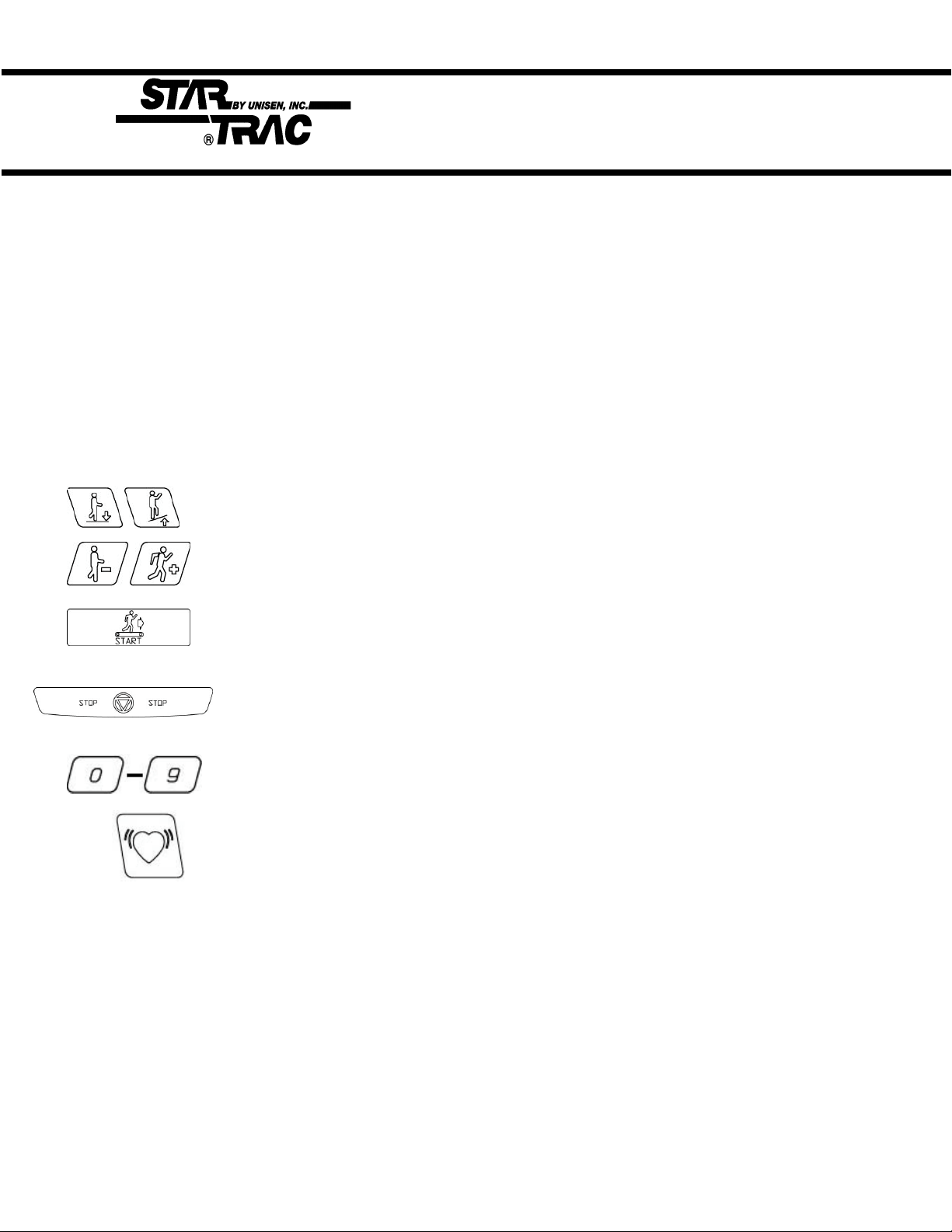
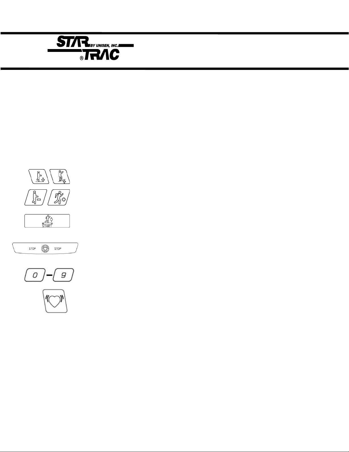
Once the treadmill is in Manager Mode, you may use the following keys:
INCLINE KEY: Displays the next or previous parameter.
SPEED KEYS: Allows the variable to be changed within the parameter.
ENTER KEY: Saves the value if changed in the EPROM (software).
Note: ENTER KEY must be pressed, for each value changed.
STOP KEY: Exists Manager Mode and restarts the treadmill with a “warm start.”
0 – 9 KEYS: Enters new parameter values. If UNITS parameter is displayed, key 5
starts DISPLAY TEST and key 8 starts MOTOR TEST.
HEART HEART KEY: When pressed will automatically display manufactures default value.
Note: ENTER KEY must be pressed, to save the default values if changed.
3.1
Manager Mode
The following parameters may be changed using the previous keys:
Parameters Lowest
Value
UNITS
MN SPD
MX SPD
EL OPT
TIME
OP HRS
--- --- English Metric English English= units of lbs.,
0.1 2.5 English=0.5 Metric=1.0 0.5 Minimum speed in
5.0 20.0 English=10.0 Metric=20.0 10.0 Maximum speed in
--- --- ON OFF ON Turns the elevation
5 99 99 Maximum time in
0 0 --- --- 6,553.5 Total operating hours
Highest
Value
Option 1 Option 2 Default
Value
Meaning
miles, hours, minutes
Metric= units of kg.,
km, hours, minutes.
MPH or KM/HR
MPH or KM/HR
system ON or OFF.
minutes allowed for
program, including
warm-up/cool-down.
DIST
WEIGHT
SER NO
LANG
ENTRY
0 0 --- --- 65,635 Total treadmill miles
(Units=English)
or kilometers
(Units=Metric)
0 399 --- --- 155 Defaults (to user),
typical weight in lbs/kg
depending on what
setting (UNITS=
English or Metric
0 0 --- --- 65,535 Treadmill serial
number.
--- --- --- --- English Language in English,
Dutch, German,
Portuguese, Spanish,
Swedish, or Italian.
--- --- Units Tenths Units This variable changes
the starting speed in
Units or Tenths
3.2
Maintenance Mode
Maintenance Mode includes all of the items of Manager Mode, plus additional data that is automatically
saved to properly troubleshoot in case of a problem. To engage Maintenance Mode:
1. Press and hold the “ 0 ”, “ 2 ” & “ START ” keys together. While holding the “ 0 ” &
“ START ” keys down, release the “ 2 ” key only.
2. The display will beep and display MAINTENANCE momentarily, then UNITS will be displayed.
Once the treadmill is in Maintenance Mode, you may use the following keys:
INCLINE KEY: Displays the next or previous parameter.
SPEED KEYS: Allows the variable to be changed within the parameter.
ENTER KEY: Saves the value if changed in the EPROM (software).
Note: ENTER KEY must be pressed, for each value changed.
STOP KEY: Exists Manager Mode and restarts the treadmill with a “warm start.”
0 – 9 KEYS: Enters new parameter values. If UNITS parameter is displayed, key 5
starts DISPLAY TEST and key 8 starts MOTOR TEST.
HEART HEART KEY: When pressed will automatically display manufactures default value.
Note: ENTER KEY must be pressed, to save the default values if changed.
3.3

Maintenance Mode
The following parameters may be changed using the previous keys:
Parameters Lowest
Value
UNITS
MN SPD
MX SPD
EL OPT
TIME
OP HRS
--- --- English Metric English English= units of lbs.,
0.1 2.5 English=0.5 Metric=1.0 0.5 Minimum speed in
5.0 20.0 English=10.0 Metric=20.0 10.0 Maximum speed in
--- --- ON OFF ON Turns the elevation
5 99 99 Maximum time in
0 0 --- --- 0 Total operating hours
Highest
Value
Option 1 Option 2 Default
Value
Meaning
miles, hours, minutes
Metric= units of kg.,
km, hours, minutes.
MPH or KM/HR
MPH or KM/HR
system ON or OFF.
minutes allowed for
program, including
warm-up/cool-down.
DIST
WEIGHT
SER NO
LANG
ENTRY
0 0 --- --- 0 Total treadmill miles
(Units=English)
or kilometers
(Units=Metric)
0 399 --- --- 155 Defaults (to user),
typical weight in lbs/kg
depending on what
setting (UNITS=
English or Metric
0 0 --- --- 0 Treadmill serial
number.
--- --- --- --- English Language in English,
Dutch, German,
Portuguese, Spanish,
Swedish, or Italian.
--- --- Units Tenths Units This variable changes
the starting speed in
Units or Tenths
3.4
Maintenance Mode
Parameters Lowest
Value
HRT CON
HRT
10 REV
CNT/REV
MN PWM
1/2 PWM
MX PWM
DATE
--- --- ON OFF OFF OFF= Heart Control
--- --- CNT DN
22.0 74.0 30.7 = For
1 255 31 =
2 50 --- --- 30 Minimum PWM to
25 170 --- --- 130 1/2 Maximum PWM to
86 255 --- --- 230 Maximum PWM to
1.00 12.99 --- --- 1.96 Treadmill
Highest
Value
Option 1 Option 2 Default
Value
POLAR
CONTACT
BOTH
110v units.
CNT DN
POLAR
CONTACT
BOTH
35.8 = For
220v units
CNT DN CNT DN= Manual
29.1 Inches of running belt
125 =
Magnetic
RPM Sensor
Optical
Sensor
Meaning
disable
ON= Heart Control
enabled
countdown heart rate
POLAR, CONTACT or
BOTH (Polar &
Contact)
travel for 10 flywheel
revolutions, measured
in inches.
1.8” pulley:30.7 (110v)
2.1”pulley:35.8(220v)
31 Number of counts per
RPM Sensor
revolution.
obtain minimum
speed, automatically
done.
obtain 1/2 maximum
speed, automatically
done.
obtain maximum
speed, automatically
done.
manufacturing date.
NO STO
0 255 --- --- 0 Number of times the
Stop Switch was down
or disconnected on
power-up since last
reset.
3.5
Maintenance Mode
Parameters Lowest
Value
KEY DN
NO RPM
SP CNG
EL STL
EL RNG
EL LOST
ELZERO
EL MAX
LSTERR
0 255 --- --- 0 Number of times the
0 255 --- --- 0 Number of times the
0 255 --- --- 0 Number of times a
0 255 --- --- 0 Number of times an
0 255 --- --- 0 Number of counts per
0 255 --- --- 0 Number of times no
0 255 --- --- 240 Represents the incline
0 255 --- --- 57 Represents the incline
0 25 --- --- 0 Indicates what display
Highest
Value
Option 1 Option 2 Default
Value
Meaning
Stop Switch was down
or disconnected on
power-up since last
reset.
display did not detect
a RMP signal.
sudden change in
speed was detected
elevation stall was
detected.
RPM Sensor
revolution.
elevation was
detected.
number for 0%.
number for 15%.
code appeared last.
18 = NO STO
19 = KEYDN
20 = NO RPM
21 = SP CNG
22 = EL STL
23 = EL RNG
24 = EL LOST
LSTELV
LSTPOT
0 255 --- --- 0 Displays the target
elevation prior to the
display code.
0 255 --- --- 0 Displays the incline
number prior to the
display code.
3.6

Maintenance Mode
Parameters Lowest
Value
LSTRES
LSTSSP
LSTPWM
LSTMSP
LST TM
LSTDCK
LSTBLT
0 2 --- --- 0 Displays
0 255 --- --- 0 Displays the speed
0 255 --- --- 0 Displays the PWM
0 255 --- --- 0 Display the actual
0 65355 --- --- 0 Displays the elapsed
0 65355 --- --- 0 Number of miles when
0 65355 --- --- --- Number of miles when
Highest
Value
Option 1 Option 2 Default
Value
Meaning
1 = Unit was resetting
to 0%.
0 = Unit finished
resetting to 0% prior
to the display code.
prior to the display
code.
number prior to the
display code.
measured speed prior
to the display code.
time, in seconds, prior
to the display code.
the deck was last
waxed. After a 2000
mile (or 3000 KM)
difference, “REWAX
BELT” will scroll in the
display until “LST
DCK” miles are
updated.
the last belt was
replaced.
3.7
Motor Test Mode
Motor Test Mode allows the treadmill to calibrate both elevation and running belt speed. Verifies RPM
Sensor feedback, Drive Motor and MCB response, and verifies Elevation Motor range (count). Also
burns in the motor, by way of the controls and displays of the treadmill.
***Caution*** : Do not stand on the running belt while performing these test.
Engage Test Mode:
1. Press and hold the “ 0 ”, “ 1 ” & “ START ” keys together (or the “0” , “2” ). While holding the “ 0 ”
& “ START ” keys down, release the “ 1 ” (or 2) key only. The display will beep and display
MANAGER (or MAINTENANCE) momentarily, then UNITS will be displayed.
2. Press and release the “8” key. Display will read: 240 3 .0 if treadmill is at 0%.
Alternative mode to enter Motor Test Mode:
1. Turn the power switch on while pressing the “ 8” key simultaneously on the display.
240 3 .0
A. Elevation Motor Range. B. PWM Duty Cycle. C. RPM Sensor Feedback
Once the treadmill is in TEST Mode, you may use the following keys:
INCLINE KEY: Adjust voltage to incline motor, inclines the treadmill in increments of 1%.
When using the Incline Keys verify the elevation system is responding correctly by the
following:
• As the treadmill elevates up and down verify the corresponding LEDs light up on the MCB.
• Verify that the Elevation Motor Range (see above A column) is changing in increments of
1% as the treadmill elevates up and down.
Caution:Do not elevate treadmill above 15% = 57 (110v units), 80 (220v units) or below
0% = 240 (110 & 220v units) mechanical damage may occur.
SPEED KEYS: Adjust the PWM duty cycle and motor speed up and down, respectively,
in increments of 0.1 mph (UNITS=English) or 0.1km/hr (UNITS = Metric).
When using the Speed Keys verify the speed control system is responding correctly by the
the following:
• As the treadmill begins to increase speed, verify that the display registers RPM feedback
(see above C column) in increments of 0.1 mph/km.
START KEY: Starts burn-in mode. (continuous operation of running belt and incline using
program 8 at maximum speed. Press STOP KEY to stop burn-in.
STOP KEY: Exists MOTOR TEST Mode and restarts the treadmill.
HEART KEY: Starts automatic calibration of minimum, 1/2 maximum, & maximum speed.
3.8

Calibration
***Caution*** : Do not stand on the running belt while performing these test.
Automatic Speed Calibration:
In this mode minimum and maximum speed is automatically calibrated. Calibration lasts less than 3
minutes; belt will be in motion during this test.
Auto-calibration should be done every time MN, MX SPD & UNITS parameters have been changed in
either SETTINGS or CONFIGURE Mode. Auto-calibration must be engaged when ever speed
controlling components have been upgraded or replaced such as; MCB, Display Board, Drive Motor &
RPM Sensor.
1. Press and hold the “ 0 ”, “ 1 ” & “ START ” keys together (or the “0” , “2” ). While holding the “ 0 ”
& “ START ” keys down, release the “ 1 ” (or 2) key. The display will beep and display MANAGER
(or MAINTENANCE) momentarily, then UNITS will be displayed.
2. Press and release the “8” key. Display will read: XXX 3 .0 if treadmill is at 0% display will read:
240 3 .0
3. Press “HEART” key, display will read: CAL treadmill will go into an automatic speed calibration for
less than 3 minutes. Press “STOP” key to exit Motor Test.
NOTE: If Auto-calibration fails to give the correct response refer to Section 4.
3.9
Display Test Mode
Display Test Mode allows you to test the light-emitting diodes (LEDs), 15-segment displays, and the
watchdog timer of the Display Control Panel by way of its own controls and displays. It also allows
EPROM version to be displayed. To enter Display Test Mode:
***Caution*** : Do not stand on the running belt while performing these test.
1. Press and hold the “ 0 ”, “ 1 ” & “ START ” keys together (or the “0” , “2” ). While holding the “ 0 ”
& “ START ” keys down, release the “ 1 ” (or 2) key.
2. The display will beep and display MANAGER (or MAINTENANCE) momentarily, then UNITS will
be
displayed.
3. Press and release the “5 key. Observe all the LEDs light up.
4. Pressing any key once will display the EPROM version.
Alternative mode to enter Motor Test Mode:
1. Turn the power switch on while pressing the “5” key simultaneously on the display. Observe all the
LEDs light up.
Once the treadmill is in Display Test Mode, you may use the following keys:
INCLINE KEYS: Lights % grade LED’s one at a time, also segments of 15-segment
screen one at a time.
PROGRAM SELECT KEY: Lights the six LEDs bordering the 15-segment display.
HEART KEY: Displays “HEART HEART” on the 15-segment display.
START KEY: Displays “START START” on the 15-segment display.
0 – 9 KEYS: Lights corresponding LEDs in the Number/Program Select Keys, (except
for key 9), alongside the Pre-Designed Program profiles.
STOP KEY: Displays “WD TEST” on the 15-segment display. Activates the watchdog
timer, resetting the processor and returning the program back to Start Mode.
3.10

Heart Rate Test
Heart Rate Test Mode tests the heart rate calculation and display capability of the treadmill if it is
equipped with contact rings or Polar wireless heart rate chest strap reception capability. To enter Heart
Rate Test Mode:
1. Press and hold the “ 0 ”, “ 1 ” & “ START ” keys together (or the “0” , “2” ). While holding the “ 0 ”
& “ START ” keys down, release the “ 1 ” (or 2) key.
2. The display will beep and display MANAGER (or MAINTENANCE) momentarily, then UNITS will
be
displayed.
3. Press and release the “5 key. Observe all the LEDs light up.
4. Press the key 3X’s, display will read SEEKING HR across the display.
5. Grasp the stainless steel contact rings or place the Polar wireless heart rate chest strap around
your chest (treadmill must be equiped with both contact and Polar).
6. In the far right display screen a blinking LED segement will flash then the average heart rate will be
displayed.
NOTE: If the above Heart Rate Test fails to give the correct reading or response, refer to Section 4.
3.11

Section 4:
Troubleshooting
Should the STAR TRAC 4500 Treadmill experience a problem or a display code appear, the following
procedures will help determine the precise reason for the problem. Included are flow charts breaking
down each individual display code with problem statements and solutions.
Contents
4.1 110v MCB Layout
4.24 Running Deck Symptoms
4.3 220v MCB Layout
4.5 Calibration Symptoms
4.7 Manual Calibration
4.8 No Display Power 110v
4.9 No Display Power 220v
4.10 Elevation Motor Symptoms
4.12 Elevation Symptoms
4.13 Heart Rate Symptoms
4.16 Polar Symptoms
4.17 Display Cable Symptoms
4.18 Drive Motor Symptoms
4.19 Head / Tail Roller Symptoms
4.26 Isolating Noise
4.27 Leveling
4.28 Static Symptoms
4.29 Vibration
4.30 Display Codes Chart
4.31 KEY DN Flowchart
4.32 NO STO Flowchart
4.33 No RPM Flowchart
4.37 SP CNG Flowchart
4.41 EL STL Flowchart
4.45 EL RNG Flowchart
4.49 EL LOST Flowchart
4.20 Drive Belt Symptoms
4.21 Running Belt Symptoms
4.0
4.53 EL NOZ Flowchart
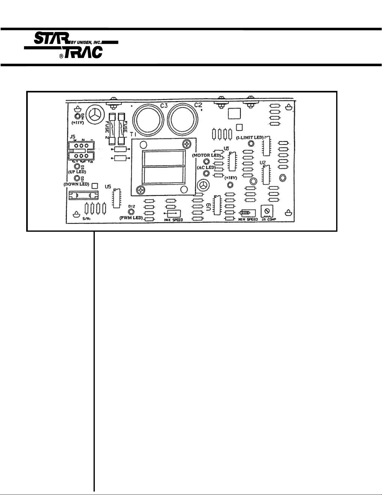
110v MCB LED Layout
The Following LEDs will help diagnose if the MCB has failed or causing intermittent problems.
** CAUTION ** AC LED - Indicates that AC power has been applied to the MCB. It does
Several of the follow- not give indication of voltage level, if this LED is not lit and the tread ing troubleshooting mill does not power up, verify the following:
require dealing with 1. The treadmill is plugged into a wall outlet.
live voltage. Have the 2. The ON/OFF switch is turned to the “ON” position.
treadmill turned off 3. Verify with a VOLT METER that 110VAC is present at the
and unplugged when outlet. Units with step-down transformers need 220VAC.
checking wire 4. Verify 110v (+/- 10%) AC voltage at AC1 & AC2 wires.
connections. After the above have been verified and the AC LED is still “OFF”, the
MCB should be replaced.
NOTE: The display +18v LED - Indicates the presence of an acceptable level of voltage to
console may still operate the MCB. If this LED is off or dim, the AC voltage level is
power up with the AC not acceptable to properly power the MCB. Verify the following:
LED off. 1. Verify with a VOLT METER that 110VAC is present on
on pins AC1 & AC2.
After the above step has been verified and the + 18V LED is still “OFF”,
and the display does not power up, replace the MCB.
+11v LED - Indicates there is +11 volts supplied to the display board. If this
LED is not lit verify the following:
1. The display cable is damaged or pinched, disconnect the
display cable and verify if the LED lights up. If LED lights up
replace the cable.
After the above has been verified and the +11 LED is still “OFF”, the
MCB should be replaced.
4.1

110v MCB LED Layout
NOTE: Engage Motor MOTOR LED - Indicates the presence of acceptable voltage to the motor.
Test Mode and If this LED is not lit one of the following conditions exists:
manually push on 1. Verify AC voltage is being applied.
the running belt to 2. Verify that MTR1/MTR2 wires are connected to the MCB.
verify RPM feedback. (This should be done with the treadmill unplugged and turned off)
After the above have been verified and the MOTOR LED is still ‘OFF”, the
MCB should be replaced.
PWM LED - Indicates that there is a valid control command from the
display to the MCB (this LED flashes only when the treadmill is
operating) If this LED is not lit verify the following:
1. Verify if the display cable is connected.
2. Verify if the display cable is damaged or pinched.
(see page 4.17 in this section for Display Cable
symptoms)
After the above have been verified and the PWM LED is still “OFF” , the
MCB should be replaced.
NOTE: If the current I-LIMIT LED - Indicates that an excessiveload is being placed on the
limit is reached, the motor. Amp readings of 26 or higher will cause the LED to
MCB will shut the light. If this LED is lit one of the following conditions exists:
treadmill down and 1. Running belt is worn.
the I-LIMIT LED will 2. Belt and deck require lubrication.
remain on until it 3. Drive motor drawing over the 26 amp peak.
resets. After the above has been verified and the I-LIMIT LED is still “ON”, the
MCB should be replaced.
UP LED - Indicates that the incline is being commanded up. If this LED is
not lit and the elevation motor will not respond, verify the
following:
1. Display cable for possible pinch or tear (see page 4.17
in this section for Display Cable symptoms)
2. Replace MCB.
DOWN LED - Indicates that the incline is being commanded up. If this LED
is not lit and the elevation motor will not respond, verify the
following:
1. Display cable for possible pinch or tear (see page 4.17
in this section for Display Cable symptoms)
2. Replace MCB.
4.2

220v MCB LED Layout
The Following LEDs will help diagnose if the MCB has failed or causing intermittent problems.
** CAUTION ** AC PWR - Indicates that AC power has been applied to the MCB. It does
Several of the follow- not give indication of voltage level, if this LED is not lit and the
ing troubleshooting treadmill does not power up, verify the following:
steps require dealing 1. The treadmill is plugged into a wall outlet.
with live voltage. 2. The ON/OFF switch is turned to the on position.
Have the treadmill 3. Verify with a VOLT METER that 110VAC is present at the
turned off and unplu- outlet. Units with step-down transformers need 220VAC.
gged when checking 4. Verify 220v (+/- 10%) AC voltage at AC1 & AC2 wires.
wire connections. After the above have been verified and the AC LED is still “OFF”, the
MCB should be replaced, if the treadmill is not operating.
NOTE: The display DISPLAY PWR- Indicates there is +11 volts supplied to the display
console may still board. If this LED is not lit verify the following:
power up with the AC 1. The display cable is damaged or pinched, disconnect the
PWR LED off. display cable and verify if the DISPLAY PWR LED lights
up. If the LED lights up replace the cable.
After the above has been verified and the DISPLAY PWR LED is still
“OFF”, the MCB should be replaced.
4.3

220v MCB LED Layout
NOTE: Engage Motor RPM SENSOR - Indicates input signal from the RPM Sensor to the MCB.
Test Mode and If this LED is not flashing during operation, verify the following
manually push on 1. RPM sensor disconnected from connector J3 at the MCB.
the running belt to 2. RPM sesnor gap misaligned.
verify RPM feedback. 3. RPM sensor faulty
After the above have been verified and the RPM LED is still “OFF”, the
MCB should be replaced.
MOTOR CONTROL - Indicates that there is a valid control command
from the display to the MCB. If this LED is not lit verify the
following:
1. Verify if the display cable is connected.
2. Verify if the display cable is damaged or pinched.
After the above have been verified and the MOTOR CONTROL LED is still
“OFF”, the MCB should be replaced.
UP LED - Indicates that the incline is being commanded up. If this LED is
not lit and the elevation motor will not respond, verify the
following:
1. Display cable for possible pinch or tear ( see page 4.17
in this section for Display Cable symptoms).
2. Replace MCB.
DOWN LED - Indicates that the incline is being commanded down. If this
LED is not lit and the elevation motor will not respond, verify the
following:
1. Display cable for possible pinch or tear ( see page 4.17
in this section for Display Cable symptoms).
2. Replace MCB.
4.4

Calibration
Troubleshooting
The following steps help troubleshoot in case Auto-Calibration procedures fail to give the correct
reading or response.
Symptom:
Auto-Calibration fluctuates.
1. Verify line voltage for sufficient voltage supply.
• If wall voltage is less than 10% than what is
required, this will cause speed fluctuation.
2. Verify unit is on a dedicated circuit breaker.
• Treadmills sharing the same circuit line will cause
intermittent problems and variation in speed.
3. Verify the following parameters are set correctly
in the Configuration Mode:
(Configuration Mode details in Section 3)
• CNT/RV : 31 = Magnetic/Cherry RPM Sensors
• 10 REV: 29.1” for 1.7” dia. motor pulley (110v)
• 10 REV: 35.8 for 2.1” dia. motor pulley (220v)
NOTE: If not sure what your 10 REV settings should
be, manually measure your drive motor pulley
diameter. Above measurements are done in inches.
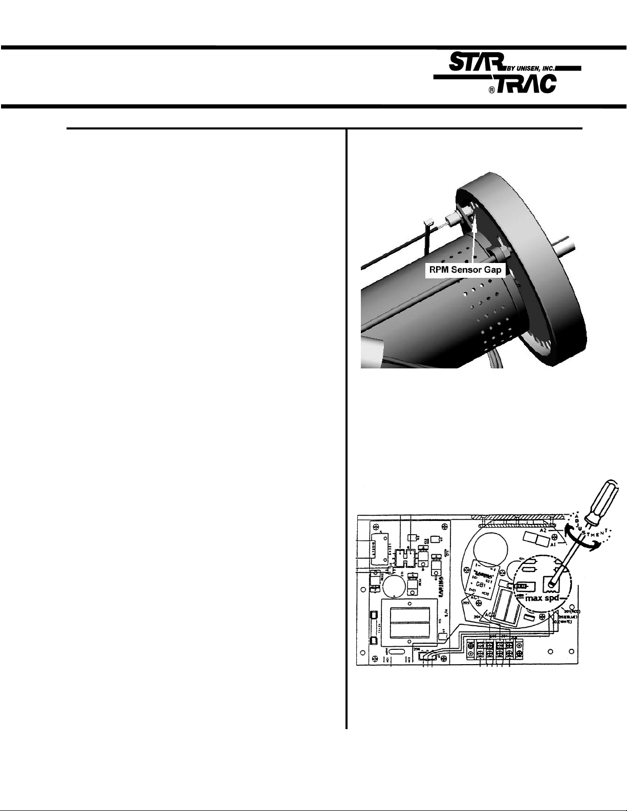
Diagram #1
4. Verify RPM Sensor alignment.
• Hall Effect/Cherry RPM Sensor is being used,
verify the gap is no more than 1/8 inch.
NOTE: See Diagram # 1.
5. Adjust IR COMP potentiometer.
NOTE: See Diagram #2, adjustment.
REPLACE: MCB if symptom continues.
4.5
Calibration Troubleshooting
Symptom:
Will not Calibrate to MAX speed.
1. Verify line voltage for sufficient voltage supply.
• If wall voltage is less than 10% than what is
required, this will cause speed fluctuation.
2. Verify unit is on a dedicated circuit breaker.
• Treadmills sharing the same circuit line will cause
intermittent problems and variation in speed.
3. Verify the following parameters are set correctly
in the Configuration Mode.
(Configuration Mode details in Section 3)
• MN SPD: 0.5 MPH or 1.0 KM/PH
• MX SPD: 10.0 MPH (110v) or 20.0 KM/PH (220v)
• CNT/RV : 31 = Magnetic/Cherry RPM Sensors
• 10 REV: 29.1” for 1.7” dia. motor pulley (110v)
• 10 REV: 35.8” for 2.1” dia. motor pulley (220v)
NOTE: To reach 20.0 KM/PH on 220v units, drive
motor pulley must be 2.1”. If not sure what your 10
REV settings should be, manually measure the drive
motor pulley diameter.
Diagram #1
Diagram #2
4. Verify RPM Sensor alignment.
• Hall Effect/Cherry RPM Sensor is being used,
verify the gap is approximately 3 business
cards or 1 credit card. If adjustment is necessary
loosen the flywheel to re-position.
NOTE: See Diagram #1.
REPLACE: RPM Sensor if RPM reading is sensitive
or feedback appears erratic.
5. Adjust the MAX SPEED potentiometer.
NOTE: See Diagram #2. (220v units only)
GO TO: Section 3.7 Manual Calibration if problem
continues.
4.6

Manual Calibration
The following procedure allows the treadmill to manually calibrate Minimum and
Maximum speeds, only in the case Auto-Calibration is not functioning correctly.
Symptom:
Will not calibrate to MN or MX speed, in the Auto-Calibration Mode.
**CAUTION** 1. Engage TEST MODE. Press and hold the “ 0 ”, “ 1 ” & “ START ” keys together
Do not stand on (or the “0” , “2” ). While holding the “ 0 ” & “ START ” keys down, release the “ 1 ”
the running belt (or 2) key. The display will beep and display SETTINGS (or CONFIGURE)
while perform- momentarily, then UNITS will be displayed.
ing these steps.
2. Press and release the “8” key. Display will read: XXX 3 .0 XXX is a variable
NOTE: Alter- number depending on the elevation position the treadmill is at. 3 indicates Speed
native mode to Command, 0 indicates RPM. If the treadmill is at 0% the display will read: 240 3 .0
enter Motor
Test Mode; turn
the power down the corresponding Speed Command number displayed for each desired
switch “ON” setting.
while pressing
the “8” key sim-
ultaneously on STEP 1.
the display.
NOTE: The MN MN SPD Speed Command number by using the “+” or “-” keys, then press the
SPD should not “START” (enter) key to save the new setting. Do this for the 1/2 MX and MX SPD.
exceed .5 MPH
or 1KPH. The
1/2 MX SPD
should be
exactly half of
the desired MX
SPD. The MX
MX SPD must
not exceed 10
MPH or 20 KPH
(220 units).
3. Press the “+” key (speed) to the desired MN SPD,1/2 MX, and MX SPD. Write
4. Press the “STOP” key. Engage Configuration/Settings Mode as described in
5. Using the “UP ELEVATION” key go to MN PWM parameter and enter the new
6. Press the “STOP” key to exit.
NOTE:Speed
Command
255 is the maximum the tread-
mill will reach.
4.7
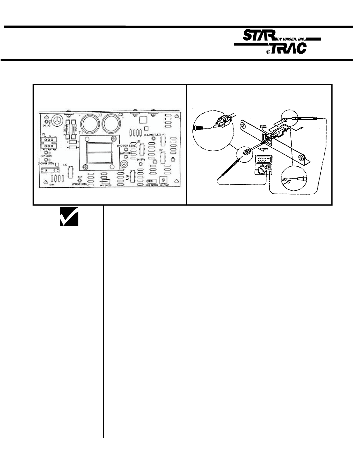
No Display Power
The following steps help troubleshoot in case the display board fails to power up, during or before
regular operation.
110v UNIT
Diagram A Diagram B
1. Lift and suspend the motor shroud.
**CAUTION**
The following steps
are performed with the MCB, does not indicate voltage level. If this LED is lit go to step 3.
the treadmill “ON”. If LED is not lit verify the following: (see diagram A)
less than 90v, check wall voltage, verify unit is on a dedicated line.
REPLACE: MCB if all the above check OK.
2. Verify if LED AC is lit. AC LED indicates that AC power is being applied to
• The treadmill is plugged into the wall.
• The ON/OFF Switch is turned to the “ON” position.
• Verify wire connection AC1/AC2 on the MCB.
• Verify the ON/OFF Switch Breaker wires are connected.
• Verify 110v (+/- 10%) AC voltage at AC1/AC2. if the voltage is 0 or
• If wall voltage is correct, verify linecord continuity. (see diagram B)
3. Verify if LED +18 is lit. LED +18 indicates the presence of an acceptable
level of voltage for MCB operation.
REPLACE: MCB if +18 is not lit.
the display board. If the LED is lit go to step 5.
REPLACE: MCB if +11 is not lit.
4. Verify if LED + 11 is lit. LED +11 indicates 11v are being applied to power
5. Verify display cable connection.
• Verify display cable for possible pinch or tear mark.
REPLACE: Display board if display cable checks OK.
4.8

No Display Power
The following steps help troubleshoot in case the display board fails to power up, during or before
regular operation.
220v UNIT
Diagram A Diagram B
1. Lift and suspend the motor shroud.
**CAUTION**
The following steps
are performed with the MCB, does not indicate voltage level. If this LED is lit go to step 3.
with treadmill “ON”. If LED is not lit verify the following: (see diagram A)
less than 200v, check wall voltage, verify unit is on a dedicated line.
REPLACE: MCB if all the above check OK.
2. Verify if LED AC is lit. AC LED indicates that AC power is being applied to
• The treadmill is plugged into the wall.
• The ON/OFF Switch is turned to the “ON” position.
• Verify wire connection AC1/AC2 on the MCB.
• Verify the ON/OFF Switch Breaker wires are connected.
• Verify 220v (+/- 10%) AC voltage at AC1/AC2. if the voltage is 0 or
• If wall voltage is correct, verify linecord continuity. (see diagram B)
3. Verify if LED DISPLAY POWER is lit. This LED indicates 11v are being
applied to power the display board. If the LED is lit go to step 4.
REPLACE: MCB if DISPLAY POWER LED is not lit.
4. Verify if LED MOTOR CONTROL is lit. This LED indicates there is a valid
control command from the display to the MCB. Verify the following if LED
is off:
• Verify display cable connection.
• Verify display cable for possible pinch or tear mark.
REPLACE: Display board if display cable checks OK.
4.9

Elevation Motor
The following procedure explains the elevation system Thermal Protection and
limitations.
Symptom:
NOTE: Activation
of the thermal
protection breaker does not
cause damage to
the elevation
actuator or other
treadmill components.
Elevation system shuts-off when used consistently.
1. The Star Trac Model 4500 elevation system actuator is protected from
overheating by a thermal protection circuit. In the event that the thermal
protection breaker is activated, the treadmill’s elevation system is temporarily
disabled, and an “EL STL” display codes is displayed.
• A simple resetting of the treadmill restores full operation once the
elevation actuator has been allowed to cool for a few minutes.
2. The pre-defined workout programs 1 through 8 as well as other typical workout
regimens include elevation changes that easily fall within the operating limits of
the Model 4500’s elevation system actuator. The following information serves
as a guide for users that may wish to set a custom program that requires
frequent and/or large changes in incline.
• Incline changes greater than 5 percent should not be programmed for
intervals less than 1 minute.
• Full range incline changes (from 0 percent to 15 percent, or vice-
versa) should not be programmed for intervals less than 3
minutes.
4.10

Elevation Motor
The following procedure verifies elevation motor potentiometer response.
** CAUTION **
Do not stand on
the running belt
while performing
these steps.
NOTE: Several of
the following
steps require
dealing with “live”
voltage. Have the
treadmill turned
off and unplugged when checking wire connections.
NOTE: The potentiometer values
can be read in
Motor Test Mode,
240 = 0%, 57 =
15% for 110v
units or 80= 15%
for 220v units.
NOTE: The
values in diagram A were taken
from a properly
functioning
elevation system.
You may expect
slight variation
from machine to
machine. If the
values are 0,
check display
cable for possible
short see page
4.17 Display
Cable Symptoms.
If values are erraticly different
replace the
Elevation Motor.
Symptoms:
Elevation motor hesitates during operation.
No elevation count reading in Test Mode.
1. The elevation motor potentiometer may have failed or register incorrect values
causing the motor to hesitate while operating. The chart below (see diagram A)
is a guide for the correct elevation readings on the TR 4500.
• Using a Volt Meter verify the following values from the elevation motor at
certain elevation grades (see the chart for elevation grades).
The voltage readings may vary by +/- .05 volts. The ohms may vary by
+/- .01 k ohms. See diagram B for meter reference.
Diagram A.
% Grade Incline
number in
Motor Test
Mode
0 240 4.68 9.76k 4.8
1 228 4.44 9.33 k 4.58
2 216 4.21 8.86 k 4.37
3 204 3.98 8.41 k 4.12
4 192 3.75 7.92 k 3.88
5 180 3.51 7.48 k 3.64
6 168 3.27 6.95 k 3.42
7 156 3.04 6.48 k 3.18
8 144 2.81 6.01 k 2.95
9 132 2.57 5.50 k 2.71
10 120 2.34 4.98 k 2.48
11 108 2.11 4.48 k 2.26
12 96 1.88 3.99 k 2.03
13 84 1.64 3.52 k 1.79
14 72 1.41 2.97 k 1.55
15 60 1.17 2.48 k 1.33
DC Voltage across
Blue and Orange
wire on the Elev.
motor connector
Ohm reading between
the Blue and Orange
(elev. motor
unplugged)
DC Voltage on
Pin 4 of the
electronics
display
4.11

Elevation Troubleshooting
220v treadmill Incline Range Adjustment for Free-wheeling symptom.
** CAUTION **
Do not stand on
the running belt
while performing these steps.
Symptom:
Treadmill free-wheels at high elevation, causing the running
belt to slowly accelerates beyond the selected speed.
1. This symptom may be easily fixed by changing certain values in the Configure
Mode. Engage Manager/Maintenance Mode by holding down the “0”, “1” and
“Start” keys at the same time, and then release the “1” key only.
2. Press the elevation “↑” key until the display window reads “EL MAX 57”.
Change the “57” to “80” by pressing the “+” key.
3. Press the “START” key and the display window will show “UPDATING”. This
will save the “80” in the parameter.
4. Press the “STOP” key to exit the Manager or Maintenance Mode. Procedure
completed.
Symptom:
Elevation Motor overheats and blows the MCB fuse.
NOTE:These ranges were chosen
to optimize the
output voltage to
the elevation
motor within an
acceptable
operating range,
while still using
the present
manufacturing
tolerances of the
transformer
manufacturer.
1. The elevation motor on the 4500 series treadmill uses 115 VAC. On 230 volt
treadmills, there is an autotransformer which will lower the voltage to operate
the elevation system.
2. Line voltage may vary from location to location. Some locations have line
voltages as low as 195 VAC or as high as 250 VAC. The autotransformer has
been manufactured with two taps to accommodate these variations in voltage.
The two taps are:
• 190 to 210 VAC line voltage
• 210 to 250 VAC line voltage
4.12

Speed Troubleshooting
Symptom:
Note: This sym-
ptom may be
easily fixed by
verifying certain
values in the
Configure Mode.
Note: For each
value changed
the “ENTER” key
must be pressed
to be saved.
.
Treadmill appears/feels faster/slower than other STAR TRAC
treadmills.
1. Engage Maintenance Mode by holding down the “0”, “2” and “Start” keys at the
same time, and then release the “1” key only. Display will read MAINTENANCE
momentarily then display UNITS.
2. Using the elevation “ ↑ “ key to go through the parameteres, verify the
following parameterts have the correct values.
110V / 220V Units English 220v Units Metric
• UNITS ENGLISH METRIC
• MN SPD 0.5 1.0
• MX SPD 10.0 20.0
• ENTRY UNITS/TENTHS UNITS/TENTHS
• 10 REV 30.7 35.8
• CNT/REV 31 31
3. If any values have been changed or set back to default settings, re-engage
Auto-Calibration and re-calibrate.
4.13

Speed Troubleshooting
Symptom:
Note: This sym-
ptom may be
easily fixed by
verifying certain
values in the
Configure Mode.
Treadmill will not reach maximum speed.
1. Engage Maintenance Mode by holding down the “0”, “2” and “Start” keys at the
same time, and then release the “1” key only. Display will read MAINTENANCE
momentarily then display UNITS.
Note: For each
value changed
the “ENTER” key
must be pressed
to be saved.
Note: All 110v
units are designed to reach a
maximum speed
of 10.0 MPH.
220v units set in
metric will reach
a maximum 20.0
KM/PH.
Note: Wall voltage is very critical
when dealing
with maximum
speed. Voltages
under 100v for
110v units will
cause speed
variation, voltages under 200v
for 220v units will
cause the same
problem.
2. Using the elevation “ ↑ “ key to go through the parameters, verify the
following parameters have the correct values.
110V / 220V Units English 220v Units Metric
• UNITS ENGLISH METRIC
• MN SPD 0.5 1.0
• MX SPD 10.0 20.0
• ENTRY UNITS/TENTHS UNITS/TENTHS
• 10 REV 30.7 35.8
• CNT/REV 31 31
3. If any values have been changed or set back to default settings, re-engage
Auto-Calibration and re-calibrate.
IF the problem continues verify the following.
1. Wall voltage. (+/- 10%)
2. Dedicated Circuit Breaker.
3. Adjust MAX SPEED potentiometer (220v units). See Diagram below:
Note: Each unit
must be on its
own dedicated
circuit, very main
wall breaker.
4.14

Speed Troubleshooting
Symptom:
** CAUTION **
Running belt will
be moving at high
speed during
Step 1 & 3.
** CAUTION **
When checking
motor brushes
have the treadmill
turned off and
unplugged.
Note: Brushes
should show a
smooth pattern of
wear, cracks or
unusual wear will
cause motor to
jerk, replace if
brushes if neded.
Treadmill jerks or hesitates during operation.
1. Verify the running belt / drive belt are not loose or slipping.
• Accelerate the running belt to 3.0 (5.0 kph). Stand on the side of the
treadmill, while grasping the handrails firmly, place one foot on the
running belt with a very sharp impact. Running belt should not stop,
instead slip for a split second forcing your foot back. Drive belt should
never stop rotating over the headroller during this procedure.
• If running belt or drive belt appears loose, see page 4.26 in this section.
2. Verify motor brushes are making contact and are seated correctly.
• Remove the motor brush cover, check brushes are seated correctly by
removing the brush clip and verify contact. See diagram A for removal
instructions.
• Cleaning the motor armature with a commutator stone is highly recom-
mended to remove any possible carbon dust build up, causing the
the brushes to skip over resulting in a brief motor hesitation.
3. Adjust the IRCOMP potentiometer, located on the MCB, see diagram B.
• Bring the treadmill to its minimum speed.
• Stand on the running belt, if the belt feels jerky / hesitates adjust the
IRCOMP potentiometer until running belts feels smooth.
Symptom:
Treadmill hesitates during initial speed start-up.
1. Manually calibrate the minimum PWM as described in page 4.7 in this
section.
4.15

Heart Rate Troubleshooting
Before any troubleshooting is performed, verify that the heart rate grips are being used
** CAUTION **
Do not stand on
the running belt
while performing
these steps.
and maintained properly.
Symptom:
Intermittent or erratic heart rate reading.
1. User failing to grip all four rings completely with both left and right hands
2. An excessively tight grip on the rings can cause erratic readings. The
probability of erratic readings can be therefore lessened by:
---- reduced upper torso movement
---- a proper grasp on the grips
---- clean hands
---- clean grips
3. Excessive foreign matter (dirt) on the hands can generate electrical
interference which will cause erratic readings.
4. Clean and wipe heart rate grips after each use, for optimum results.
4.16

Heart Rate Troubleshooting
Symptom:
No Heart Rate reading.
1. Engage HEART RATE TEST. Turn the
power switch “on” while pressing key “5”
simultaneously on the display. All the
display LEDs will light up when engaged.
• Press the HEART key once, EPROM ver sion will be displayed. HEART key twice,
displays Heart/ Seeking HR.
• Grip heart rate handles, The negative (-)
symbol will begin to flash indicating heart
rate system is being registered. Do not
squeeze excessively to avoid excessive
muscle contraction (faulse readings). If
no reading is displayed go to STEP 2.
Engage MANAGER MODE, Hold the “0”,
“1”, and “START” keys together and re lease the “1” key only. Display will read
MANAGER MODE momentarily, then
UNITS will be displayed.
elevation “UP” key until display reads:
CONTCT= contact heart rate.
BOTH = both contact and polar can be
used (if software available).
“START” key to save.
2. Verify Contact Heart Rate settings.
• Scroll through the parameters using the
• Press the “+” or “-” key to change,
Diagram 1
Diagram 2
3. Verify Heart Rate receiver connection.
• Remove the display board, verify wire
connections.
NOTE: See diagram #1 Display removal.
NOTE: See diagram #2 Wire connection.
Connection is wrong or loose, reconnect
and repeat step 1.
4. Verify Heart Rate grip cables.
NOTE: See diagram #3. If connections are
wrong or loose, reconnect and repeat step 1.
4.17
Diagram 3

Heart Rate Troubleshooting
5. Connect Heart Rate Board straight to
the display input.
• By-pass the Combiner Board, insert the heart
rate wires straight to the display.
See Diagram #3 & 3a. After connection has been
repeat step 1.
REPLACE: Combiner Board if Heart Rate
registers. If no Heart Rate is registered go to
step 6.
NOTE: Step 5 can only be performed if the
software includes both Polar and Contact.
6. Check continuity/resistance between
Heart Rate grip rings and input wires.
• Disconnect both heart rate grip inputs (red &
black wires) from back of display.
• Using a Multi-meter check continuity between
the heart rate rings and its corr-
esponding output wires.
• Red wire = outside rings.
• Black wires = inside rings.
NOTE: See Diagram #4.
REPLACE: Heart Rate grip(s) if reading is
greater than 1.0Ω
Diagram 4
Diagram 5
Diagram 6
7. Check continuity/resistance of each
hand rate grip.
• Using a Multi-meter check continuity between
the two rings on the same grip.
• Black meter probe to inside ring and red
meter probe to outside ring.
NOTE: See diagram #5.
REPLACE: Heart Rate grip(s) if reading is lower
than 3 MΩ.
8. Check continuity/resistance between
the two hand rate grips.
• Measure the resistance between the two
outside rings.
NOTE: See diagram #6.
REPLACE: Heart Rate grip(s) if reading is
less than 18.0Ω
Diagram 7
4.18

Polar Heart Troubleshooting
If the display is having difficulty picking up polar heart rate readings, verify proper
usage.
** CAUTION **
Do not stand on
the running belt
while performing these step.
NOTE: Secure
the chest strap
transmitter as
high under the
pectoral muscle
(breast) as is
comfortable and
allow normal
breathing.
NOTE: Wet the
electrodes (the
two grooved
rectangular
areas) thoroughly with water.
Symptom:
Intermittent or erratic polar heart reading.
1. The maximum distance for polar heart rate to receive a signal is 3 feet.
2. Verify chest strap is correctly positioned. Chest strap electrodes must be
properly positioned and wet. See below diagrams.
NOTE: Verify
heart rate response without
operating the
running belt.
Straddling the
treadmill press
the HEART key
If heart rate is
not picked up
engage Heart
Rate Test, refer
section 2.8
3. Connect Polar Board straight to the display input.
• By-pass the Combiner Board, insert the heart rate wires straight to the
display. See Diagram 1 # 1a
REPLACE: Polar Board if Heart Rate registers. If no Heart Rate is registered go to .
4.19

Display Cable
The following symptoms indicates a faulty or pinched display cable.
Symptom:
No display power related.
**CAUTION** 1. No display power, treadmill elevation bottoms out during start-up.
Do not stand on 2. No display power, MCB LED +11 remains lit on 110v units. MCB LED Display
the running belt remains lit on 220v units.
while perform-
ing these steps.
1. In Test Mode only up direction works, MCB LED “UP” remains lit.
NOTE: Alter- 2. In Test Mode no elevation count (elevation motor pot), will elevate both directions
native mode to reads EL LOST across display in regular operation mode.
enter Motor 3. In Test Mode no elevation response, reads EL STL across display in regular
Test Mode; turn operation mode.
the power 4. In Test Mode elevation count registers slow to actual elevation response.
switch “ON” 5. Treadmill elevation without command in regular operation mode.
while pressing 6. Elevation motor hesitates in between elevation percents, MCB LEDs “UP” &
the “8” key sim- “Down” toggle back and forth.
ultaneously on 7. Elevation intermittently responds, registers different elevation display codes in
the display. regular operation mode.
Intermittent or no elevation.
Intermittent or no speed reading
1. In Test Mode belt movement, but no RPM reading. MCB LED RPM remains of
on 220v units. registers NO RPM code across display in regular operation mode.
2. In Test Mode or regular operation mode, RPM reading intermittently flashes.
3. In Test Mode or regular operation mode, RPM speed fluctuates.
4. In Test Mode MCB LED PWM (110v units) or MOTOR CONTROL (220v units)
remains off and no RPM reading is registered.
4.20

Drive Motor
The following symptoms indicates a faulty drive motor.
Symptom:
Tripping the ON/OFF switch breaker.
**CAUTION** 1. Disconnect the drive motor belt.
Do not stand on
the running belt ON/OFF switch trips, verify if the MCB LED I-LIMIT lights up (110v units), this
while perform- would indicate Drive Motor pulling higher amps than desired.
ing these steps.
NOTE: If the
ON/OFF swith 1. Disconnect the drive motor belt.
trips only with a 2. Isolate the noise. Bellow is a list of discriptions related to motor noise:
load, running ----Knocking; Noise described for bearing failure or motor magnet.
belt may be ----Grinding ; Noise describing bearings, motor brush wear.
worned. ----Squeaking; Motor brushes installed incorrectly, flywheel loose, motor
bearings.
----Howling; Usually described when motor increases to higher speeds.
2. Run the drive motor for ten minutes at a high speed (6 MPH/ 10 KPH). If the
Drive Motor making noise.
4.21

Head / Tail Roller
You may need to replace the head or tail roller if the following symptoms are
observed.
Symptom:
Thumping, knocking noise as the running belt goes over the
roller.
Verify the following:
• Delron end caps are loosening.
• Bearings are grinding or knocking.
• Lagging (coating) is loose.
• Thumping sounds (may also indicate a possible wax build up).
Note: Do not
remove all the was
as it is required to
lubricate both the
running belt and
deck.
The running deck surface is coated with a special wax. During breaking
period (first 20 – 30 hours of operation), some wax may form on the tail
roller causing a loud thumping noise. In worse cases, this may cause mistracking. If the thumping noise continues, remove the wax buildup. With the
following procedure:
1. Loosen or remove the tail roller by backing of the Allen screws. Use a ¼
“ Allen wrench.
2. Remove the largest buildup of wax deposits from the tail roller. Use a
plastic scraper, credit card or piece of wood. Never scrap with a sharp
metal object.
4.22

Drive Belt Troubleshooting
The drive belt tension may require tightening if a slipping problem occurs on the drive
pulley.
Symptom:
Running belt slips when running or walking.
1. Loosen the four motor mount kep nuts and washer using a 5/16 “ wrench.
2. Adjust the drive belt tension by turning the motor mount adjustment
(socket head cap) screw. See diagram below. Tension should be no more
than 90 lbs.
• If too tight, turn the belt tension screw counter-clockwise.
• If too loose, turn the belt tension screw clockwise.
3. Simultaneously tighten the belt tension lock nut while holding the belt
tension screw with a 5/16” wrench.
4. Simultaneously tighten the right, rear, motor mount nut, then tighten the
remaining bolts.
5. Verify if the belt is tensioned properly.
4.23

Running Belt Troubleshooting
Note: For optimal To prevent belt problems from occurring, verify the running belt is properly
performance during the adjusted and working smoothly by performing the following steps:
lifetime of the treadmill,
running belt adjust-
ments may become described as a smooth glass texture, the correct feeling should be a
necessary. All adjust- rough texture such as found on the undersides of the belt.
ments are performed
by adjusting the tail
roller Allen screws If glazed, replace the running belt. Contact your local retailer or act
with a 1/4” Allen STAR TRAC Product Support Department at 800-501-1221 or through
wrench. our web site at http://www.startrac.com.
inspect the running belt. The running belt should move smoothly, without
drifting to far to the left or right. This will cause fraying or damage to the
running belt. For proper tension and tracking, refer to Running Belt
Tension and Running Belt Tracking in this section.
If you observe the following symptoms, running belt needs to be replaced
1. On/off switch tripping to the “off” position after treadmill is used for short
period of time.
2. Running belt continues to slip after tightening . (Provided the drive belt has
been checked for proper tension)
1. Feel the underside center of the running belt, for glaze. Glaze is
2. Activate the treadmill. Stand at the back of the treadmill and visually
3. Edges of the running belt are frayed.
4. Running belt seam is coming apart.
5. Running belt beginning to fold in the middle.
4.24

Running Belt Tracking
Note: The running belt If the running belt is not centered on the tailroller and is either to far left or
may mis-track due to right, adjust tracking using the following steps::
the style of the walker
or runner.
Note: The running belt
will track to the side sides of the tail roller with a 1/4” Allen wrench in 1/4 turn increments.
less tensioned. (See below diagram)
If the running belt is tracking to the left, adjust the running belt to track
to the right. Tighten the left tailroller Allen screw by turning clockwise
or loosen the right tail roller bolt by turning counter-clockwise.
If your running belt is tracking to the right, then adjust the running belt to
track to the left. Tighten the right tail roller Allen screw by turning clock wise or loosen the left tail roller bolt by turning counter-clockwise.
mph (16 kph) and verify belt stays centered.
Tension procedure in this section.
4. Verify correct running belt tension as outlined in the Running Belt
1. Turn treadmill on. Increase speed to 3.0 mph (5.0 kph).
2. Adjust tracking by adjusting the tailroller Allen screws located at the back
3. After running belt appears to be tracking properly, increase speed to 10
Note:To ensure proper
tracking, the treadmill
leveling feet must be
adjusted to conform
to the floor surface.
For proper procedure
see Feet Leveling in
this section.
4.25

Running Belt Tension
Note: Prior to making The running belt tension may need to be adjusted over time to keep the
any adjustments to the the belt from slipping with each jogging step or at high speeds. Use the
running belt tension, following procedure for testing belt tension.
verify the drive motor
belt is properly
tensioned.
foot on the running belt with a very sharp impact. The running belt should
not come to a complete stop. The running belt should slip for a split
second, then forcing your foot back.
If the running belt does not stop with impact, the running belt may be to
tight and cause the belt and other components to premature fail.
Loosening the tail roller Allen screws a 1/4 of a turn counter-clockwise and
re-checking will be necessary.
If the running belt stops and noticeable slippage occurs, check the
location of the slippage. It can be slipping due to the drive belt slipping
over the drive motor pulley and head roller or from the running belt
slipping over the rollers.
---- If the slippage is caused from the drive belt slipping over the drive
motor pulley, loosen the motor mount bolts located at the mount
of the drive motor and tighten the adjustment bolt. For detail
more details refer to Drive Belt Tension procedure in this
section.
--- If the slippage is caused by the running belt slipping over the
rollers, tighten the running belt.
1. Accelerate the running belt to 3.0 mph (5.0 kph).
2. Stand on the side of the treadmill. Grasping the handrails firmly, place one
Note: If you do not
tighten Allen screws in increments. Repeat Step Two until running belt is tensioned properly.
equal increments, you
will mis-track the
running belt. Verify
correct belt tracking
procedure.
The running belt has been tightened too much and may require loosening, if:
Note: Do not over 1. The edges of the running belt curls down or up, causing the middle of the
tighten the running belt. belt to bubble up.
Over tightening will
cause premature 2. Running belt creaks as it goes over the rollers.
failure.
Note: If the running 3. Treadmill trips the circuit breaker (on/off switch) after tensioning.
belt creaks in spite of
being loosened, apply
dry lubricant, such as
TFE Teflon or powered
wax to the deck.
3. Tighten the left and right tail roller Allen screws clockwise in equal 1/4
4.26

Running Deck
The following procedure will help determine and properly adjust the deck bumpers.
Symptom:
Running deck squeaks when running.
1. When properly located, the side bumpers (two on each side) bear against the
delrin rods in the frame rails. The rear bumpers bear against the steel posts at
the end of the frame rails. If the bumpers are not located so they bear against
the rods as described, the running deck may shift to one side or the other
during use. This allows the rear edge of the deck to rub against the steel post.
This causes a high-pitched squeak as the user runs on the treadmill.
2. To determine if a deck has the bumpers properly located, look under the end
cap/finger guard to see if the bumpers on the end of the deck bear against the
steel posts. A problem definitely exists if the bumpers are to one sode of the
steel posts and the edge of the deck is bearing against the posts.
3. Remove the screws securing each of the four delrin rods and pull them out.
Look through the hole in the frame to see if the running deck bumper is
adjacent to the hold, such that it would bear against the delrin rod if it was
reinstalled in the hole. If all bumpers are properly located, replace the delrin
rods and examine the treadmill further for the other causes of squeaks. If one
or more bumpers is misalign, follow the procedure given below.
4.27

Running Deck
Symptom:
Running deck squeaks when running (continued).
Correcting the problem:
1. Position the deck with the rear bumpers properly aligned with the steel posts.
With a pencil, make a mark on the deck adjacent to each of the four delrin rods(
as seen from the top of the side rails).
2. Reach under the running deck, shift the deck as far as possible to tone side. On
the side that now has the edge of the deck exposed from under the frame, pull
the rear edge of the deck upward until it is just above the frame rail. Use a
screwdriver or putty knife to hold the deck above the frame. Using another
screwdriver, raise and hold the front of the deck.
3. Remove the bumper(s) that are not aligned with the pencil marks by carefully
prying them away from the deck with a screwdriver, knife or putty knife.
4. Position the bumpers (removed in the previous step) so they are adjacent to the
pencil mark(s), and drive them into the edge of the deck using a hammer.
5. Once the bumpers on the side have been installed in the proper locations,
remove the screwdrivers used to hold the deck above the frame.
6. Repeat process on opposite side of the treadmill.
7. After the bumpers have been properly installed on both sides of the running
deck, position the deck properly, and verify that all bumpers have adjacent o
the holes. Reinstall the delrin rods.
8. Test the treadmill thoroughly. The squeak should be gone.
4.28

NOTE: Verify that
the treadmill is level
before isolating any
specific component
Isolating Noise
Sounds travel throughout the treadmill making it difficult to isolate the cause of a
sound. The following procedure will help determine where a noise may be coming
from.
Isolate the noise.
1. If the noise seems to be coming from two different parts (drive motor or roller
etc.), isolate the noise by disconnecting the drive belt. Then run the drive motor
by itself. If the noise goes away, manually push the running belt to see if the
noise returns. If it does, then it is coming from the rollers.
2. Isolate the rollers. Adjust the tension on the tail roller screws until the running
belt is loose. Spin each roller by itself to determine where the noise is coming
from.
NOTE: Ensure all
assembly screws
are tight:
1. Handrails.
2. Display board.
3. Motor shroud.
NOTE: When doing
the stethoscope
method, be careful
of body placement.
Ensure all loose
items (hair, clothing
, jewelry etc) are
secure and away
from moving parts.
The Stethoscope Method
Using a long screwdriver as a stethoscope put the handle of the screwdriver to
1.
your ear. Place the opposite end of to the area where you are listening. This will
help locate where a specific noise is coming from.
Symptoms:
Rumbling
Wax buildup on the rollers.
•
• Head / tail roller bearings.
• Adjustable feet / leveling.
• Floor condition; thick carpet or wood floors.
Elevation screws dry.
•
• Elevation motor stripped.
Squeaking
Deck rubbing against the frame.
•
• Adjustable feet / leveling.
• Head roller and drive motor pulleys not aligned.
• Drive belt tensioning.
• Running belt tensioning.
• Drive motor brushes.
Knocking
Drive motor bearings.
•
• Head / tail roller bearings.
• Running belt hitting the back or front of the frame.
• Missing or worn deck cushions.
Grinding
Drive motor bearings.
•
• Head / tail roller bearings.
Motor brushes worn. 4.29

Leveling
To ensure proper tracking of the running belt, treadmill leveling should be verified.
Symptoms:
NOTE: If a leveling
foot does not make
contact with the floor
or if it lifts upwards
as weight is applied
to one corner of the
deck, this will cause
the running belt to
mis-track.
• Running belt travels to one side.
• Treadmill vibrates.
Leveling feet must be adjusted to conform to the floor surface. After the treadmill
has been leveled, tracking of the belt must be tested and adjustments made as
necessary. This two step procedure is particularly important for treadmill installed in
a residence, where floors are commonly uneven. When a treadmill is installed on
carpet, a repeat adjustment may be required after the carpet and padding have
been compressed by the treadmill feet.
1. Place the treadmill in the exact location where it is to be used.
2. Check the leveling feet at each corner of the treadmill to ensure that they make
contact with the floor surface. It may be helpful to have one person bear their
weight at one corner of the running belt, then move to another corner, etc.,
while another person notes whether one or more corners lift from the floor as
weight is applied.
---- Using a 9/16 inch open end wrench, loosen the lock number (see diagram).
---- Adjust leveler height by turning the leveler base. The wrench may be used on
the lower nut for this purpose.
---- Tighten the lock nut.
4.30

NOTE: For complete
leveling procedure, see
the following page.
Vibration
A treadmill vibrates during use if the floor or leveling feet are uneven or when
assembly bolts are loose.
Symptom:
Unit vibrates while running.
1. Verify the treadmill is on an even, uncarpeted floor.
• If no, move the treadmill to an even floor.
• If floor is carpeted, place the treadmill on a rubber mat.
2. Verify that the Leveling feet are adjusted correctly.
3. Verify the following assemblies.
• Handrails
• Slick deck
• Display board
• Motor mount
• Flywheel
NOTE: When checking
motor brushes, the
treadmill must be
turned off and
unplugged.
4. Remove the drive belt and isolate the motor.
• If the drive motor vibrates, check motor mount bolts.
• Verify that the motor brushes aren’t cracked.
4.31

**CAUTION**
When checking motor
brushes, always turn
the treadmill off and
unplug.
Static Shock
The treadmill may cause a slight shock from the display panel or handrails, due to
a faulty ground wire or a worn running belt and deck.
Symptom:
Slight shock from handrails or when using the display panel.
1. Check the line cord and plug prongs for signs of damage.
• Verify no prongs are broken, loose or missing.
2. Check the green ground wires attached to the frame for the following:
• Motor
• Line cord
3. Check running belt condition.
• Check for glazing. Replace the running belt if glazed.
• Wax slick deck.
4. Check drive motor conditions
• Verify motor brush wear.
4.32

Display Codes Chart
STAR TRAC recommends that you refer your questions about your STAR TRAC
4000 TREADMILL operation and suspected malfunctions to STAR TRAC’s PRODUCT
SUPPORT DEPARTMENT. However, you may wish to investigate display codes that appear on
** CAUTION **
Do not stand on
the running belt,
while performing
these steps.
NOTE: Treadmill
should be turned
off and unplugged from the
wall when looking
under the motor
shroud.
NOTE: Contact
STAR TRAC
Product Support
Department at
1-800-501-1221
or through our
web site at http://
www.startrac.com
Please have your
serial number
and display code
available.
the display. You may do so by reviewing the below chart or follow the step-by-step flowcharts
for the corresponding display code.
Display Codes/Symptoms
KEY DN
• This code generally occurs when a key other than “5” or ”8” is held pressed while turning
the treadmill ON using the on/off switch.
• It may also happen if a key becomes stuck.
NO STO
• This code generally occurs when the Stop Switch is not connected tightly to the electronic
board of the Display.
• It may also happen if the circuitry associated with the switch develops a fault.
NO RPM / SP CNG
• These codes generally occur when the RPM (speed sensor) is disconnected, faulty, or
misaligned.
• They may also happen if the RPM Sensor cable is damaged.
• Motor Control Board (MCB) is misadjusted, miscalibrated. or faulty.
• Pinched or faulty Display Cable.
• Drive Motor arcing or faulty.
EL STL, EL RNG, EL LOST and EL NOZ
• These display codes generally occur when the elevation (incline) potentiometer is faulty or
out of limits.
• Elevation motor disconnected or receiving low power.
• May also happen if the MCB is miscalibrated or faulty.
• Display Cable pinched or faulty.
• Elevation Belt damaged or binding.
4.33

Definition:
Code: KEY DN Flowchart
Possible Cause:
shorted key/keypad.
Note 1:
This code
may occur when a
user tried entering
"Test Mode"
or "Display Test
Mode" using the
wrong key.
Look for any
indentations on any of
the keys. The plus or
fast key are used
most often and may
cause this error.
Note 2:
Press and hold
the "0", "2" & "START"
keys down at the same
time, then release the "2"
key. The display will
read: MAINTENANCE.
Press and release the 5
manually hold the 5 key
and simultaneously turn
the treadmill on by the on
key.
Or
& off switch.
"KEY STUCK"
Damaged or
Start
Reset the treadmill.
Turn unit off, wait 2
seconds then retry.
See (note 1)
Code
continues to
display
?
YES
Engage
"ENGINEERING"
mode. Verify keypad
response in "Display
Test". See (note 2)
NO
Stop
Note4 :
Carefully peal
off the affected
keypad. Wipe the
display surface with
degreaser (Windex
works well). Re-apply
the keypad starting
from one edge and
using your fingers or
a rag press the
keypad in one
direction to remove
the air bubbles.
Press each key. Verify
that the display beeps
and changes LED
segments with every
key on the display.
keys respond
YES
All
NO
?
Replace display
panel.
YES
Note 3:
If you are
unable to enter the
"ENGINEERING" or
"Display Test",
the panel may have a
key that is permanently
stuck. Replace the
display panel. If any of
the LED segments do not
light up, there may be a
failure in the electronics
and you will need to
replace the electronic
board only.
Note 4:
while the treadmill is on.
The PWM LED indicates
a valid control command
PWM Board. If the LED is
connection and look for
Verify that the
PWM LED is flashing,
is being sent from the
Display Board to the
not flashing, check
pinch or tear marks.
Does
display engage
Display mode
?
NO
Replace display
faceplate.
See (note 3)
Stop
4.34
Stop
Stop


Definition:
Code: NO RPM Flowchart
Possible Cause:
misaligned RPM sensor.
Note 1
: Press and hold
the "0", "1," & "START"
keys down at the same
time, then release the "1"
key. The display will
read: MAINTENANCE.
Then press and release
the 8 key.
Or manually hold the 8
key and simultaneously
turn the treadmill on by
the on & off switch.
Both methods will
engage "Test mode".
Note 2:
Verify that the
PWM LED is flashing,
while the treadmill is on.
The PWM LED indicates
a valid control command
is being sent from the
Display Board to the
M.C.B. If the LED is not
flashing, check
connection and look for
pinch or tear marks on
the display cable.
Note 3:
Verify that RPM
feedback is being
displayed under speed
as the running belt
moves.
Note 4:
To engage
automatic speed
calibration, press the
"HEART" key. Display
will read: CALI. Treadmill
will then go into a self
auto speed calibration.
This will automatically
calibrate MIN PWM, 1/2
max, and MAX PWM for
min and max speed. This
will take less than 3
minutes. Treadmill will be
in motion, during this
test.
"RPM LOSS"
Damaged or
Start
Engage
"MAINTENANCE"
mode. Verify RPM
feedback in "Test Mode".
See (note 1)
Display reads:
XXX 3 .0
(at 0%, XXX will read 240)
Press the "+" and bring
the middle number 3 up to
50.
Does
the running
belt move
?
NO
Left motor shroud and
verify PWM LED for
110v units or MOTOR
CONTROL LED for 220v
units
response. See (note 2)
& Diagram #1
PWM
LED responds
?
YESNO
display read
RPM feedback
YES
see (note 3)
Bring the speed back to
.0 then engage
automatic speed
calibration.
See (note 4)
unit auto
calibrate
1B1A
Does
?
YES
Does
?
YES
Stop
NO
Check the following:
1. RPM connection to
J3 connector.
2. Check alignement.
See (note 5)
Diagram #2 & 3
NO
2A
4.36

Code: NO RPM Flowchart
Note 5:
RPM
Sensor gap
between the Halll
Effect pickup adn
teh flywheel should
be no more than 1/8
inch. If not, adjust
the RPM sensor to
correct gap.
1A
If no appearant damage
is visable. Manually
toggle the display cable
for possible intermittent
connection.
If the PWM LED does
not flash or
intermittently respond,
replace the display
cable.
STOP
2A
Process
Diagram #2
Does
display read
RPM feedback
?
YES
Engage automatic
speed calibration.
See (note 4)
Stop
NO
Replace RMP
Sensor
Stop
4.37

Code: NO RPM Flowchart
1B
Check the following
connections; drive
motor to choke/filter
to MCB.
Re-engage Test Mode.
Bring speed command
3 back up to 50.
Does
the running
belt move
?
NO
By-pass the choke/filter
from the MCB and drive
motor.
Does
the running
belt move
?
NO
YES
Re-engage Auto-
Calibration.
See (note 4)
Stop
YES
Replace the choke/filter
system.
Replace the MCB
Stop
4.38
Stop

Definition:
Code: SP CNG Flowchart
"SUDDEN SPEED
CHANGE."
Possible Cause:
misaligned.
Note 1:
Press and hold
the "0", "1", & "START"
keys down at the same
time, then release the "1"
key. The display will
read: MAINTENANC,
press and release the
Or, manually hold the
simultaneously turn the
treadmill on by the on &
Note 2:
while the treadmill is on.
The PWM LED indicates
a valid control command
is being sent from the
M.C.B. If the LED is not
connection and look for
potentiometer clockwise
or counterclockwise.
Note 4:
displayed under speed
then
"8" key.
"8" key and
off switch.
Both methods will
engage
"Test Mode".
Verify that the
PWM LED is flashing,
Display Board to the
flashing, check
pinch or tear marks.
Note 3
: Adjust the
Verify that RPM
feedback is being
as the running belt
moves.
RPM pick-up
Start
Engage
"MAINTENANCE"
mode. Verify RPM feedback
in "Test Mode". See (note
1)
Display reads:
XXX 3 .0
( at 0%, XXX will read 240)
Press the "+" and bring
the middle number 3 up to
50.
Does
the running
belt move
?
NO
Left motor shroud and
verify PWM LED for
110v units or MOTOR
CONTROL LED for
220v units response.
See (note 2)
Diagram #1
YES
Does
drive motor
surge
?
YES
Adjust the IRCOMP.
See (note 3)
Diagram #2
Does
drive motor
surge
?
YES
NO
NO
Diagram #1
Does
display read
RPM feedback
see (note 4)
?
YES
1C
NO
1D
1B1A
4.39

Code: SP CNG Flowchart
Note 5:
one brush at a time.
Check for unusual
Turn the
treadmill off and
unplug. Remove
wear, replace if
needed.
1A
LED responds
?
NO
Manually toggle the
display cable for
possible intermittent
connection.
If the PWM LED does
not flash or
intermittently respond
when cable is toggled,
replace the display
cable.
YES
Replace the M.C.B.
Stop
1B
Check motor brushes,
for unusual wear.
See (note 5)
Diagram #3
Brushes
good
?
Replace motor
YES
Treadmill
YES NO
runs smooth
?
brushes. Then
codes. (Note 8)
NO
clear all error
110 Volt
Stop
1C 1D
Diagram #2
220 Volt
4.40

Note 6:
To engage
automatic speed
calibration, press
the "HEART" in
Test Mode. The
display will read:
CALI. Treadmill will
then go into a self
auto speed
calibration. This will
automatically
calibrate MIN PWM,
1/2 MAX, and MAX
PWM for min and
max speed. This
will take less than 3
minutes. Treadmill
will be in motion,
during this test.
Code: SP CNG Flowchart
1C
1D
Check the following:
Engage automatic
speed calibration.
See (note 6)
Does
unit auto
calibrate
?
NO
1. RPM connection to
J3 connector.
2. Check alignement.
See (note 7)
Diagram # 4, 5,
Note 7:
sensor gap between
sensor and flywheel
is no more than 1/8
adjust the sensor.
The RPM
inch wide. If not,
YES
STOP
Diagram #4
Does
display read
RPM feedback
?
YES
Engage automatic
speed calibration. Then
clear all error codes,
see (note 8)
Diagram #3
NO
Replace RPM sensor,
or Hall effect depending
on style.Then clear all
error codes,
see (note 8)
4.41
Stop
Stop

Code: SP CNG Flowchart
Note 8:
Engage
"Maintenance
Mode"
Scroll up through
the menu to the
different error
references by
using the "UP"
elevation key. Clear
all error codes by
pressing the
"HEART" key.
Diagram #5
Does
display read
RPM feedback
?
YES
Engage automatic
speed calibration.
Exit "Test Mode" by
pressing the stop key.
Re-engage
"Engineering Mode"
and clear all error
codes. See (note 8)
NO
Replace the RPM
sensor or Hall Effect,
depending on style.
Then clear all error
codes, see (note 8)
Stop
Stop
4.42

% Grade
Code: EL LOST Flowchart
Definition:
"ELEVATION LOST
BEYOND 0% or 15% RANGE"
Possible Cause:
Out of range
elevation count or elevation system
malfunctioned.
Start
Note 1:
Press and hold
the "0", "2" & "START"
keys down at the same
time, then release the "1"
key. The display will
read: MAINTENANCE.
Press and release the
"8" key.
Or manually hold the "8"
key and simultaneously
turn the treadmill on by
the on & off switch.
Both methods will
engage "Test Mode".
Engage
"TEST MODE"
Verify elevation
response in "Test
Mode".
See (note 1)
Is
incline within
range
Note 2:
When treadmill is
at physical 0% the
range will read 240 across
Pressing the elevation "UP"
number will decrease, 57 =
MAINTENANCE mode scroll
up through the menu to the
different error references
by using the "UP" elevation
elevation
the display screen.
key the elevation range
15% for 110v units, 80 =
15% for 220v units.
Note 3:
Engage
key. Clear all error codes
by pressing the "HEART"
key.
See (note 2)
?
YES
Clear display
code.
See (note 3)
Stop
Note 4:
motor potentiometer may
have failed or register the
incorrect elevation value
hesitate while operating.
Using a Volt Meter, see
diagram #1, use the chart
in diagram #2 to instruct
you in verifing the correct
The elevation
causing the motor to
elevation values.
NO
If incline reading is
less than 20 verify
elevation motor
potentiometer
readings.
See (note 4)
If elevation motor
readings register 0,
check display cable for
possible pinch or tear.
Manually toggle the
cable, if readings are
now registered replace
the display cable.
If no readings are
registered by toggling
the display cable
replace the elevation
motor.
Stop
Diagram #1
Incline
number in
Motor Test
0 240 4.68 9.76k 4.8
1 228 4.44 9.33 k 4.58
2 216 4.21 8.86 k 4.37
3 204 3.98 8.41 k 4.12
4 192 3.75 7.92 k 3.88
5 180 3.51 7.48 k 3.64
6 168 3.27 6.95 k 3.42
7 156 3.04 6.48 k 3.18
8 144 2.81 6.01 k 2.95
9 132 2.57 5.50 k 2.71
10 120 2.34 4.98 k 2.48
11 108 2.11 4.48 k 2.26
12 96 1.88 3.99 k 2.03
13 84 1.64 3.52 k 1.79
14 72 1.41 2.97 k 1.55
15 60 1.17 2.48 k 1.33
Mode
DC Voltage across
Blue and Orange
wire on the Elev.
motor connector
Ohm reading between
the Blue and Orange
(elev. motor
unplugged)
DC Voltage on
Pin 4 of the
display
electronics
Diagram #2
4.43

Code: EL RNG Flowchart
Definition:
"ELEVATION RANGE
BEYOND 0% or 15% RANGE"
Possible Cause:
Out of range
elevation count or elevation system
malfunctioned.
Note 1:
Press and hold
the "0", "2" & "START"
keys down at the same
time, then release the "1"
key. The display will
read: MAINTENANCE/.
Press and release the
Or manually hold the "8"
physically at 0%, the range
scroll up through the menu
"UP" elevation key. Clear all
"8" key.
key and simultaneously
turn the treadmill on by
the on & off switch.
Both methods will
engage "Test Mode".
Note 2:
In "TEST MODE"
the number under
"ELAPSED TIME" on the
display, represents the
elevation range. When
will register 240. When
elevating the range will
fluctuate from 240-80.
Elevation range 80
represents 15% for 220v
units. 57 represents 15%
110v units. Do not elevate
Note 3:
"MAINTENANCE Mode
scroll through the menu
using your elevation keys
until display reads LST
condition when the last
display code occurred.
"MAINTENANCE Mode"
to the different error
references by using the
error codes by pressing
the "HEART" key.
Note 5:
that the elevation is within
range and should be
operating correctly, if not
for
beyond the range.
Exit out of TEST
MODE. Re-ingage
POT. The following
variables store the
Note 4:
Engage
Thi would indicate
contact Unisen.
If LST POT registers
253-255, verify display
Start
Engage
"TEST MODE"
Verify elevation
response in "Test
Mode".
See (note 1)
Is
incline within
range.
See (note 2)
?
YES
Go to capture
information. See
(note 3)
cable connection. If
connection is good
replace the display
cable.
Stop
incline greater
than 240
elevation respond
up & decrease
NO
range #
Elevate treadmill until
display reads 240.
Treadmill should
physically be at 0%.
Treadmill
at 0% physically
Re-ingage regular
mode. Verify if elevation
is operating
correctly. If elevation is
working see (note 4) If
display code continues
contact Unisen.
Is
?
YES
Does
?
YES
?
YES
Stop
NO
NO
Proceed to EL
STL flowchart.
NO
NO
1A
Is
incline less
than 57 or 80
?
YES
Is
treadmill above
15 %
?
YES
Elevate
treadmill down to
240. Elevation
responds ?
YES
Re-ingage regular
mode. Verify if elevation
is operating
correctly. If elevation is
working see (note 4) If
display code continues
contact Unisen.
Stop
See
(note 5)
NO
1B
4.44

Code: EL RNG Flowchart
1A
Disconnect the
elevation motor belt and
manually bring down
the elevation until
display read 240.
Re-connect the
elevation belt.
1B
Bring the treadmill
down to physical 0%
240, using the elevation
down key.
Elevation
responds
?
YES
NO
Re-ingage regular
mode. Verify if elevation
is operating
correctly. If elevation is
working see (note 4) If
display code continues
contact Unisen.
Stop
Re-ingage regular
mode. Verify if elevation
is operating
correctly. If elevation is
working see (note 4) If
display code continues
contact Unisen.
Stop
Proceed to
EL STL flowchart.
4.45

Code: EL STL Flowchart
Definition:
"ELEVATION
STALL BEYOND 0% or 15%
RANGE"
Possible Cause:
Out of range
elevation count or elevation system
malfunctioned.
Start
Note 1:
Press and hold
the "0", "2" & "START"
keys down at the same
time, then release the "1"
key. The display will
read: MAINTENANCE.
Press and release the
Or manually hold the "8"
MAINTENANCE mode scroll
"8" key.
key and simultaneously
turn the treadmill on by
the on & off switch.
Both methods will
engage "Test Mode".
Note 2:
Engage
up through the menu to the
different error references
by using the "UP" elevation
key. Clear all error codes
by pressing the "HEART"
key.
Engage
"TEST MODE"
Verify elevation
response in "Test
Mode".
See (note 1)
Does
treadmill elevate
in TEST MODE
?
YES
NO
Lift motor shroud.
Verify elevation "UP" &
"DOWN" LED's toggle
when elevation keys are
being pressed.
See diagram #1
Replace Display
NO
Diagram #1
Cable.
Note 3:
cracked. If a multi-meter
Visually check
both fuses. Replace
fuses, if burned or
is available, verify
continuity.
Clear display
code.
Stop
Do
elevation LED's
toggle
?
YES
Check fuses 1 & 2 on
the M.C.B.
See (note 2)
Fuses
good
?
YES
1A
4.46
Stop
Replace fuses.
NO
Verify elevation screws
are being lubricated and
no foriegn obsructions
are binding the
elevation system.
Stop

Code: EL STL Flowchart
Note 4:
Diagram #2
Place your (red)
meter probe into the
black wire of pin 4,
located at
connector J5. Then
place your (black)
meter probe to AC1
on the M.C.B.
Voltage should
read
+/-110v. or +/-220v
depending on
model.
1A
Using a multi-meter,
verify voltage at the
following pins (4&5)
from the Elevation
Motor connector J5.
See (note 4)
Diagram #2 & 3
When pressing the
elevation "DOWN"
key, the voltage
should drop down
to 0v or 1v.
This would indicate
a good response
from the M.C.B.
Do the same for pin
5 (red wire), as
shown in
Diagram #4. Then
press the elevation
"UP" key. Voltage
should drop down
to 0v or 1v.
Does
voltage change
at pins 4 & 5
?
YES
Replace the
Elevation Motor. Then
clear all error codes,
see (note 3)
Stop
NO
Replace the
M.C.B. Then clear all
error codes,
see (note 5)
Stop
Diagram #2
4.47

Section 5:
Parts Replacement
Should the STAR TRAC 4500 Treadmill experience a problem requiring replacement of a specific part,
the following procedures will help and instruct in the replacement of major parts.
Contents
5.1 – 5 Drive Motor Replacement 5.13 – 15 Auto-transformer Replacement
5.6 – 9 Elevation Motor Replacement 5.16 – 19 Heart Rate Grip Replacement
5.10 – 12 Side Bed Cover Replacement
5.0

** CAUTION **
Always turn the
power switch to
the off position.
Unplug the
treadmill power
cord from the
power outlet.
Drive Motor Replacement
Tools:
• Running Belt Drive Motor
• Philips-head screwdriver
• Bungee cord, approx. 24 inches
• Needle nose pliers
• 5/16-in socket and torque socket wrench to measure 110 in/lb.
• 1/8-in. Allen torque wrench to measure 75 in./lb.
• Plastic hammer
• Punch
• Straight edge, 24 inch
• Belt Tension Gauge, to 90 lbs. (optional)
Procedure: Lift motor shroud
The drive motor is located below the plastic shroud at the front of the treadmill. To remove
the shroud at access the motor, proceed as follows:
1. Remove the Philips-head screw at the center of the front edge of the shroud.
2. Lift up the front of the shroud, lifting from both sides to separate the Velcro strips.
3. Lift the shroud up the vertical rails as far as it can go, then suspend it using a bungee
cord looped over the gooseneck rail and hooked up under the upper edge of the
shroud.
The drive motor is now accessible for replacement.
Disconnecting Motor Wiring
1. Follow the green ground wire from the motor to the grounding point in the frame
(marked with the ground symbol), then remove the screw that hold the wire terminal to
the frame.
2. Cut the two wire ties that hold together the remaining wiring from the motor.
3. Using needle nose pliers, pull apart the black plug-in connector of the red and black
wires. Do not pull on the wires.
4. Follow the gray sensor cable to the connector marked J# on the left end of the circuit
board, and pull the cable connector upwards to disconnect it from the board.
5.1

Drive Motor Replacement
Remove Motor
1. Loosen the 5/16-inch nut that locks the motor alignment screw, then unscrew the
screw several turns.
2. Loosen the four 5/16-inch motor mount nuts so that the motor slides freely on the
frame.
See Diagram A below.
5.2

Drive Motor Replacement
3. Using a 1/8-inch Allen wrench, loosen the two set screws in the motor pulley.
4. Slide the motor towards the rear of the treadmill l to give slack to the motor drive belt.
5. Slip the drive belt off the motor pulley, then remove the pulley and the locking key.
6. Remove the four motor mount nuts, then lift the motor out of the treadmill and set I
aside. Mark it as the removed motor to avoid confusion with the replacement motor.
This completes motor removal procedures.
Install Replacement Motor
1. Set motor mount onto the four captive screws in the frame.
2. Fit the motor pulley over the motor shaft so that thither of the set screws is aligned
with the shaft’s keyway
3. Using a plastic hammer and a punch, tap the locking key into the keyway so that it’s
end protrudes about 1/16-inch past the inner face of the pulley.
4. Tighten the set screws that is over the keyway to hold the pulley in place, but do not
torque tightly at this time.
5. Place a 5/16-inch flat washer onto each mountain screw, then loosely turn a 5/16inch lock nut onto each screw.
6. Place the drive belt over the motor pulley, aligned with pulley surfaces.
7. Using a hand on each end of the motor, press motor towards the front of the
treadmill to tighten the belt.
8. Slightly tighten the four mounting nuts, just tight enough to hold the motor in place.
9. Check motor alignment relative to the running belt pulley. Hold the edge of a steel
straightedge against the outer face of the running belt pulley. The straightedge
should be flush against the outer face of the motor pulley. See Diagram B.
10. If the straightedge is not flush against the motor pulley, loosen motor-mount nuts,
adjust motor position so that it becomes flush, and then slightly retighten mounting
nuts.
5.3

Drive Motor Replacement
Diagram B.
Check and Adjust Belt Tension
1. Place a tension gauge onto the center of the belt and check tension. The gauge
should indicate 90 inch-pounds.
2. If you have not tension gauge, press down on top of the belt, midway between
pulleys, very hard with your thumb. The belt should deflect between 3/8 inch and ½
inch.
3. Screw the motor adjustment screw against the motor mount, moving the motor
towards the front of the treadmill pulleys to equalize tension through the belt.
4. When the gauge indicates 90 or when deflection is as specified in preceding step 1,
tighten the motor-mount nut nearest the adjustment screw.
5.4

Drive Motor Replacement
5. Recheck pulley alignment and belt tension.
6. When alignment and tension are correct, tighten all four motor mount nuts using a
socket torque wrench set at 75 inch-pounds.
7. Lock the motor adjustment screw by tightening the locking nut against the frame.
8. Loosen the set screw at the motor pulley, then recheck alignment.
9. Slide the pulley on the shaft until alignment is restored.
10. Check to see that the pulley locking key still extends about 1/16-inch past the inner
face of the pulley. Tighten the set screw over the keyway first, then tighten the other
set screw. Use a 1/8-inch Allen torque wrench set for 50 inch-pounds.
11. Recheck both tension and alignment. Check alignment while rotating the belt and
pulleys. Use a thickness gauge to measure any gap. If the gap between the outer
face of the pulley at its edge, and the straightedge, exceeds 0.007 inches, repeat
alignment procedures until that gap is reduced to less than 0.007 inches.
Reconnect Motor Wiring
1. Connect the gray sensor cable to the connector marked J3 on the left end of the
circuit board.
2. Press together connectors for the red wires, and then for the black wires.
3. Using a Philips-head screwdriver, secure the lug on the green wire to the ground
point on the frame, using the screw removed previously.
4. Using small wire ties, neatly tie together the four wires.
Replace Shroud
1. Release the shroud from the bungee cord that has held it to the handrail
gooseneck, and carefully slide the shroud downwards so that it rests on the
treadmill frame.
2. Match the screw hole in the lower front edge of the shroud with the mating hole in
the frame, then insert and star the Philips-head screw previously removed.
3. Press down on the side and front of the shroud to engage the Velcro strips on the
frame.
Tighten the screw to complete shroud-replacement .
5.5

Elevation Motor Replacement
** CAUTION **
Always turn the
power switch to
the off position.
Unplug the
treadmill power
cord from the
power outlet.
Tools:
• Replacement elevation motor
• Philips-head screwdriver
• Pliers
• Tap nuts, ½-inch (2)
• Allen wrench, 9/64 in.
• Socket wrench with 17-mm socket
• Shop hammer
• Large screwdriver or steel chisel
Procedure: Lift motor shroud
The drive motor is located below the plastic shroud at the front of the treadmill. To remove
the shroud at access the motor, proceed as follows:
1. Remove the Philips-head screw at the center of the front edge of the shroud.
2. Lift up the front of the shroud, lifting from both sides to separate the Velcro strips.
3. Lift the shroud up the vertical rails as far as it can go, then suspend it using a bungee
cord looped over the gooseneck rail and hooked up under the upper edge of the shroud.
Tip the Treadmill on its side
Lift either side of the treadmill and tip the treadmill on its side. This makes accessible both
the elevation motor and the belt drive train below the motor plate.
Remove the Elevation Motor
1. Using pliers, remove the end cap (tap nuts) from both ends of the wheel axle at the front
end of the treadmill.
2. Remove the wheels and the bushings from both ends of the axle, then remove the axle
from the treadmill.
3. At the bottom of the motor plate, loosen the idler pulley-mounting nut using a 17-mm
socket wrench. See Diagram A.
5.6

Diagram A
Elevation Motor Replacement
4. Slide the idler pulley in its slot to loosen the elevation drive belt, then remove the belt
from the idler pulley.
5. Using an Allen wrench, loosen the screws around the drive pulley, then remove the
pulley from the elevation motor shaft.
6. At the Motor Control Board, disconnect the elevation motor cable from connector J5.
7. At the upper surface of the motor plate, remove the four screws that hold the elevation
motor to the motor plate. Use a 9/64-inch Allen wrench.
8. Remove the elevation motor from the treadmill.
5.7

Elevation Motor Replacement
Replacement the Elevation Motor
1. Position the elevation motor in its mount. Be sure to hold the motor’s electrical
cable closely against the motor to prevent its being pinched between the motor and
the treadmill frame.
2. Replace and tighten the four screws that hold the elevation motor to the motor
plate. Use a 9/64-inch Allen wrench.
3. Connect the motor cable connector to the connector J5 on the Motor Control Board.
4. At the bottom of the motor plate, replace the drive pulley on the motor shaft.
5. Check vertical alignment of the drive pulley, idler pulley, and right hand elevation
screw bearing. To do this, rest a straightedge on the pulley and the bearing faces,
then position the drive pulley on the shaft until alignment is achieved. See Diagram
B.
5.8

Elevation Motor Replacement
6. Tighten Allen screws in the drive pulley, taking care to preserve the alignment
achieved in the preceding step.
7. Place the drive belt over the idler pulley.
8. Slide the idler pulley tightly against the belt, then finger tighten the mounting screw
on the idler pulley shaft.
9. Manipulate the drive belt so tat tit is flush with the inside surface of all pulley flnages
and the right-hand drive screw bearing.
10. Tighten the idler pulley mounting nut ¼ to ½ turn.
11. Using a large screwdriver or steel chisel, and a hammer, tap the middle of the idler
pulley shaft sharply to drive the pulley against the belt.
12. If you have a belt gauge, measure belt tension. Adjust tension until the gauge
indicates 50 to 60 pounds, then tighten the idler pulley mount nut. If you have not
suitable belt gauge, pinch the sides of the belt together, using strong thumb and
finger pressure, in the middle of the belt length. The sides of the belt should not
quite touch. Re-adjust belt tension if necessary loosening the idler pulley mounting
nut, then repeating the preceding steps 11 and 12 until correct belt tension is
achieved.
13. Re-install the wheel axle, align with bushings, wheels, and new tap nuts.
Set the Treadmill Upright
Test Treadmill Operation
After you have completed replacement of the elevation motor, perform a complete
system test.
5.9

** CAUTION **
Always turn the
power switch to
the off position.
Unplug the
treadmill power
cord from the
power outlet.
Side Bed Cover Replacement
Tools:
• Side bed cover
• Philips-head screwdriver
• Slot-head screwdriver
• 1/8-in Allen wrench
• 5/8-in socket and socket wrench with ratchet
• Plastic-head hammer
• Wooden block
Procedure: Removing the Side Bed Cover.
1. Remove the 5/8-in. hex-head screw at the bottom of the frame and inline with the bottom
end of the vertical section of the handrail. See Diagram A.
2. Lift the bottom of the vertical section of the handrail to clear the side bed cover and pull it
to the side of the frame only far enough to clear the side bed cover.
3. Slip a screwdriver under the front end of the side bed cover, near the outside edge and
pry the edge upwards until the outer flange is clear of the frame. See Diagram B.
Diagram A
5.10

Side Bed Cover Replacement
4. Starting at the raised corner of the flange, lift upwards and outwards to free its outer
edge from the frame along its length.
5. Lifting the outer edge of the cover, push the cover towards the center of the treadmill to
clear the cover’s inner flange from the frame and remove from the treadmill.
Installing Replacement Side Bed Cover
To replace the cover, proceed as follows:
1. To be sure that you have the correct cover (right or left), position it so that the wider
flange is at the outside edge of the frame. The hole in the cover should be located
nearer the front end of the treadmill.
2. Position the new cover so that the hole is nearest the front of the treadmill. If it is a lefthand cover, be sure to position the front end first, fitting the inner flange to clear the
running belt pulley.
3. Move the cover parallel to the frame and hook the inner flange over the frame.
5.11

Side Bed Cover Replacement
4. At the front end, pull the outer flange over the frame, then use your hand or a soft
mallet to “pop” the outer flange over the frame along its full length. The rear end of the
cover should butt against the end cap. See Diagram C.
Diagram C
5. If the rear end of the cover does not meet the end cap, set a short section of wooden
board against the front end of the cover, then tap the board with a plastic hammer to
slide the cover flush against the end cap.
6. Lift the vertical section of the handrail to clear the new side bed cover, then set it
carefully into the hole in the side bed cover. Be careful not to scratch the side bed
cover.
7. Screw the 5/8-inch hex head screw through the bottom of the frame and into the
bottom of the vertical section of the handrail, and tighten.
This completes side bed cover replacement procedures.
5.12

Autotransformer Replacement
The autotransformer may be tapped to accommodate line voltages from 195VAC to
250VAC. Following are procedures for replacing a failed autotransformer.
Tools:
• Replacement autotransformer
• Philips-head screwdriver
• Slot screwdriver
Procedure: Lift motor shroud
The drive motor is located below the plastic shroud at the front of the treadmill. To remove
the shroud at access the motor, proceed as follows:
1. Remove the Philips-head screw at the center of the front edge of the shroud.
2. Lift up the front of the shroud, lifting from both sides to separate the Velcro strips.
3. Lift the shroud up the vertical rails as far as it can go, then suspend it using a bungee
cord looped over the gooseneck rail and hooked up under the upper edge of the
shroud.
Remove the Autotransformer
The autotransformer is located on the left-hand side of the motor plate.
1. Pull the connectors of the red and blue wires from the transformer lugs. See Diagram
A for wire color layout.
2. Pull the connector of the transformer’s black wire from the connector AC1 at the left –
rear corner of the Motor Control Board.
3. Using a slot screwdriver, disconnect the transformer’s white wire from the WHT
terminal on the barrier strip.
4. Disconnect the transformer’s brown wire from terminal AC1on the barrier strip.
5. Using a Philips-head screwdriver, remove the four screws that hold the
autotransformer to the motor plate. Reach under the treadmill to hold and retrieve the
related washers and nuts.
5.13

Autotransformer Replacement
Replace the Autotransformer
1. Position the replacement autotransformer over the four holes in the motor plate so that
the connector lugs are towards the left-hand side of the treadmill.
2. Drop the four screws removed in the preceding step 5 into the mounting holes of the
autotransformer.
3. Reaching under the treadmill, install related washers and nuts, and tighten the
mounting screws.
4. Reconnect the autotransformer’s brown wire to terminal AC1 on the barrier strip.
5. Reconnect the autotransformer’s white wire tot he terminal marked WHT on the barrier
strip.
5.14

Autotransformer Replacment
Reconnect the autotransformer’s black wire to terminal AC1 at the left-rear corner of the
Motor Control Board.
Connect the blue wire to the lug on the autotransformer.
1. Connect the red wire to the same lug from which it was removed in the previous step. If
there is a question about the available line voltage, or if EL STL messages have been
appearing on the display, check and follow the recommendations in Selecting the
Voltage Tap.
Replace the Shroud
1. Release the should from the bungee cord that has held it to the handrail gooseneck,
and carefully slide the shroud downward so that it rests on the treadmill frame.
2. Match the screw hole in the lower front edge of the shroud with the mating hole in the
frame, then insert and start the Philips-head screw previously removed.
3. Press down on the sides and front of the shroud to engage the Velcro strips on the
frame.
4. Tighten the screw to complete shroud-replacement procedures.
Test Treadmill Operation
After you have completed replacement of the autotransformer, perform a complete system
test.
Selecting the Voltage Tap (if there have been EL STL messages).
The treadmill may be operated over a wide range of line voltages. Either of two voltage
taps on the autotransformer may be selected optimize the voltage at the elevation motor. If
the treadmill has been generating EL STL messages on the display, the elevation motor
has either been overheating and shutting down, or it has been failing to respond to the
elevation commands.
Measure the line voltage when the facility’s power line is under a typical load.
• If line voltage is less than 220 VAC, connect the red wire to the lower lug on the
autotransformer.
• If the voltage is greater than 210 VAC, connect the wire to the upper lug.
5.15

** CAUTION **
Always turn the
power switch to
the off position.
Unplug the
treadmill power
cord from the
power outlet.
Heart Grip Replacement
Tools:
• Handgrip Kit
• 1/16 inch Allen wrench
• Light nylon cord
• Isopropyl alcohol
Procedure: Remove the Display Panel
1. Using a 1/16-inch Allen wrench, remove the five screws from the rear of the display
panel mount and carefully lay the panel down on the display rail.
2. Unplug the two handgrip cables from their connectors. See Diagram A.
Diagram A
5.16

Heart Grip Replacement
3. Lift the handgrip cables to separate the Velcro strips on the cable from the Velcro on
the rear of the panel, then remove the two Velcro strips that hold the two cables
together.
4. Cut and remove the cable ties from the handgrip cables.
5. Tie a 4-foot length of strong nylon cord to each cable, just below the connector. See
Diagram B. Secure the free end of each cord so that it will not be pulled into the
gooseneck. The cord will be the means of pulling the new cables back through the
gooseneck to the display panel.
Diagram B
5.17

Heart Grip Replacement
Remove the Handgrips
1. Pull and twist the handgrips free of the rail tubing. If they will not slide off the tubing,
use a knife or scissors to cut the rubber along its length, then slide the handgrips off
the tubing.
2. Continue to pull each of the handgrip cables though the gooseneck and the display rail
until they emerge with the nylon cord attached.
3. Remove the nylon cord from each cable and discard the handgrips.
Replace the Handgrips
1. Remove the new handgrips from their package. Mark cable connector of the handgrip
that is to be on the left-hand side.
2. Tie each nylon cord securely to the end of a handgrip cable, just below the connector.
3. For each handgrip cable, pull the related nylon cord out of the gooseneck, drawing the
cable up though the gooseneck.
4. Before each handgrip is drawn to the rail tubing, lubricate the inside of the rubber, until
the rubber sleeve fits snugly against the tubing joint. Pull the remainder of the cable out
of the gooseneck during this step.
5. Bring the cable ends together and apply a cable tie approximately 12 inches from the
ends.
6. Wrap Velcro strips (furnished) around both cables approximately 2-1/2 to 3 inches from
the cable ends.
7. Connect the cable connectors to the mating connectors on the rear of the display
panel.
8. Press Velcro strips on the cables down onto the Velcro strip on the rear of the display
panel.
5.18

Heart Grip Replacement
Replace Display Panel
1. Position the display panel over the display panel mount, matching screw holes in the
back of the panel with holes in the mount.
2. Using a 1/16-inch Allen wrench, replace and tighten each of the five screws removed in
a previous step.
Test Treadmill Operation
After you have completed replacement of the handgrips, perform a complete system test.
5.19


TR 4500 & 3900 Series
Deck & Frame Assy
Page:
1
Item
No
Part
Number
Description
Qty
Per
1 020-4497 Shroud, Motor, black, 45/39/4000Sm 1
2 020-4500 Shroud, motor, grey, 45/39/4000Sm 1
3 020-4452 End Cap, 45/39/4000, left, black 1
4 020-4480 End Cap, 45/39/4000, left, grey 1
5 020-4453 End Cap, 45/39/4000, right, black 1
6 020-4481 End Cap, 45/39/4000, right, grey 1
7 050-1630 Slikdeck, dbl-sided 1
8 010-3061 Deck Rubber Cushion (60" strip) 2
9 140-3108 Bumper Rubber, hollow stem, deck 6
10 715-3196 Delrin Deck Stop Rod, w/screw 6
11 020-4544 Side Bed Cover, left, black 1
12 020-4584 Side Bed Cover, left, grey 1
13 020-4543 Side Bed Cover, right, black 1
14 020-4583 Side Bed Cover, right, grey 1
15 140-3200 Adjustable Foot, 3" Base 2
16 110-1823 Nut, hex, 1/2-13 X 5/16 2
17 020-4454 Finger Guard Plate, 18/35/45/4000, left 1
18 020-4627 Finger Guard Plate, 18/35/45/4000, right 1
19 110-3066 Screw, 6 X 5/8 4
20 120-3002 Washer, #6 4
21 110-0475 Screw, 10-32 x 1/2" 3
22 110-1790 Tinnerman Clip, #10 nut 1
23 110-1000 U-Bolt, 3/8-16 2
24 120-0460 Washer, 3/8", flat 4
25 110-1830 Nut, hex, 3/8-16, nyloc 4
26 140-0492 Velcro Tape Loops <12" strips> 2'
27 050-1721 Label, Tr4500 Series 2
28 050-1716 Label, Tr3900 Series 2
29 140-3180 Bottle, Calwax 1
30 710-1031 Frame, welded/painted, black 1
31 710-1035 Frame, welded/painted, grey 1
Core
N
N
N
N
N
N
N
N
N
N
N
N
N
N
N
N
N
N
N
N
N
N
N
N
N
N
N
N
N
N
N
Revision Date:Product Support Phn# 800-503-1221 Do Not Duplicate or Distribute
09/18/00


TR 4500 & 3900 Series
Elevation Assy
Page:
2
Item
No
Part
Number
Description
Qty
Per
1 260-0235 Motor, Elevation, 110vac 1
2 708-0151 Elevation Can 2
3 715-0110 Elevation Screw, drilled 2
4 130-0250 Pulley, Elevation, elev motor 1
5 110-1415 Axle Push Caps 1/2" 2
6 708-0645 Axle 1/2" 1
7 020-6266 Sleeve, Elevation Axle 1
8 020-6268 Spacer, Elevation (screw/wheel) 2
9 130-1280 Wheel, 3"x 1"x 1/2" bore 2
10 130-0050 Elevation Belt 1
11 800-0225 Elevation Idler Pulley, Assy 1
12 110-0477 Screw, 1/4-20 X 3/4" Shcs 12
13 120-0420 Washer, 1/4" lock 12
Core
N
N
N
N
N
N
N
N
N
N
N
N
N
Revision Date:Product Support Phn# 800-503-1221 Do Not Duplicate or Distribute
09/18/00


TR 4500 & 3900 Series
Motor & Electrical Assy
Page:
3
Item
No
Part
Number
Description
Qty
Per
1 800-3016 Mcb, 110v, 18/35/39/45/4000 1
2 715-3132 Mcb, 220v, 18/35/39/45/4000 1
3 800-3259 Filter Network, 110v 1
4 800-3258 Filter Network, 220v 1
5 260-0220 Motor, 110v, 2.5hp 3500rpm, mag 1
6 260-0903 Motor, 220v, 2.5hp 3500rpm, mag 1
7 140-3111 Fan, 4.5" X 5/8 bore, 9 blades 1
8 800-3260 Rpm Sensor, Cherry, (bracket/screws) 1
9 800-3245 Power Cord, 110v, (nema 5-20p) 1
10 800-3229 Power Cord, 220v, (nema 6-15p) 1
11 470-0190 Switch, On/off (breaker), 110v, 2-pole 1
12 470-0180 Switch, On/off (breaker), 220v, 4-pole 1
13 440-0095 Transformer, Elev Step Down, 220-110v 1
14 020-0681 Flywheel 8" 1
15 020-0493 Flywheel Rpm Disk, 31 Slots 1
16 110-0300 Screw, 8-32 x 3/8" Rhms 2
17 110-3026 Screw, 10-24 X 3/4" Phtcs 10
18 110-1870 Nut, 5/16-18 5
19 120-0480 Washer, 5/16, cut 4
20 110-1516 Bolt, 5/16-18 X 1", carriage 4
21 110-1510 Bolt, 5/16-18 x 1.75" 1
22 140-0020 Pad, Motor, 1/16" 2
Core
Y
Y
N
N
Y
Y
N
N
N
N
N
N
N
N
N
N
N
N
N
N
N
N
Revision Date:Product Support Phn# 800-503-1221 Do Not Duplicate or Distribute
09/18/00


TR 4500 & 3900 Series
Running Belt Assy
Page:
4
Item
No
Part
Number
Description
Qty
Per
1 130-1630 Running Belt, (20"x128.5") 1
2 708-0061 Head Roller 1
3 708-0132 Tail Roller 1
4 130-0121 Drive Belt, (280J10) 1
5 130-1629 Drive Belt, (285J10) 1
6 130-7009 Pulley, drive motor, (10J180) 1.8"dia 1
7 130-1628 Pulley, drive motor, (10J210) 2.1" dia 1
8 110-1442 Key, motor/pulley, 3/16 X 1.5" 1
9 110-3056 Screw, 5/16-18 X 2" Shcs, black 2
10 110-0651 Screw, 5/16-18 X 1 3/4" Shcs Thrd 2
11 120-0490 Washer, 5/16 x1/2"od, flat 4
12 120-0496 Washer, 5/16", lock 2
Core
Y
Y
Y
N
N
N
N
N
N
N
N
N
Revision Date:Product Support Phn# 800-503-1221 Do Not Duplicate or Distribute
09/18/00


TR 4500 & 3900 Series
4500 Handrail Assy
Page:
5
Item
No
Part
Number
Description
Qty
Per
1 715-3301 Cable, Display, lower m/f, Tr4500 1
2 715-3302 Cable, Display, upper m/m, Tr4500 1
3 715-3328 Stop Switch, w/cable, 4500 (D04591 and up) 1
4 705-1663 Cable, Display to Stop Sw 1
5 711-1032 Hand Grip, Contact HR 2
6 020-4600 Cap, side rail (one color only) 2
7 110-0685 Screw, 5/16-18 X 6" hex 2
8 120-0480 Washer, 5/16, cut 2
9 120-0491 Washer, 5/16 x 1.5"od, flat 2
10 110-0506 Screw, 1/4-28 x 3/8" Bhss 8
11 140-3127 Gasket, base handrail, black 2
12 140-3133 Gasket, grey, base handrail 2
13 709-0550 Mylar Sleeve 1
14 020-4592 Plate, display back, black 1
15 020-4598 Plate, display back, grey 1
16 020-5037 Rail, side, left, w/stop sw hole, black 1
17 020-5038 Rail, side, left, w/stop sw hole, bgrey 1
18 020-4582 Handrail, side, right, black 1
19 020-4588 Handrail, side, right, grey 1
20 020-4581 Rail, front, black 2
21 020-4587 Rail, front, grey 2
22 020-4589 Handrail, top, cont Hr, black 1
23 020-4590 Handrail, top, cont Hr, grey 1
24 020-4580 Handrail, top, black (no HR) 1
25 020-4586 Handrail, top, grey 1
Core
N
N
N
N
N
N
N
N
N
N
N
N
N
N
N
N
N
N
N
N
N
N
N
N
N
Revision Date:Product Support Phn# 800-503-1221 Do Not Duplicate or Distribute
09/18/00

 Loading...