

Page 1

Startrack, LLC.
STTCK-5000
Quick Installation Guide
Startrack, LLC.
May, 2012
5835 Blue Lagoon Dr. # 202
Miami – FL 33126 USA
T. + 1 305 455 4621
F. + 1 305 261 9224
GPS TRACKING & MONITORING SOLUTIONS
Page 2

Quick Installation Guide
Document History
Revision
Comments
001 05/04/12
First Release
Page 3
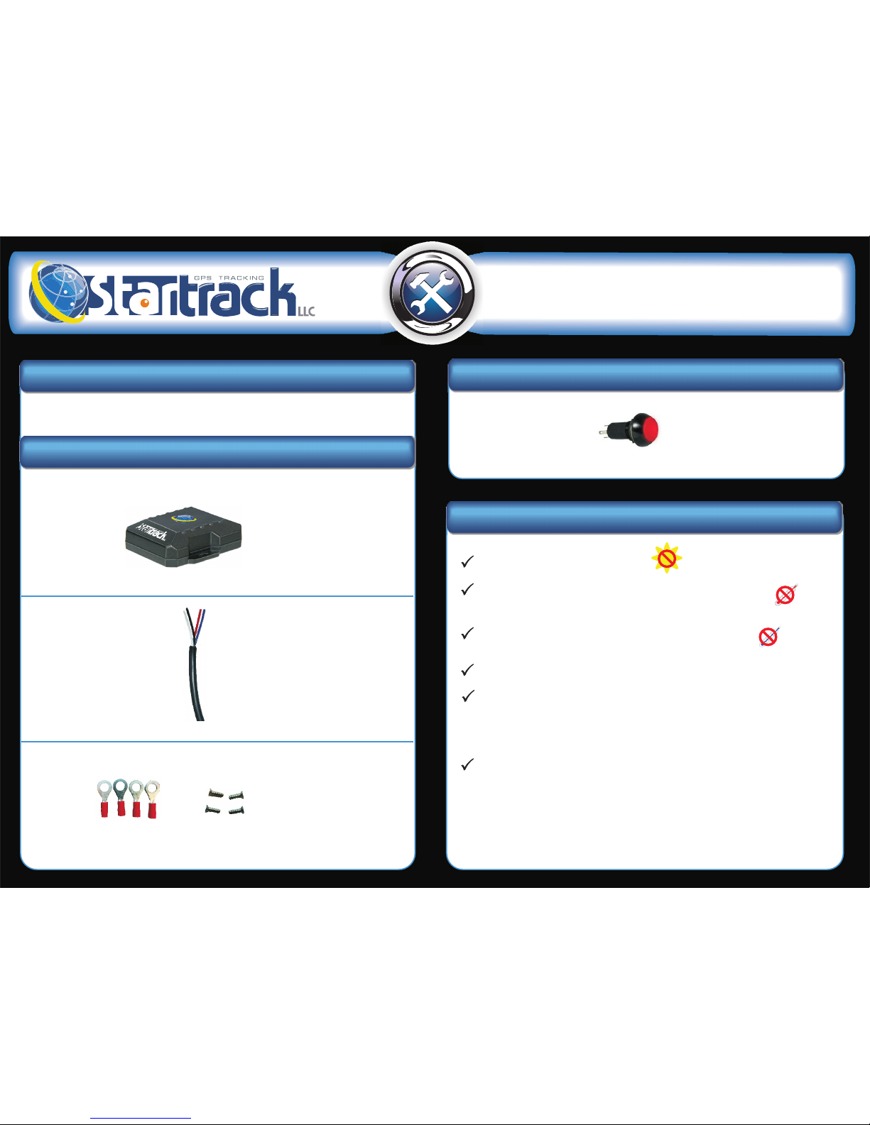
Check if you got the following Items to start your Installation.
Do not expose to Direct sun light.
Keep it Away from excessive heat sources like the motor or
the exhaust's path.
Keep it Away from excessive cold sources like a truck's
refrigerator or AC system.
Do not attached to a highly vibrating structure.
The
communication under normal vehicular conditions. The unit must
not be installed inside a metal structure that could act as a Faraday
cage which could lower the signal strength.
STTCK-5000 has an internal GSM antenna that will assure GPRS
The
optional external GPS antenna. When using the internal antenna,
the units must be located so that it has minimal metal obstructions
to the sky view and with the upper part facing up. It is recommended
to use the external GPS antenna in most cases.
STTCK-5000 has an internal GPS antenna, and a connector for an
1. Check List
Item Picture Description
STTCK-5000 STTCK-5000. We
highly recommend a
configured unit , to
avoid dealing with
troubles regarding
misconfiguration.
STTCK-5000 I/O Cables Check the PIN
description in
the following section,
for information about
voltage inputs, Digital
outputs and so on.
The STTCK-5000 comes
with 4 washers for better
wire connection and
4 screws to secure the
unit
Item Picture Description
Panic Button
(optional)
It is used as a local
tactile alarm
2. Precautions Before Installation
r
r
r
r
r
r
Quick Installation Guide
Washers & Screws
Page 4
3. Suitable Location for the Installation
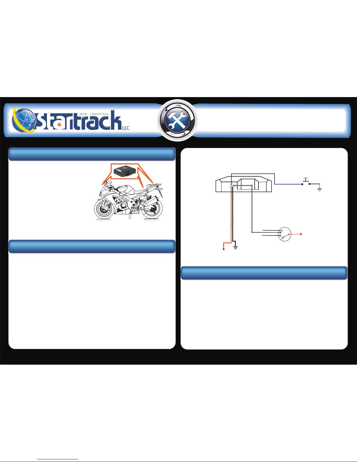
The unit's location can be underneath the
front, the seat or the back as shown to
the right. Also remember that there
shouldn't be any metal obstructing the
device view because of the internal
GPS & GSM antennas.
The antennas are located to the right
side of the device when looking at
it from the front, so keep this in mind
when positioning the device inside
the motorcycle.
4. Basic Installation
1. Identify the Power cables in the cable, Red for power (+12VDC or +24VDC)
Black for Ground, White for Ignition & Blue for Panic Button.
2. Connect the wires from the STTCK 5000 to the motorcycle.
a) Red: Power Source (+12VDC or +24VDC vehicle are supported)
This connection point should be fuse protected to not more
than 5 Amps
b) Black: Ground (Normally on the Vehicle chasis)
c) White: Ignition detection (Connected to the ignition's key
position that closes the circuit between the battery's positive
voltage and the vehicle's electrical system. Do not connect on
the start position.
Quick Installation Guide
Vehicle ignition switch
Start (4th position)
Run (3rd position)
Accesories (2nd position)
Off
+12 to +24
VDC
GND
White (Ignition)
Blue (Panic Button)
5. Installer Check List.
•Screw driver kit.
•Socket wrench set
•Allen wrenches Metric
•Fluke Meter (or some kind of VTVM)
•Utility knife with sharp blades
•Under dash light
•Soldering Iron and solder
•Ratchets and extensions
•Hot glue gun
•Crimpers
•Cutters (assortment)
•Tie Wrap
•Tape 3M super 33+
•Tape 3M super flex
•Contact cleaner
•Fuses
To heavy battery wire
GND
d) Blue(optional): Panic Button (If you want to use this feature put
one terminal of the push button connected to this wire, and the
other one to ground.
Panic Buttton
 Loading...