

Page 1
INSTINCT
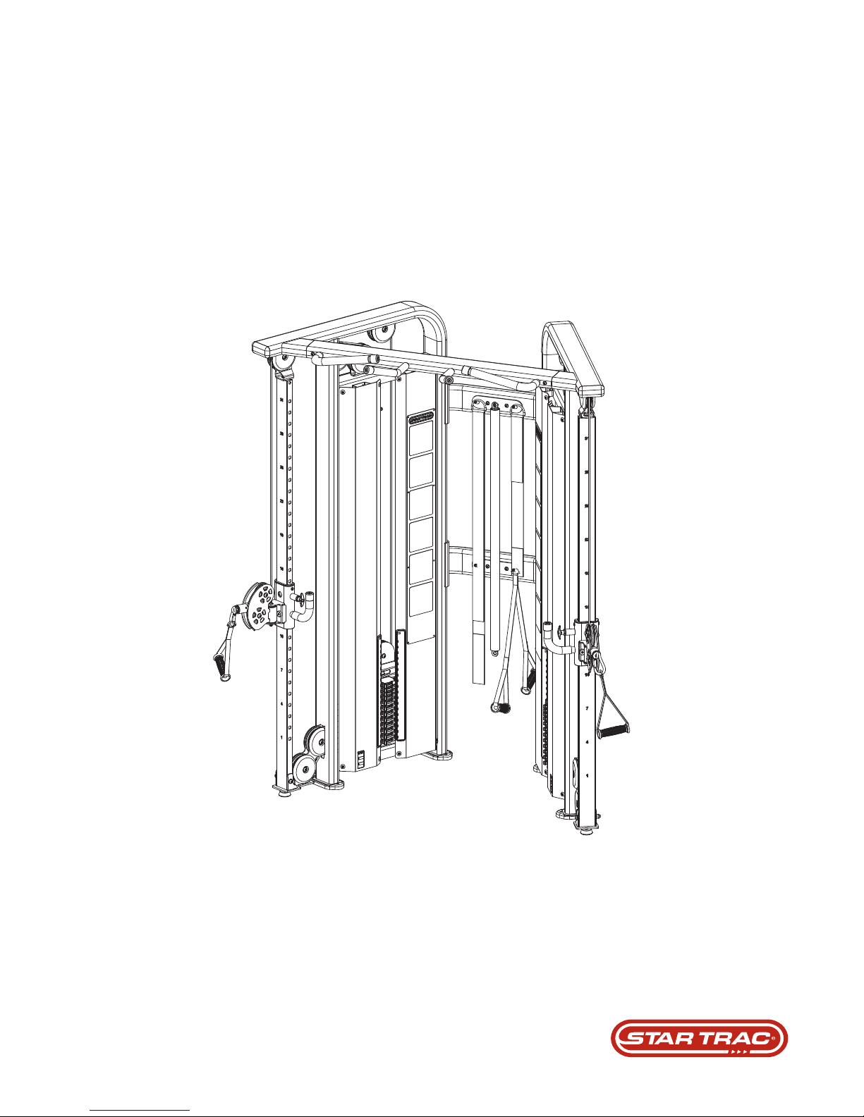
DUAL ADJUSTABLE PULLEY
IL-D2002
STRENGTH
TM
INSTALLATION INSTRUCTIONS
expect different
TM
TM
Designed to Inspire
Page 2

Copyright 2010. Star Trac by Core Industries, Inc. All rights reserved, including those to reproduce this
book or parts thereof in any form without first obtaining written permission from Star Trac.
Every effort has been made to keep this information current; however, periodically, changes are made to
the information herein, and these changes will be incorporated into new editions of this publication. All
product names and logos are trademarks of their respective owners. Printed in the USA.
Page 2
Page 3
INSTALLATION INSTRUCTIONS
REQUIRED TOOLS:
• •
• • • • • • • • • • • • • • • • • • •• • • • • • • • • • • •
• TORQUE WRENCH
• • •
GENERAL NOTES:
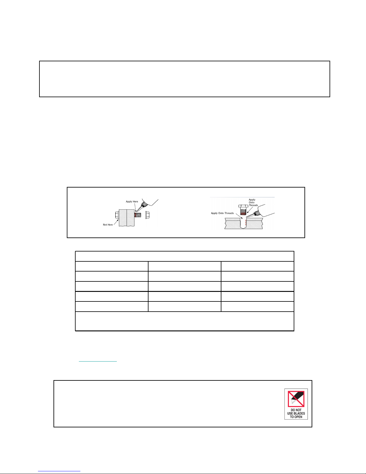
• Unless otherwise noted Loctite 242/243 or equivalent thread locker must be used on all threaded fasteners. (Do not
use thread locker when a Nyloc nut is used.)
• All Star Trac Strength equipment MUST be secured to the floor using either 10mm or 3/8in. (grade 5 minimum) bolts.
To accommodate this there are mounting holes located on every foot.
• This Installation Instructions Manual must be used in conjunction with the equipment’s Owner’s Manual. The Owner’s
manual describes equipment setup and instructs members on how to use it correctly and safely.
THREAD LOCKER APPLICATION: Clean all threads and holes, apply no more than 3-4 drops per bolt.
• • • • • • • • • • • • • • • • • • •• • • • • • • • • • • • • •• • • •
11• 5MM HEX KEY SOCKET
Thru Holes Blind Holes
Metric Steel Bolts Torque Specifications
Bolt Size Thread Pitch Torque, N-m (lbs-ft)
6mm 1.25 10-13.5 (8-10)
8mm 1.25 25.5-28.5 (19-21)
10mm 1.75 55.5-58 (45-48)
12mm 1.25 61-65 (45-48)
• Torque all hardware to values as specified above, unless noted otherwise.
• See Page 9 of this manual for fastener sizing information; for reference only.
• Note: All torque values are in N-m unless otherwise stated.
Should any component not be present or if you have any operational questions, please refer to your owner’s manual or on
the web @ www.startrac.com . Specifically refer to your Inspiration serial number and model number labeled on your
equipment.
PACKAGING REMOVAL:
Carefully remove all packaging materials that wrap the equipment. DO NOT USE A KNIFE OR BOX
CUTTER AS YOU MAY DAMAGE THE EQUIPMENT. At this time remove any sub-components
from the box and set aside for later assembly.
Page 3
Page 4
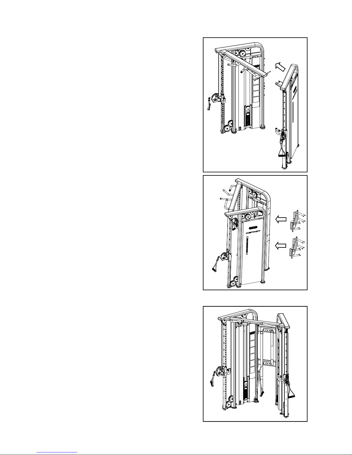
TOWER ASSEMBLY:
1. Stand one of the DAP towers upright and slide
the dip bar assembly onto its mounting sleeve.
Now slide the other DAP tower into place
using the dip bar assembly as a guide.
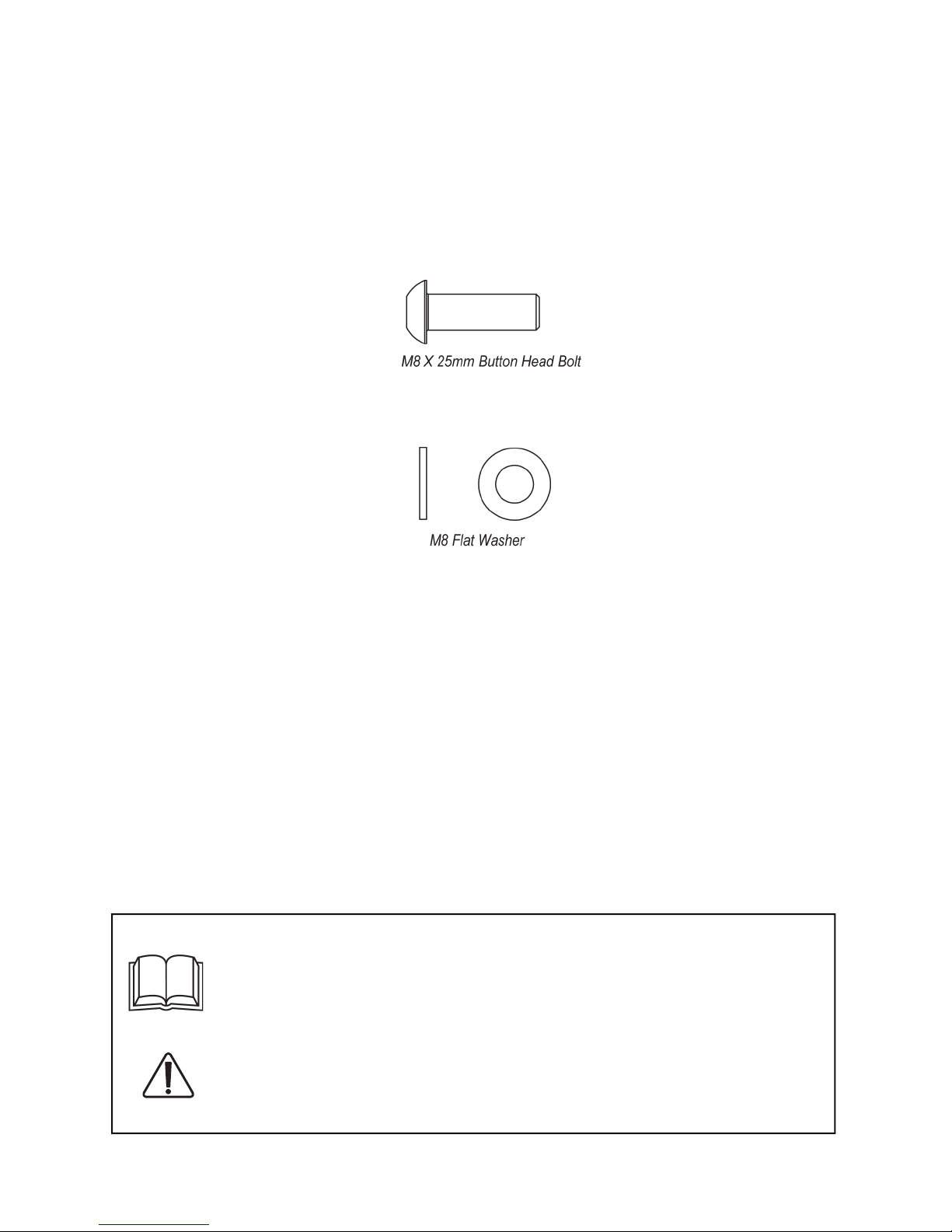
2. Locate and install the six (M8,25mm,Button
Head Bolts) and six (M8,Flat Washers) as
shown. Do not tighten bolts at this time.
3. Install the two rear DAP tower supports using
sixteen (M8,25mm,Button Head Bolts) and
sixteen (M8,Flat Washers).
4. After all bolts are installed use an M5 Hex key
socket and torque wrench to tighten all M8 bolts
from step one through step three.
HAND STRAP AND BODY STRAP INSTALLATION:
1. Hang the hand strap on the under hook.
2. Hang the body strap on the upper hook.
Page 4
Page 5
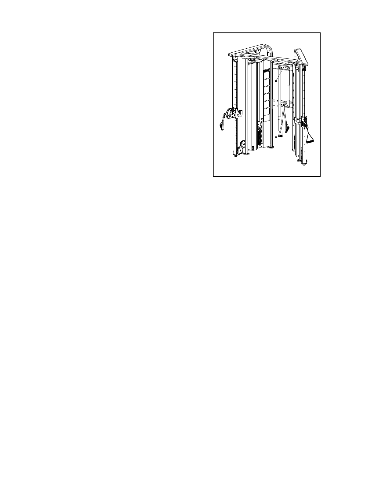
BAR ASSEMBLY INSTALLATION
1. Hang the bar assembly on the upper hook
as shown right picture.
.
Page 5
Page 6
HARDWARE GUIDE
Before using this product, it is essential to read the ENTIRE operations manual and ALL
installation Instructions. The Owner’s manual describes equipment setup and instructs
members on how to use it correctly and safely.
Health related injuries may result from incorrect or excessive use of exercise
equipment. Star Trac strongly recommends you to encourage you and your members to
discuss their health program or fitness regimen with a health care professional,
especially if you or they have
known health conditions.
WARNING!
not exercised
Page 6
for several years, are over 35, or have
Page 7

4400 North East
-
r
th
A
STE
expect different
TM
STAR
Vancouver, Wa
Telephone: (800) 228
Fax: (714)
www.sta
TRAC
7
ve.
300
shington 98662
6635, (714) 669-1660
508-3303
trac.com
Part No. 731-5704,June 2013
 Loading...