

Page 1

Treadmill Technical Manual
Last updated 03/06/2017 637-4504 Rev. B
Page 2

Safety Information
Tools
Product Details
E-TRx
E-TR
S-TRc
S-TRx
Power Requirements
Product Placement
Preventative Maintenance
Systems
Power
Display
Drive
Belt & Deck
Elevation
Maintenance Mode
Part Replacement Procedures
Running Belt
Deck / Deck Cushions
Rollers
EMI Filter
Motor Control Board
Drive Motor
Elevation Motor
Console
o LED
o LED Keypad / Display Electronics
o Embedded
o CCB
Troubleshooting
Last updated 03/06/2017 637-4504 Rev. B
Page 3

Safety Information
The following pages are intended to educate service technicians on the basic maintenance and
service actions for the StarTrac treadmill. By following the enclosed instructions and
maintenance schedule, you will extend the life of your equipment and help ensure it will withstand
hours of use in your home/facility.
Before working on this equipment, pay attention to the following warnings:
Read and understand the complete Owner's Manual.
Keep Owner's Manual for future reference.
Read and understand all warnings on this machine. If at any time the Warning stickers become loose,
unreadable or dislodged, contact Customer Service for replacement stickers.
Keep children away from this machine. Monitor them closely when near the machine. Parts that move and
appear dangerous to adults can appear safe to children.
Consult a physician before you start an exercise program. Stop exercising if you feel pain or tightness in your
chest, become short of breath, or feel faint. Contact your doctor before you use the machine again. Use the
values calculated or measured by the machine's computer for reference purposes only.
Before each use, examine this machine for loose parts or signs of wear. Do not use if found in this condition.
Pay special attention to the steps. Contact Customer Service for repair information.
Maximum user weight limit: 500lbs. (227kgs). Do not use if you are over this weight.
Do not wear loose clothing or jewelry. This machine contains moving parts.
Set up and operate this machine on a solid, level, horizontal surface.
Do not step off the machine until the belt has fully stopped.
Do not operate this machine outdoors or in moist or wet locations.
Keep at least 20” on each side and 48” from the back of the machine clear for easy egress/ingress. This is the
recommended safe distance for access and passage around and emergency dismounts from the machine.
Keep third parties out of this space when machine is in use.
Do not over exert yourself during exercise. Operate the machine in the manner described in this manual.
When the machine is put in a studio or club environment, it can only be used in areas where access and
control of the machine is managed by approved staff. The degree of management depends on the user's
ability to recognize and prevent danger to third parties during the exercise movement.
To decrease risk of burns, fire, electric shock, or injury to persons:
An appliance must not be left unattended when plugged in. Unplug from outlet when not in operation and
before you put on or remove parts.
Close supervision is necessary when this appliance is used by or near children or disabled persons.
Use this appliance only for its intended use as described in this manual. Do not use attachments that are
not recommended by the manufacturer.
Do not operate this appliance if it has a damaged cord or plug, if it is not working correctly, if it has been
dropped or damaged, or fallen into water. Return the appliance to a service center for examination and
repair.
Keep the cord away from heated surfaces.
Do not drop or put any object into any opening.
Do not use outdoors.
To disconnect, turn all controls to the off position, then remove plug from outlet.
Last updated 03/06/2017 637-4504 Rev. B
Page 4

Tools
Qty.
Name
Model
Manufacturer
Specifications
1
Multi-meter
Various
Digital, Continuity
1
Socket Set, SAE
Various
1/4" - 5/8"
1
socket Set, Metric
Various
4mm - 21mm
1
Socket driver
Various 1
Open end wrenches, SAE
Various
1/4" - 3/4"
1
Open end wrenches, Metric
Various
4mm - 17mm
1
Hex Bit Socket Set, SAE
Various
5/64 - 3/8
1
Hex Bit Socket Set, Metric
Various
4mm - 14mm
1
Torque Wrench
Various 1
Torque Wrench
Various
1+
Screwdriver Set, Phillips
Various
1+
Screwdriver Set, Flat
Various 1
Tape Measure
Various 1
Cold Chisel Set
Various 1
Ball Pin Hammer
Various
10 oz
1
Bearing Puller
Various
3-arm
1+
Rubber Mallet
Various
1
iPod
Apple
Video
1
TV Channel Modulator
Various
Ch.3/4 Output
1
Headphone
Standard
Various
Standard 3.5mm
1
Apple Composite AV Cable
Apple 1+
Compression F Connector
Wrench
LCCT-
SS59/11
DIGICON
25+
Compression F Connectors
DIGICON
DS6
DIGICON
1+
Cable Stripper
VH596
RCA 1+
Cable Torque Wrench
TW207-AH
Ripley
2
Coax Seal
#104
Coax-Seal
2
FISP - JTAG Programmer
JTAG
4D Electronics Ltd.
www.4delectronics.co.nz
1 USB - Flash Drive
Various
1 GB
1+
Stretch-wrap Cutter
400021
Highlight
1+
Furniture Dolly
Various
Rubber top
4
Motorcycle straps, adjustable
Various 1+
15 amp to 20 amp plug, adapter
Various
1
Loctite 680
Various
50
zip ties
4”
50
zip ties
8”
Last updated 03/06/2017 637-4504 Rev. B
Page 5
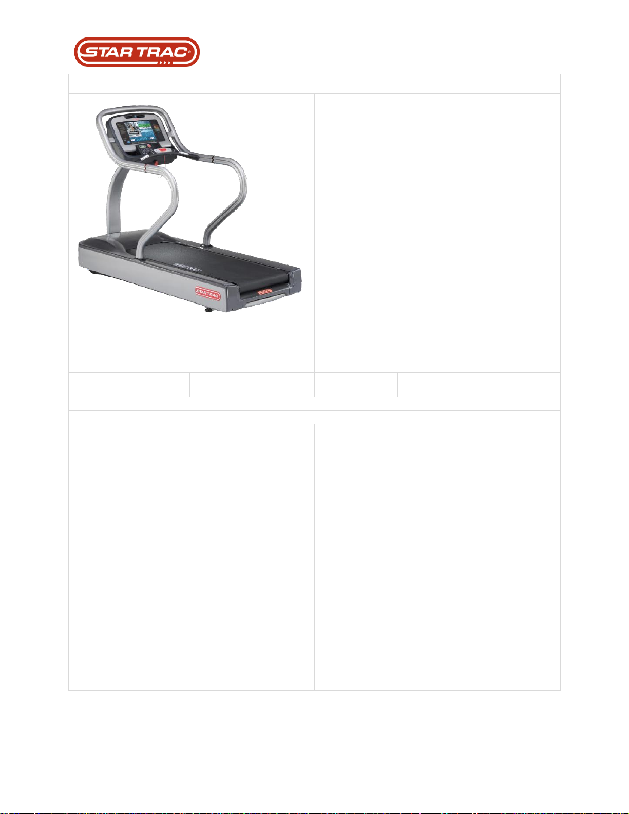
E-TRx
15” embedded HD touch screen aligns
user’s workout with their entry goals and
expectations with sophisticated and
intuitive programs and features
Integrated iPod® connectivity with music
and video allows users to display personal
content
Easily accessible Hot Bar® is located
closer to the user with one-finger speed
and elevation controls, integrated stop
button and contact heart rate grips
Star Trac Coach™ Over 1 million possible
workouts ensure a different workout every
time taking the ordinary treadmill
experience to a new level of engagement
never seen before
Soft Trac® triple cell cushioning system
provides maximum shock absorption
Centered dual-adjustable personal fans
create a more rewarding workout
20% max incline
User weight capacity 500 lbs. (227 kg)
Overall Weight
Running Surface
Width
Length
Height
477 lbs 216.4 kg)
60˝ x 21.5˝ (152 x 55 cm)
36˝ (91 cm)
85˝ (215 cm)
63˝ (160 cm)
Features and Specifications:
STEP-UP HEIGHT: 10” (25.5 cm)
FRAME: Custom aluminum uniframe
MOTOR DRIVE: 5 HP AC
ELECTRICAL: 110 volt, dedicated NEMA 5-20 cord; 220
volt, dedicated NEMA 6-15 cord (optional)*
CERTIFICATION: UL/CSA, CE, FCC, or CISPR
SUSPENSION: Soft Trac® triple cell neoprene rubber,
Deck System: Reversible 1” (2.5 cm) composite
fiberboard, waxing not required
ROLLERS: 3.5” (9 cm) sealed bearings
COLORS: Frame: Star Trac Silver, Shrouds: Slate Gray,
Accents: Black
INCLINE RANGE: 0 to 20% in 0.5% increments
SPEED RANGE: 0.5 to 15mph** (0.8 to 24 km/h**) in 0.1
mph (0.1 km/h) increments
HR MONITORING: Polar® Telemetry and Contact Heart
Rate System
DISPLAY: 15” embedded touch screen with high
definition TV and four workout views, including Progress
View, Track View, Heart Rate View, and Simple View
READOUTS: Dedicated: Speed and incline, time
elapsed, calories, calories/hour, pace (min/mile or km),
distance, course profile, heart rate, heart rate tracking,
1/4-mile motivational track, laps completed
PROGRAMS: 18 workouts including Dynamic Heart Rate
Control®, Constant Heart Control, Fitness Test (Modified
Balke Ware), Firefighter Test (Modified Gerkin Protocol),
ARMY Protocol, USMC Protocol, USAF Protocol, NAVY
Protocol, three custom workouts and Star Trac Coach™.
STANDARD FEATURES: Standard Features: Hot Bar
controls, personal entertainment system, personal
cooling fans, wrap-around Aero Bar, dedicated heart rate
display, safety lockout control, FitLinxx® certified
ENTERTAINMENT: E Series touch screen entertainment
system which includes 15” high definition LCD with touch
screen technology, NTSC/ATSC/QAM digital tuner or
PAL/SECAM tuner, integrated iPod® connector, USB
power port, coaxial cable connector at base
WARRANTY: Motor & MCB–5-year parts and labor;
Other parts–2-year parts, 1-year labor; Wear items–1year parts and labor; Headphone jack, iPod connector,
and USB port – 90 day parts, no labor (USA and Canada
only)** (Light Commercial warranty for all non-dues
paying facilities 3 years parts/labor)
Last updated 03/06/2017 637-4504 Rev. B
Page 6
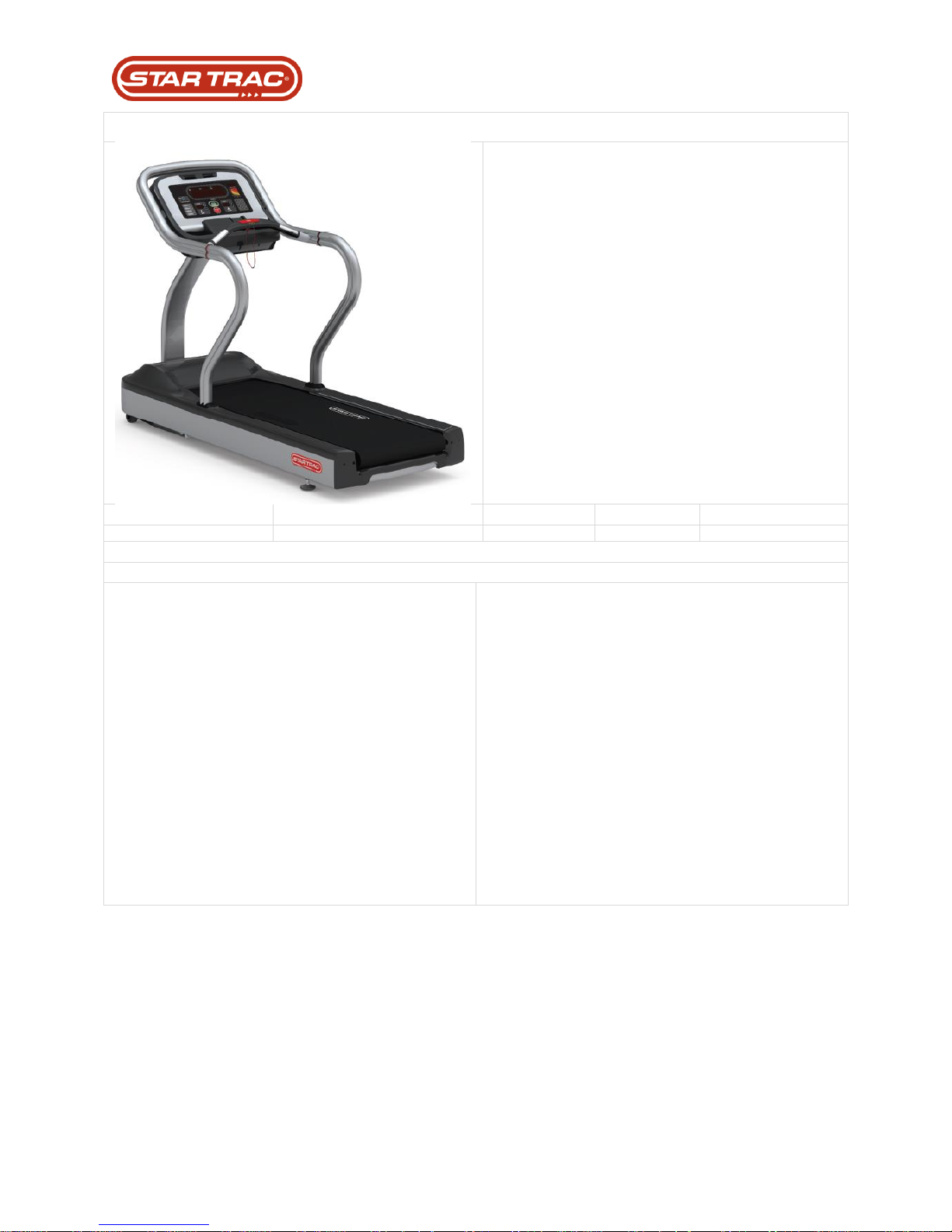
E-TR
Pre-wired for E Series PVS entertainment
system
User-friendly console and keypad feature
a large service scrolling message window,
user-specific workout programs, a
dedicated heart rate display, Polar®
telemetry and multiple cup and accessory
holder
Soft Trac® triple cell cushioning system
provides maximum shock absorption
5 HP AC Motor
Centered dual-adjustable personal fans
create a more rewarding workout
21.5” (54.6 cm) belt
9” (22.86 cm) step-up height
User weight capacity 500 lbs. (227 kg)
Overall Weight
Running Surface
Width
Length
Height
575.5 lbs (261.04 kg)
60˝ x 21.5˝ (152 x 54.6 cm)
32˝ (81.3 cm)
81˝ (206 cm)
59.77˝ (151.81 cm)
Features and Specifications:
STEP-UP HEIGHT: 9” (22.86 cm)
FRAME: Custom powder-coated steel uniframe
MOTOR DRIVE: 5 HP AC
ELECTRICAL: 110 volt, dedicated NEMA 5-20 cord; 220
volt, dedicated NEMA 6-15 cord (optional)
CERTIFICATION: UL/CSA, CE, FCC, or CISPR
SUSPENSION: Soft Trac® triple cell neoprene rubber,
Deck System: Reversible 1” (2.5 cm) composite
fiberboard, waxing not required
ROLLERS: 3” (7.6 cm) sealed bearings
COLORS: Frame: Star Trac Silver, Shrouds: Slate Gray,
Accents: Black
INCLINE RANGE: 0 to 15% in 0.5% increments
SPEED RANGE: 0.5 to 12.5mph (0.8 to 20 km/h) in 0.1
mph (0.1 km/h) increments
HR MONITORING: Polar® Telemetry and Contact Heart
Rate System
STEP-UP HEIGHT: 9” (22.86 cm)
FRAME: Custom powder-coated steel uniframe
MOTOR DRIVE: 5 HP AC
ELECTRICAL: 110 volt, dedicated NEMA 5-20 cord; 220
volt, dedicated NEMA
6-15 cord (optional)
CERTIFICATION: UL/CSA, CE, FCC, or CISPR
SUSPENSION: Soft Trac® triple cell neoprene rubber,
Deck System:
Reversible 1” (2.5 cm) composite fiberboard, waxing not
required
ROLLERS: 3” (7.6 cm) sealed bearings
COLORS: Frame: Star Trac Silver, Shrouds: Slate Gray,
Accents: Black
INCLINE RANGE: 0 to 15% in 0.5% increments
SPEED RANGE: 0.5 to 12.5mph (0.8 to 20 km/h) in 0.1
mph (0.1 km/h) increments
HR MONITORING: Polar® Telemetry and Contact Heart
Rate System
Last updated 03/06/2017 637-4504 Rev. B
Page 7
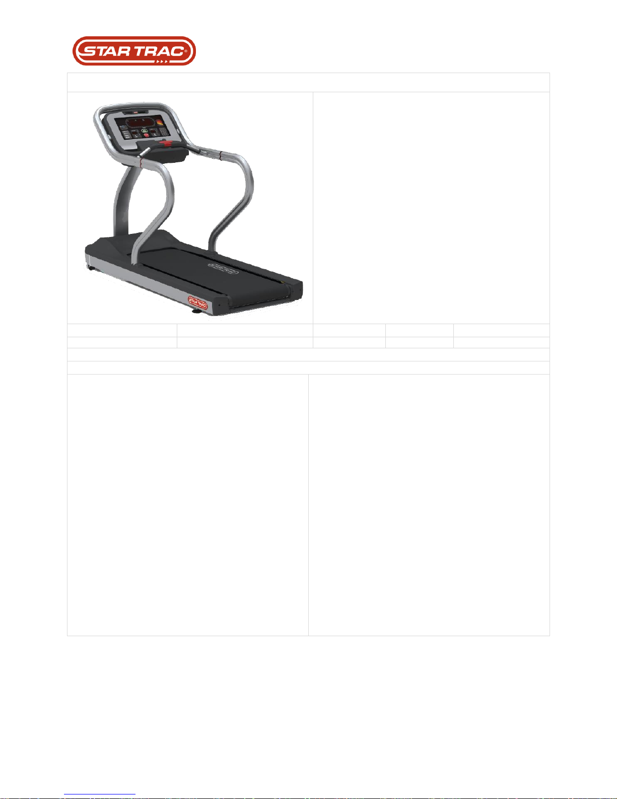
S-TRc
Pre-wired for E Series PVS entertainment
system
User-friendly console and keypad feature
a large service scrolling message window,
user-specific workout programs, a
dedicated heart rate display, Polar®
telemetry and multiple cup and accessory
holder
Soft Trac® triple cell cushioning system
provides maximum shock absorption
5 HP AC Motor
Centered dual-adjustable personal fans
create a more rewarding workout
20” belt
7” step-up height
User weight capacity 500 lbs. (227 kg)
Overall Weight
Running Surface
Width
Length
Height
533 lbs (241.7 kg)
60˝ x 20˝ (152 x 51 cm)
32˝ (81.3 cm)
81˝ (206 cm)
58˝ (147.3 cm)
Features and Specifications:
STEP-UP HEIGHT: 7” (17.8 cm)
FRAME: Custom powder-coated steel uniframe
MOTOR DRIVE: 5 HP AC
ELECTRICAL: 110 volt, dedicated NEMA 5-20 cord; 220
volt, dedicated NEMA 6-15 cord (optional)
CERTIFICATION: UL/CSA, CE, FCC, or CISPR
SUSPENSION: Soft Trac® triple cell neoprene rubber,
Deck System: Reversible 1” (2.5 cm) composite
fiberboard, waxing not required
ROLLERS: 3” (7.6 cm) sealed bearings
COLORS: Frame: Star Trac Silver, Shrouds: Slate Gray,
Accents: Black
INCLINE RANGE: 0 to 15% in 0.5% increments
SPEED RANGE: 0.5 to 12.5mph (0.8 to 20 km/h) in 0.1
mph (0.1 km/h) increments
HR MONITORING: Polar® Telemetry and Contact Heart
Rate System
DISPLAY: Intuitive, tactile response keypad with LED
technology
READOUTS: Large 8-character message window;
Dedicated: Time, distance, incline, speed, heart rate, 1/4mile motivational track, profile; Scrolling: calories,
METs, course profile
PROGRAMS: 12 programs including Dynamic Heart
Rate Control®, Constant Heart Rate Control, Quick Start,
Burn Calories, Manual, Increase Endurance, Fitness
Test (Modified Balke Ware), Firefighter Test (Modified
Gerkin Protocol)
STANDARD FEATURES: Personal cooling fans,
wraparound Aero Bar, dedicated heart rate display,
Entertainment Solutions Ready, Safety Lanyard
ENTERTAINMENT: Pre-wired for S Series PVS
entertainment system
WARRANTY: Commercial warranty: 2-year parts
warranty, 1-year labor warranty, 5-year parts and labor
warranty on the motor and motor control board; Light
commercial setting: 3-year warranty on parts and labor,
5-year parts and labor warranty on the motor and motor
control board (USA and Canada only)** (Light
Commercial warranty for all non-dues paying facilities 3
years parts/labor).
Last updated 03/06/2017 637-4504 Rev. B
Page 8
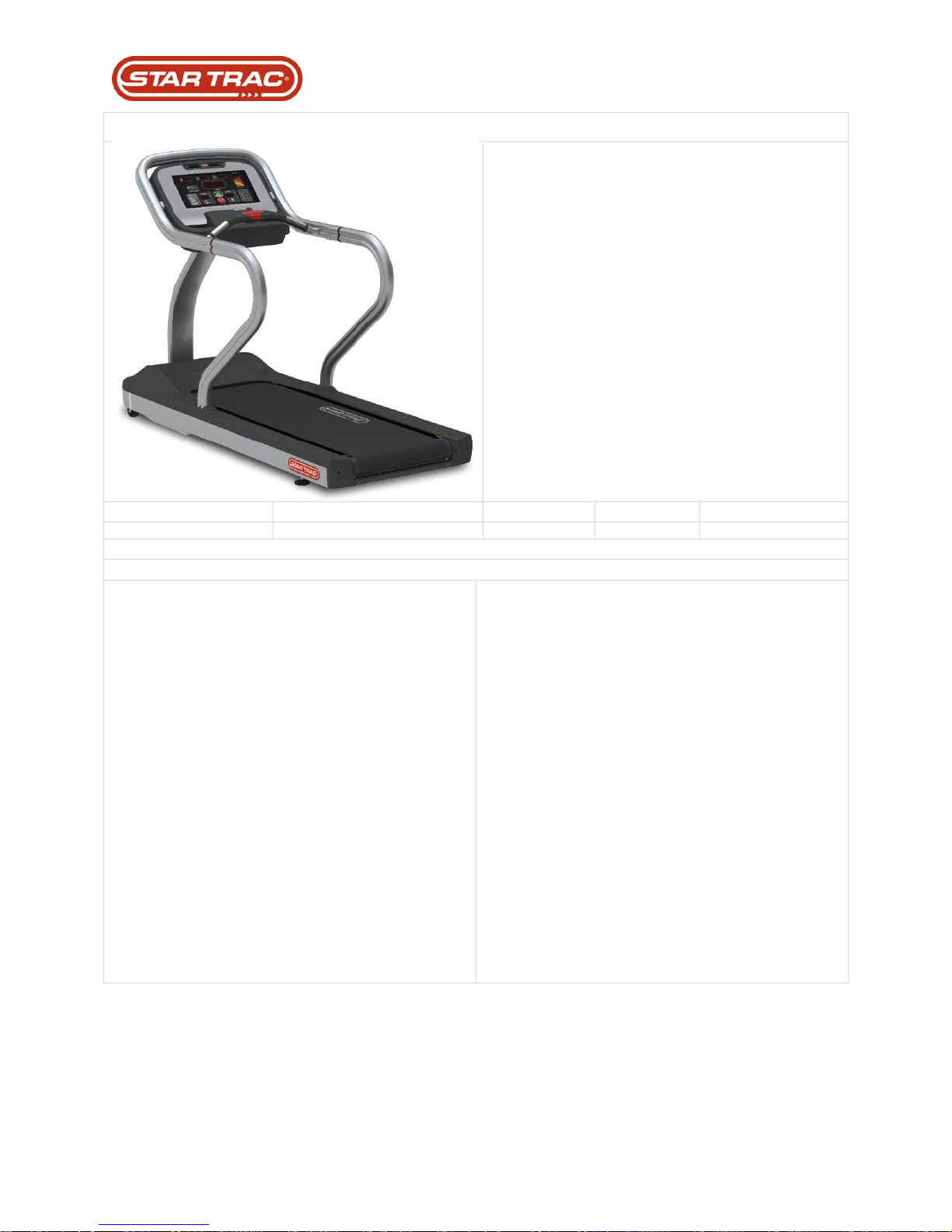
S-TRx
Pre-wired for E Series PVS entertainment
system
User-friendly console and keypad feature
a large service scrolling message window,
user-specific workout programs, a
dedicated heart rate display, Polar®
telemetry and multiple cup and accessory
holder
Soft Trac® triple cell cushioning system
provides maximum shock absorption
3 HP DC Motor
Centered dual-adjustable personal fans
create a more rewarding workout
20” belt
7” step-up height
User weight capacity 500 lbs. (227 kg)
Overall Weight
Running Surface
Width
Length
Height
514 lbs (233.2 kg)
60˝ x 20˝ (152 x 51 cm)
32˝ (81.3 cm)
81˝ (206 cm)
58˝ (147.3 cm)
Features and Specifications:
STEP-UP HEIGHT: 7” (17.8 cm)
FRAME: Custom powder-coated steel uniframe
MOTOR DRIVE: 3 HP DC
ELECTRICAL: 110 volt, dedicated NEMA 5-20 cord; 220
volt, dedicated NEMA 6-15 cord (optional)
CERTIFICATION: UL/CSA, CE, FCC, or CISPR
SUSPENSION: Soft Trac® triple cell neoprene rubber,
Deck System: Reversible 1” (2.5 cm) composite
fiberboard, waxing not required
ROLLERS: 3” (7.6 cm) sealed bearings
COLORS: Frame: Star Trac Silver, Shrouds: Slate Gray,
Accents: Black
INCLINE RANGE: 0 to 15% in 0.5% increments
SPEED RANGE: 0.5 to 12.5mph (0.8 to 20 km/h) in 0.1
mph (0.1 km/h) increments
HR MONITORING: Polar® Telemetry and Contact Heart
Rate System
DISPLAY: Intuitive, tactile response keypad with LED
technology
READOUTS: Large 8-character message window;
Dedicated: Time, distance, incline, speed, heart rate, 1/4mile motivational track, profile; Scrolling: calories,
METs, course profile
PROGRAMS: 12 programs including Dynamic Heart
Rate Control®, Constant Heart Rate Control, Quick Start,
Burn Calories, Manual, Increase Endurance, Fitness
Test (Modified Balke Ware), Firefighter Test (Modified
Gerkin Protocol)
STANDARD FEATURES: Personal cooling fans,
wraparound Aero Bar, dedicated heart rate display,
Entertainment Solutions Ready, Safety Lanyard
ENTERTAINMENT: Pre-wired for S Series PVS
entertainment system
WARRANTY: Commercial warranty: 2-year parts
warranty, 1-year labor warranty, 5-year parts and labor
warranty on the motor and motor control board; Light
commercial setting: 3-year warranty on parts and labor,
5-year parts and labor warranty on the motor and motor
control board (USA and Canada only)** (Light
Commercial warranty for all non-dues paying facilities 3
years parts/labor).
Last updated 03/06/2017 637-4504 Rev. B
Page 9
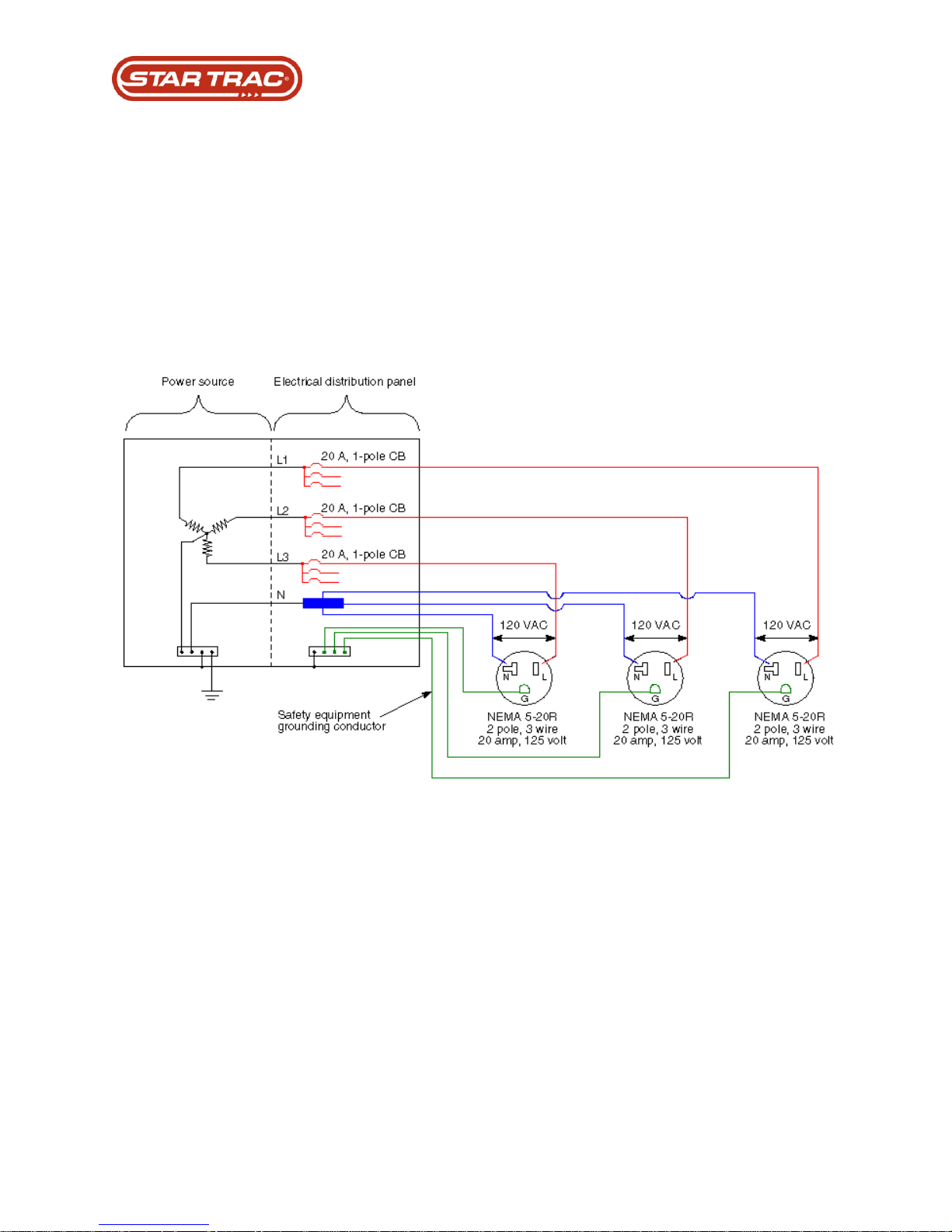
Power Requirements
Treadmill Dedicated Circuit Requirement:
Star Trac requires a 20 amp dedicated circuit and dedicated neutral for each treadmill installed
and operated. Each treadmill requires an outlet of which line and neutral contacts are wired to
the electrical power distribution box (circuit breaker box) with dedicated wires. Both the line and
neutral wire from an outlet for a treadmill shall be isolated from all other outlet contacts other
than the connection at the electrical power distribution box. The neutral bar of the electrical
power distribution box requires a connection to the earth ground.
Furthermore, there shall be no other electrical device operated off this circuit; just the single
treadmill. The earth ground connection of the outlet may be shared with other outlets’ earth
ground connections through either metal conduit or ground wire.
Each dedicated circuit requires 12 gauge wire for the line and neutral wires for runs less than
100 feet, as measured from the circuit breaker to the termination of the plug (outlet) connecting
to the treadmill. Runs greater than 100 feet require 10 gauge wires, and a run from a circuit
breaker shall not be greater than 200 feet.
Failure to meet these requirements may cause intermittent treadmill shut-down and potential
damage to the treadmill’s electronic components, and consequently, void the warranty.
Last updated 03/06/2017 637-4504 Rev. B
Page 10
Product Placement
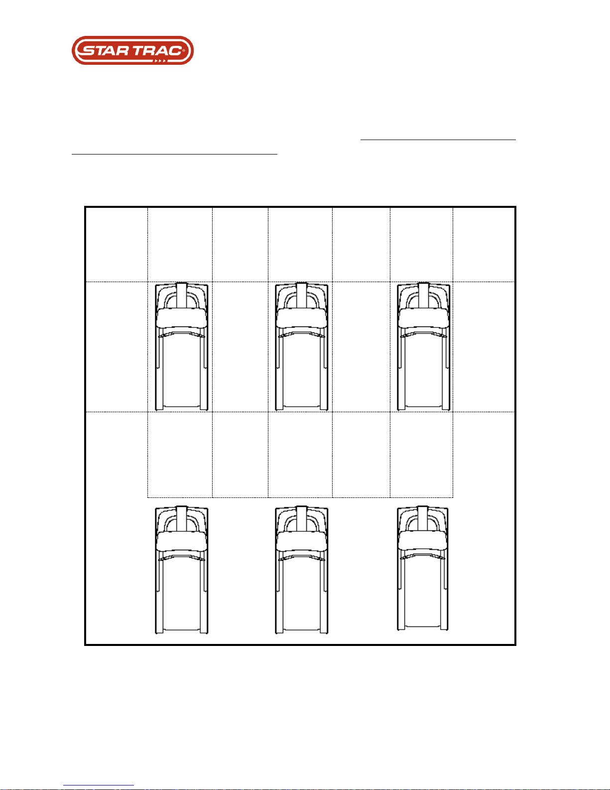
Star Trac recommends that treadmills be spaced a minimum of 20.0 inches (0.5 m) apart to
allow safe and easy ingress and egress. More importantly, there must be at least 48 inches
(1.25 m) of free space behind the treadmill.
The E-Series treadmill measures: 85” l by 36.0” w (215.9 x 91.5cm). See the following graph for
proper equipment spacing requirements:
Last updated 03/06/2017 637-4504 Rev. B
Page 11
Daily
Weekly
Monthly
Yearly
Wipe Down all Surfaces
X
Wipe Running belt with Dry Cloth
X
Elevate Unit and Vacuum underneath
X
Check Belt Tracking to assure belt stays centered
X
Check Condition of Power Cord
X
Inspect and Clean underside of running belt
X
Check drive belt tension
X
Check Running belt tension, adjusting if needed
X
Check all settings and Keypad Performance
X
Vacuum under shroud being careful around Electrical
Assy
X
Unplug unit and check all power connections including
speed sensor
X
Calibrate Elevation & Speed
X
Check Belt and Deck Condition and replace if wear found
X
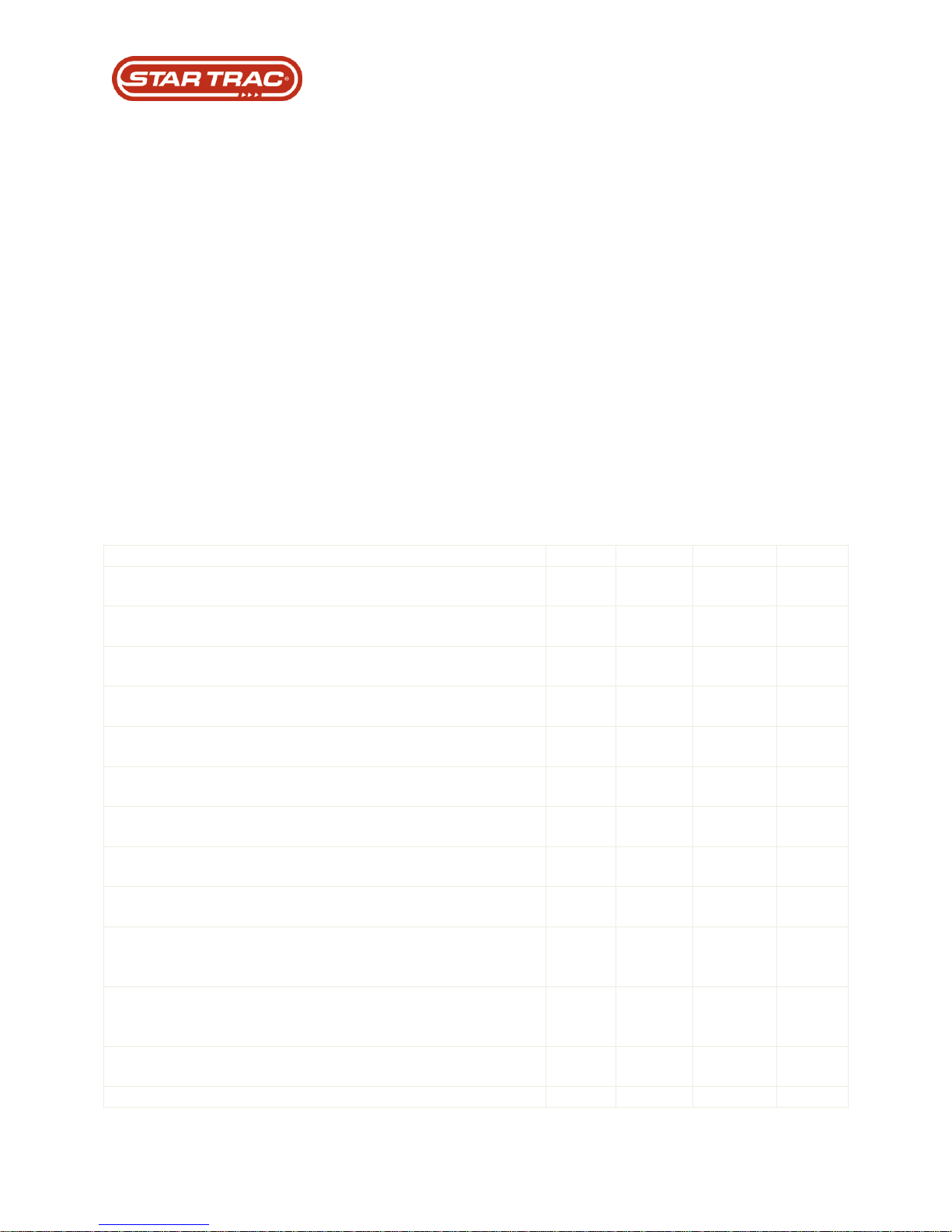
Preventative Maintenance
This section provides a list of factory recommended PM requirements. Long-term effects and
cost comparisons usually favor following a regular preventative maintenance schedule over
performing maintenance actions only when the system fails.
Preventative Maintenance Cautions
While maintaining equipment you will want to avoid spraying any liquids directly onto any surface
of the unit. Always spray cleaning solutions onto a clean towel first then wipe the unit.
While vacuuming the floor area using an upright vacuum, avoid getting the power cord caught in
the beater-brush of the vacuum.
Disconnect the power cord from the wall before vacuuming under the shroud.
Use extreme caution while vacuuming around wires and/or electrical components under the
shroud.
Do not attempt to clean the running belt with a mop
Do not apply any cleaners, protectants or solutions onto the running belt (i.e. Armor All,
SlickStuff, belt dressing, etc.)
Maintenance Actions:
Last updated 03/06/2017 637-4504 Rev. B
Page 12

Treadmill Systems
Power System
The power system supplies AC and DC voltage to different components of the treadmill. There
are two parts of the power system, external power and internal power.
There are two sub-systems:
External
Internal
External
The external power is anything outside of the treadmill that supplies power.
Components:
Breaker Box
Wall Breaker
Power Lines
Dedicated/isolated lines
Neutral Line
Hot Line
Ground Line
Receptacle
Internal Power
The internal power is the components of the treadmill that are involved with power distribution.
Components:
Power Cord
On/Off Switch
Onboard Circuit Breaker
EMI Filter
MCB
Power Supply
Data Cable
Display Electronics
Last updated 03/06/2017 637-4504 Rev. B
Page 13
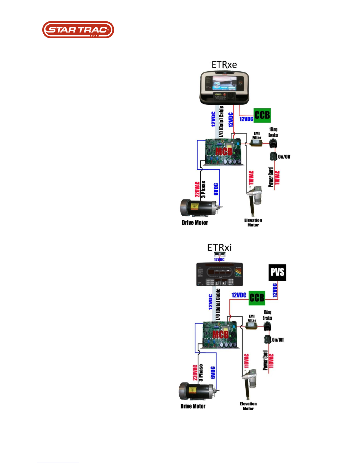
1. AC power goes from the
breaker box, through the
circuit breaker and power
lines to the power outlet.
2. AC power continues up
through the power cord,
through the onboard circuit
breaker, on/off switch, and
EMI filter to get to the MCB.
3. The MCB converts the
power to 12.6 volt VDC to
send up the display cable
to power up the display
electronics.
4. The MCB doubles the
incoming voltage (110 volt
systems only) and sends
220 VAC to the power the
drive motor. The MCB also
sends 6 VDC to power the
RPM sensor.
5. The MCB sends VAC to
power the elevation motor.
The power being sent will
depend on the input voltage.
110 VAC treadmills have a
110 volt elevation motor.
220 VAC treadmills have a
220 VAC elevation motor.
The MCB also sends 5 VDC
to the elevation sensor
(potentiometer).
6. The MCB passes along the
input VAC to the power
supply. The power supply
then converts the input
voltage to 12 VDC and
sends it up to the display
electronics to power the
fans (PVS kit or embedded
touch screen).
Power Flow Diagrams
Last updated 03/06/2017 637-4504 Rev. B
Page 14

Display System
The display system controls and commands most of the functions of the treadmill. It is the user
interface and the brain of the treadmill.
There are five sub systems:
1. Treadmill Operation
2. Watch Dog
3. Personal Cooling Fans
4. Heart Rate
5. Hot Bar/Warm Bar
Treadmill Operation
Treadmill operation is those functions and components that the user interacts with while working
out on the treadmill.
Components:
Main Keypad (Display Panel)
Display Electronics
Data Cable
Watch Dog
The watch dog is the circuit/software inside the display electronics that monitors the different
systems in the treadmill. If there are any anomalies, the watch dog triggers any of the various
codes that will show up on the screen.
Components:
Display Electronics
Personal Cooling Fans
This system is used to keep the users cool.
Components:
Display electronics
Fan Keypad
Fans
Last updated 03/06/2017 637-4504 Rev. B
Page 15

Heart Rate
The users have 2 types of heart rate to use, contact or Polar. Contact heart rate is used by
grabbing onto to the metal contacts on the hot/warm bar. Polar is a wireless system that
requires the user to wear the Polar chest strap.
Components:
Display Electronics
Contact Heart Rate Board
Contact Heart Rate Cables
Contact Heart Rate Grips
Polar Receiver
Hot /Warm Bar
The Hot/Warm bar is the bar that is right in front of the user that has multiple functions and
components.
Warm Bar Components:
Stop Button
Emergency Stop (lanyard)
Contact Hear Rate Grips
Hot Bar Components:
Stop Button
Emergency Stop (lanyard)
Contact Heart Rate Grips
Speed Control
Elevation Control
Headphone jack (for units with entertainment)
Last updated 03/06/2017 637-4504 Rev. B
Page 16
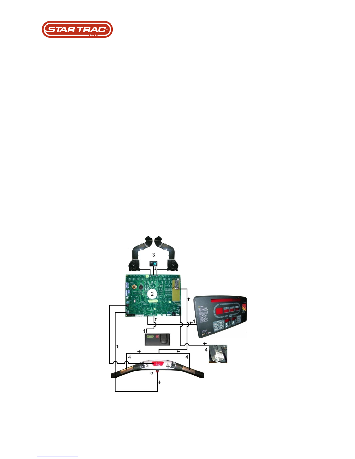
1. The user presses the keypad to select programs, speed, elevation etc. Those
keystrokes are received by the display electronics which sends the necessary requests
down the data cable to the MCB.
2. The watch dog is a part of the display electronics that monitors the systems of the
treadmill and will shut down the system if there are any anomalies.
3. The user presses the fan keypad to turn the fans on/off or change the speeds. The
display electronics receives the signals and sends the appropriate VDC to the fans.
4. The user grips the contact heart rate grips. A small amount of voltage is sent through
the grips and wires to the contact heart rate board. The contact heart rate board
calculates the Beats Per Minute (BPM) and sends this information to the display
electronics. If the user is wearing a Polar chest strap, signals from the strap will be
received by the Polar receiver. Those signals are sent to the display. The display will
display the BPM of the user’s heart.
5. When the user presses the stop button, the circuit opens (confirm that) and the display
electronics triggers the treadmill to: (a) pause on the first press, (b) end the program on
the second press and (c) give a ‘NO STOP’ code if the key is held for longer than 2
number of seconds. If the lanyard is pulled, the emergency stop circuit opens up and a
signal is sent to the MCB to cut power to the drive circuit. The message “EMERGENCY
STOP, PRESS STOP TO RESET TREADMILL” will appear on the display electronics.
Display System Power Flow
Last updated 03/06/2017 637-4504 Rev. B
Page 17

Drive System
The drive system is what makes the treadmill running belt move as well as sends feedback to
the display for keeping track of speed.
There two sub systems:
Drive Power
Feedback
Drive Power
Drive power is the VAC going to the drive motor to make it turn.
Components:
Display Electronics
Data Cable
MCB
Drive Motor
Feedback
Feedback is what the display uses to make sure the speed is what the user commanded.
Components:
RPM Sensor
MCB
Data Cable
Display Electronics
Last updated 03/06/2017 637-4504 Rev. B
Page 18
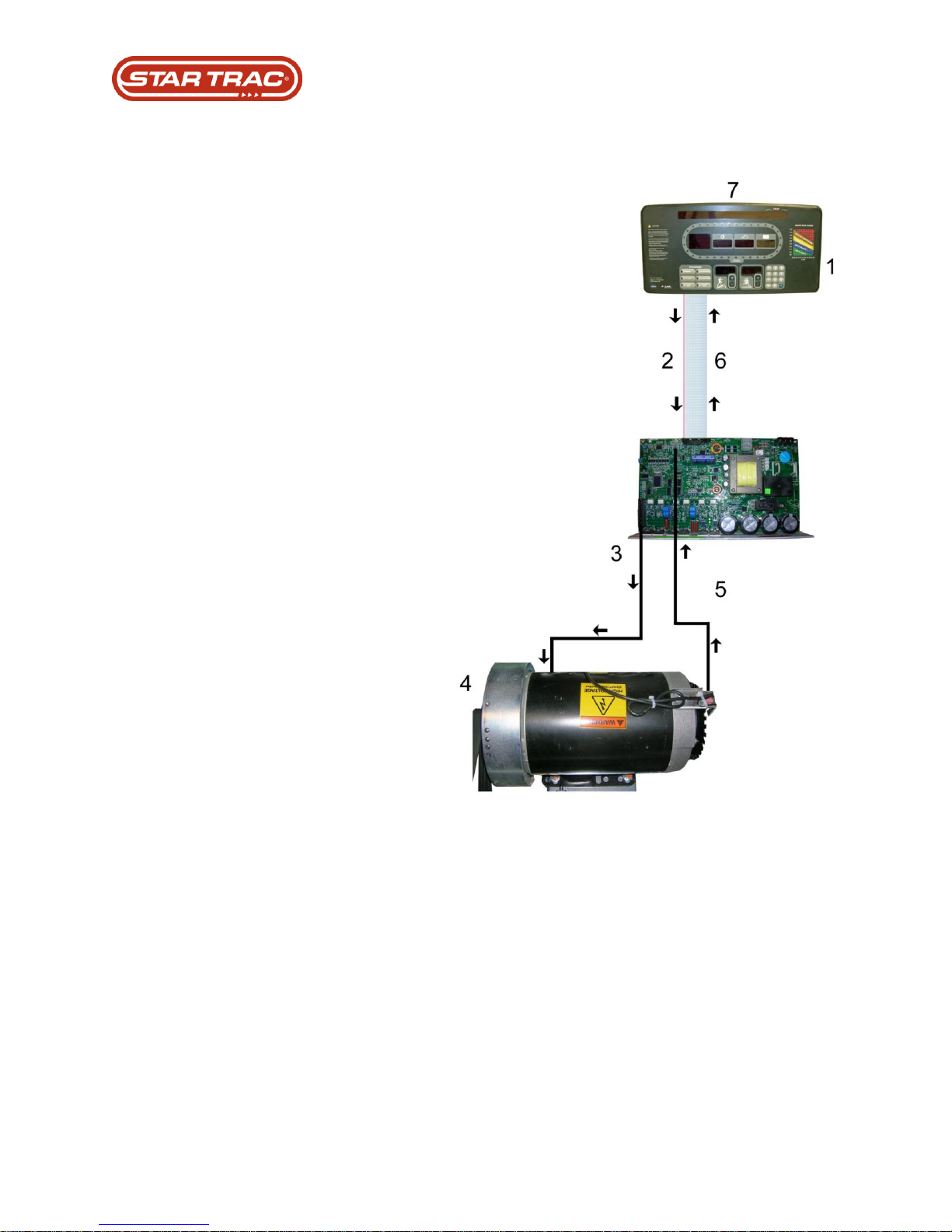
1. The user enters what speed
they want the treadmill to go
by pressing the speed keys or
entering the desired speed on
the number keypad.
2. The display electronics
registers the requests and
send information down to the
MCB.
3. The MCB sends VAC to turn
the drive motor.
4. The drive motor pulley is
connected to the headroller..
5. As the drive motor turns the
RPM sensor signal is sent to
the MCB.
6. The MCB sends the signal
back to the display
electronics.
7. The display electronics
calculates that information to
determine the speed of the
drive motor. If the drive
motor is running too fast/slow,
the display will send signals to
the MCB to adjust the voltage
going to the drive motor until
the speed is correct.
Drive System Power Flow
Last updated 03/06/2017 637-4504 Rev. B
Page 19
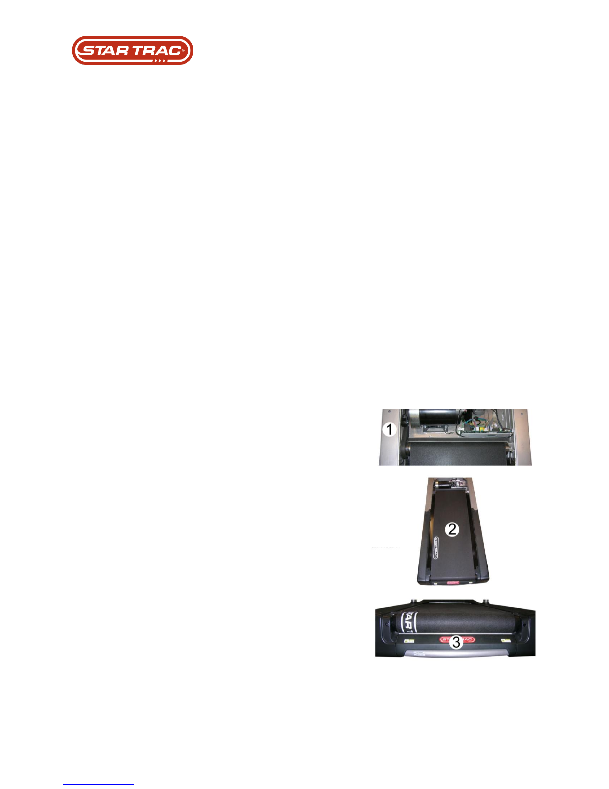
1. The drive belt connects the drive motor
to the headroller.
2. The tailroller is used for tensioning and
tracking of the running belt.
3. The running belt goes around the two
rollers and the deck. The deck is the hard
surface that the running belt slides on.
Belt & Deck System
The belt and deck system is the main function of the treadmill.
There two sub systems:
Rollers
Belt and Deck
Rollers
The rollers are used to make the belt rotate. It also applies tension and tracking for the belt.
Components:
Drive Belt
Headroller
Tailroller
Belt and Deck
Belt and deck are two of the wear items in the system. The user runs on the belt and deck.
Components:
Running belt
Deck
Last updated 03/06/2017 637-4504 Rev. B
Page 20

Elevation System
The elevation system controls the incline of the treadmill.
There two sub systems:
Elevation Motor
Elevation Sensor
Elevation Motor
The elevation motor is the muscle that makes the incline go up and down once it has received
signals from the display.
Components:
Display Electronics
Data Cable
MCB
Elevation Motor
Elevation Sensor
The elevation sensor is also known as the elevation potentiometer and is a part of the elevation
motor. It provides incline location feedback to the treadmill console.
Components:
Elevation Motor
MCB
Data Cable
Display Electronics
Last updated 03/06/2017 637-4504 Rev. B
Page 21
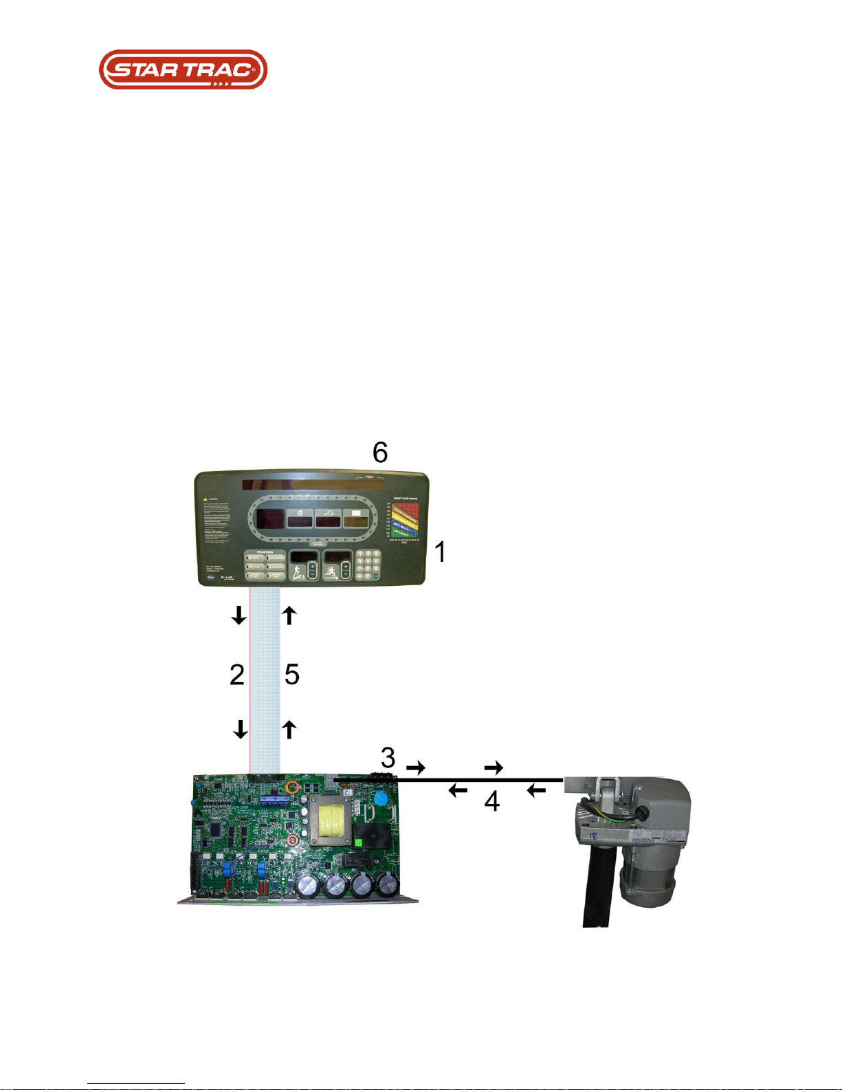
1. The user enters the desired elevation by pressing the elevation keys on the display.
2. The display sends a signal down to the MCB through the data cable.
3. The MCB will send the appropriate amount of AC voltage to the elevation motor to
make the incline go up or down. The MCB also sends a constant 5 volts DC to the
elevation potentiometer (pot).
4. As the elevation motor turns, the elevation pot’s voltage changes. That voltage is sent
back to the MCB.
5. The MCB sends to elevation pot voltage up the data cable and to the display.
6. The display will calculate what the incline number is based on the voltage being
received and the min/max values set for the incline to determine the current incline
position.
Elevation System Power Flow
Last updated 03/06/2017 637-4504 Rev. B
Page 22
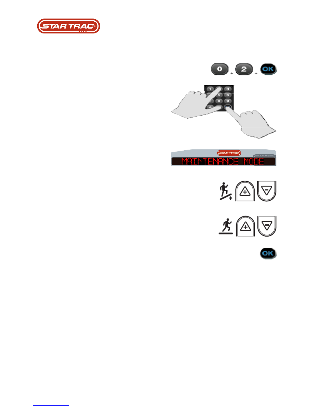
LED Console:
To enter Maintenance Mode, press the 0, 2,
and OK keys all together at once.
A beep will sound and the console will say
Maintenance Mode.
Use the Elevation up/down keys to change
between Maintenance Mode options.
Use the Speed up/down keys to edit the
options.
Use the OK button to enter, or save.
Maintenance Mode
Last updated 03/06/2017 637-4504 Rev. B
Page 23
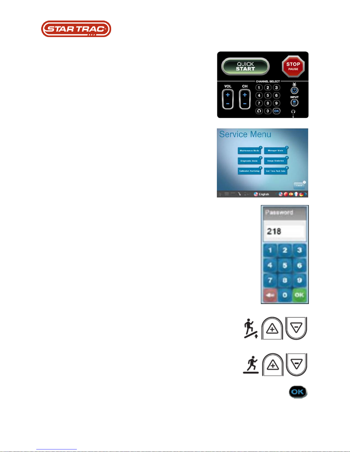
Embedded Console:
To enter the Service Menu, press the Vol +,
Ch+, and 3 keys all together at once.
Press the option on the touchscreen, or press
the number option you want to select on the
keypad.
The embedded console password is 218.
Use the Elevation up/down keys to change
between Maintenance Mode options.
Use the Speed up/down keys to edit the
options.
Use the OK button to enter, or save.
Last updated 03/06/2017 637-4504 Rev. B
Page 24
Part Replacement: Running Belt
Troubleshooting that must be done PRIOR to replacement:
1. DFR code 800
2. Confirm that the running belt logo ( STARTRAC ) is not 75% worn out
3. Confirm that the running belt is not over tensioned
4. Confirm that the running belt does not slip ( use stomp test )
5. Confirm that the running belt is aligned with the roller
6. Remove drive belt and check for roller noise
Adjustment requirements after replacement:
1. Required running belt installation
2. Required head roller replacement
Testing requirements after replacement:
1. Confirm that the installation test procedure is done
Running Belt Tension:
Proper running belt tension and tracking are important to maintain the performance and life of
the belt. It is recommended to follow the proper tracking and tensioning procedure whenever
running belt or deck is replaced, or as needed.
Tensioning Frequency:
After 1,000 Miles, or 1 Month. Or whichever comes first.
6,000 Miles, or 6 Months
12,000 Miles, or 12 Months
18.000 Miles, or 18 Months
24,000 Miles, or 24 Months
30,000 Miles or 30 Months
Belt Alignment:
Last updated 03/06/2017 637-4504 Rev. B
Page 25
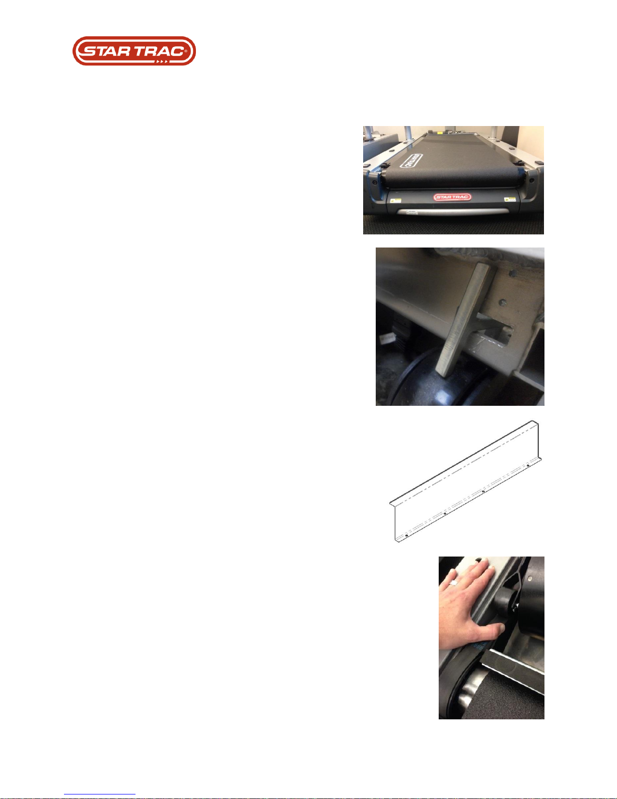
1. Remove the front and side bed covers from
the machine.
2. Loosen and remove the two bolts that hold
the tail roller onto the machine chassis.
Remove the tail roller from between the belt
and set to the side.
3. Pull and turn the T-pin idler pulley to remove
tension on the drive belt.
Caution pinch points.
4. Using a long phillips head screwdriver
remove the 4 screws that hold the head roller
finger guard in place.
5. Walk the drive belt off of the headroller pulley.
Remove belt from small pulley on motor.
Part Replacement: Running Belt
Procedure:
Last updated 03/06/2017 637-4504 Rev. B
Page 26
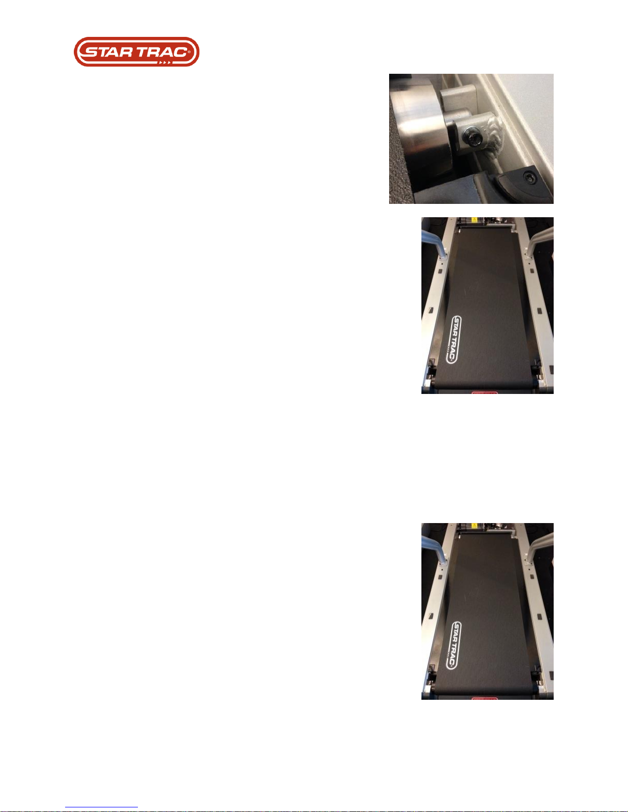
6. Loosen and remove the bolt that connects the
head roller to the chassis of the machine.
7. Remove the head roller and drive belt from
between the running belt and set to the side.
8. Loosen the deck retention rods at the 4
corners of the deck.
9. Remove belt and deck from chassis of
machine.
10. Flip deck so that the unused side is face up.
11. Replace new belt. Ensure arrows on the Star
Trac logo are oriented in the direction the belt
will move.
12. Replace the belt and deck onto the chassis
and fasten the 4 corner deck retention rods.
Last updated 03/06/2017 637-4504 Rev. B
Page 27
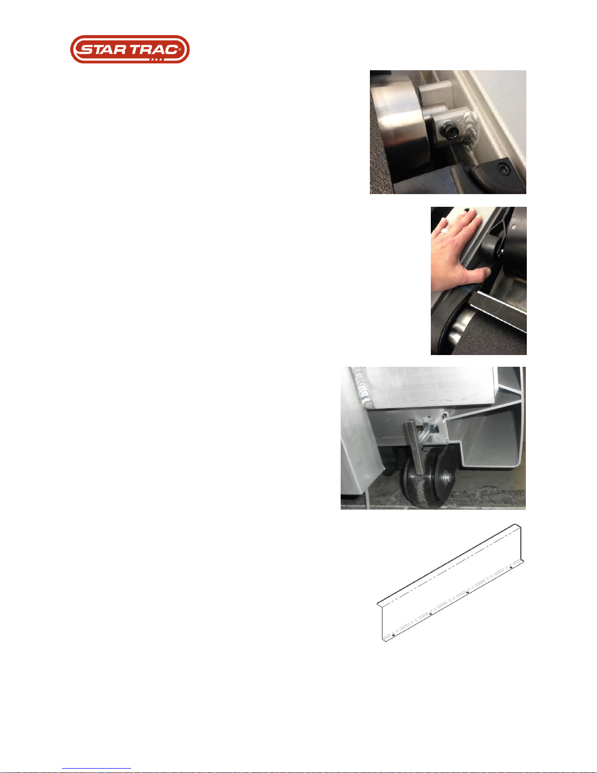
13. Replace head roller through the belt and
mount into the chassis of the machine.
Ensure drive belt is on the head roller before
mounting it.
14. Walk drive belt onto head roller and tail roller
pulleys.
15. Tension idler t-pin handle.
16. Replace head roller finger guard onto the
chassis of the machine.
Last updated 03/06/2017 637-4504 Rev. B
Page 28
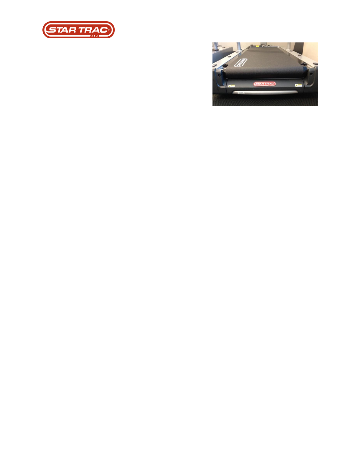
17. Replace tail roller through the belt and mount
to the chassis of the machine with the two
bolts.
Tension bolts equally, as they are responsible
for overall belt tension as well as tracking.
18. Ensure proper tracking and re-tension belt
using stomp test.
Adjustments:
The running belt and its headroller, drive belt, tailroller, and running deck are designed to be
self-centering, slip-free, and smooth-operating without the need for frequent adjustments.
Running belt sideward movement, slipping, or grinding after extended use, or thumping during
initial use, may be corrected by the following procedures:
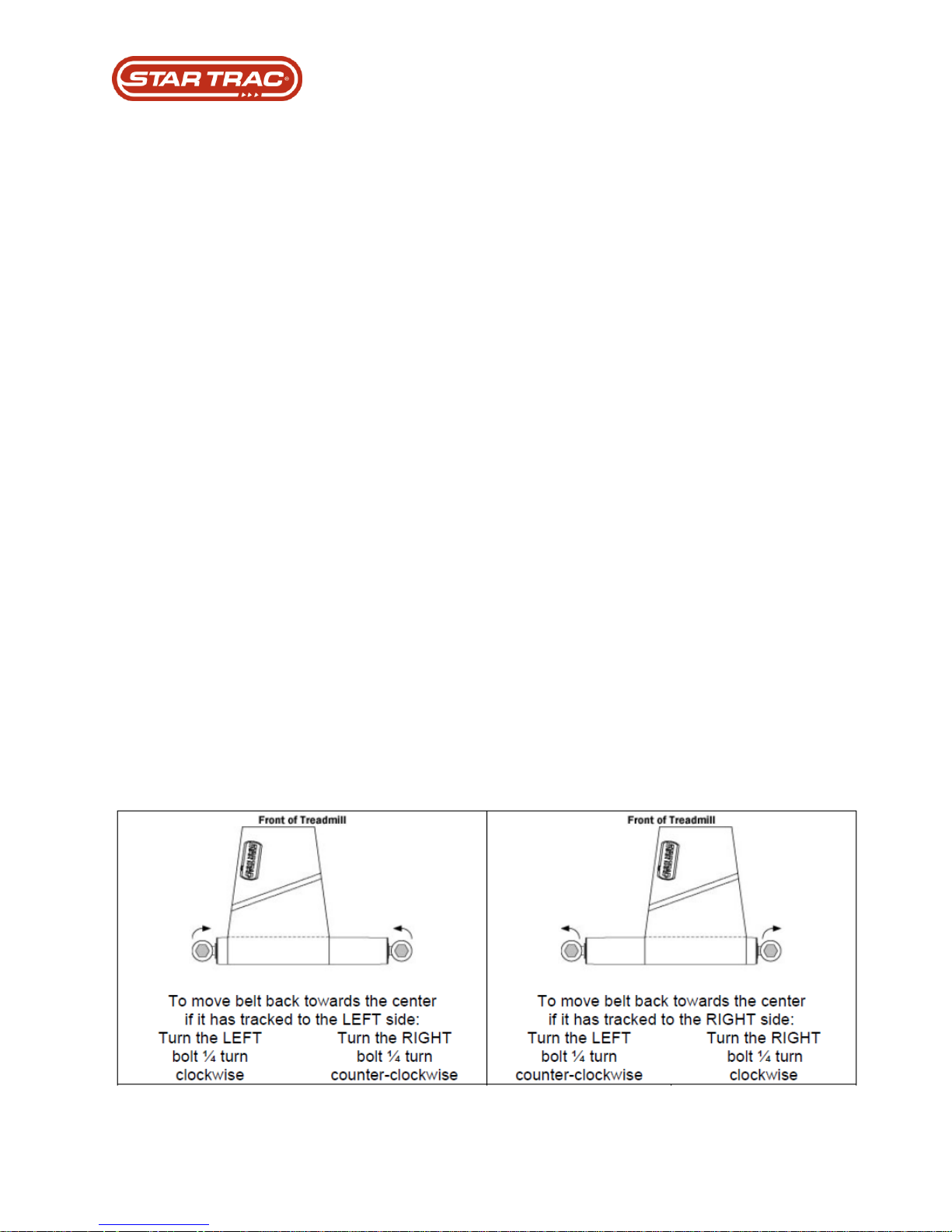
Belt Tracking:
If the running belt is not centered on the tailroller and is either too far left or right, adjust tracking
using the following steps:
1. Turn the treadmill on. Increase treadmill speed to 3.0 mph (5.0 kph).
2. Adjust tracking by turning the left Allen screws (located at the back sides of the tailroller)
with a 1/4" Allen wrench in 1/4-turn increments. If the running belt is tracking to the left,
turn the screws clock-wise in 1/4 turn increments. If the running belt is tracking to the
right, turn the left screw counter-clockwise in 1/4 turn increments.
3. NOTE: ONLY USE THE LEFT SCREW FOR TRACKING ADJUSTMENT.
4. After the running belt appears to be tracking properly, increase the treadmill speed to
10.0 mph (16.0 kph) and verify that the belt stays centered.
Stomp Test - Slipping-Running Belt:
Remove the motor shroud and operate the treadmill slowly at 1 to 2 mph (2 to 3 kph). While
observing the headroller, walk on the belt and try to slow it down by gently applying pressure
with your feet while holding the handrails. If only the running belt, and not the headroller, slows
down, tighten the running belt by turning both the right and left tailroller adjustment bolts clock
wise 1/4-turn. Repeat this adjustment until the running belt no longer slips; ensuring that you
turn both tailroller bolts an equal number of turns. Re-install the motor shroud. If the headroller
and the running belt both slow down, tighten the drive belt.
Last updated 03/06/2017 637-4504 Rev. B
Page 29

Part Replacement: Deck
Troubleshooting that must be done PRIOR to replacement:
1. DFR code 800
2. Confirm that the running belt logo ( STARTRAC ) is not 75% worn out
3. Confirm that the running belt is not over tension
4. Confirm that the running belt does not slip ( use stomp test )
5. Confirm that the running belt is aligned with the roller
6. Remove drive belt and check for roller noise
Versions / Changes:
1. Wax Removed From Decks
Adjustment requirements after replacement:
2. Required running belt installation
3. Required head roller replacement
Testing requirements after replacement:
1. Running belt tension and tracking
2. Running belt stomp test
Last updated 03/06/2017 637-4504 Rev. B
Page 30
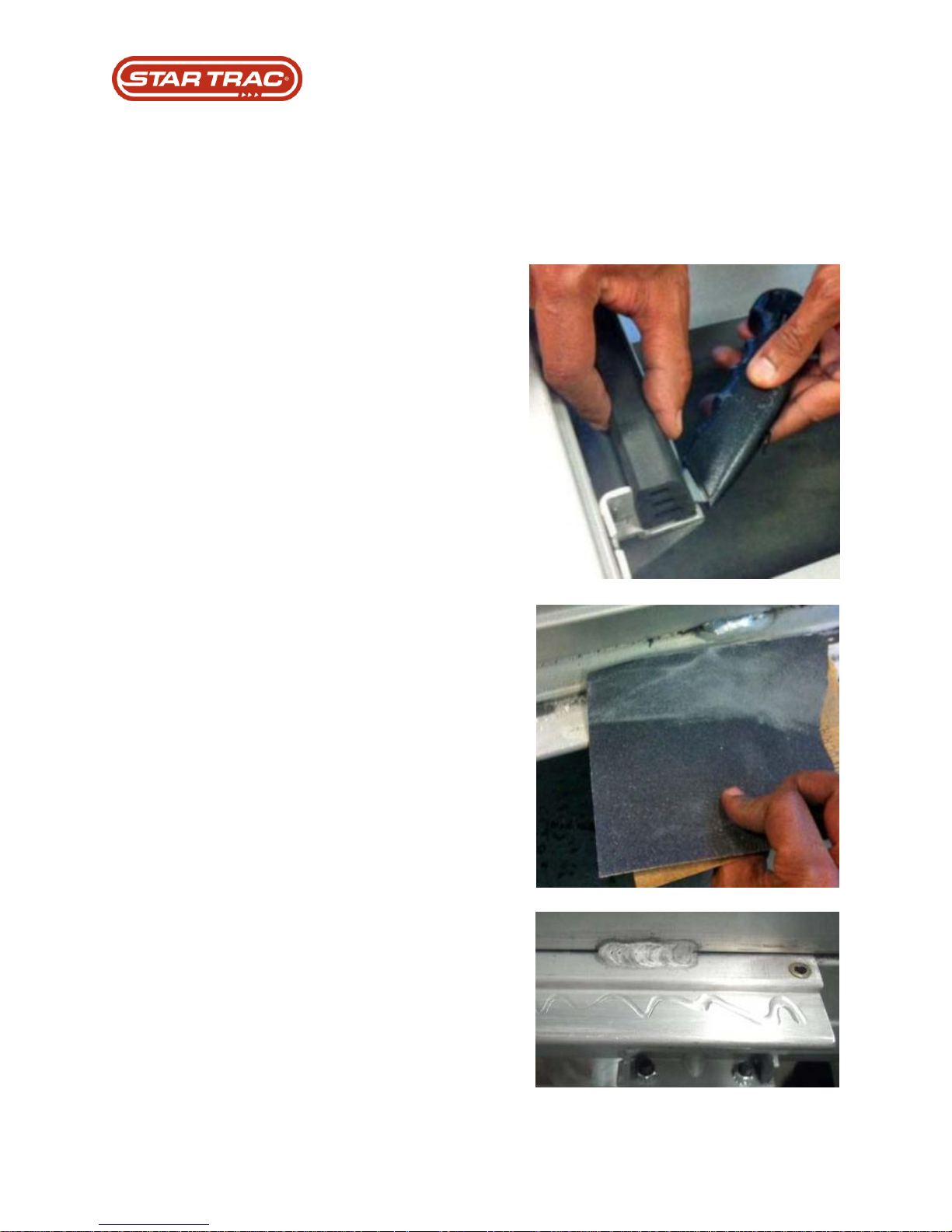
1. Remove running belt, deck, and
rollers.
2. Remove old deck cushioning
rubber. Use a putty knife or
scraping tool to remove all adhesive
residues from chassis.
3. After removing all the adhesive,
use180 grit sandpaper to remove
the remaining remnants and to
rough up the surface.
Note: Clean this area after
preparations are complete.
4. Apply epoxy in a zig zag pattern to
cleaned metal surface.
Part Replacement: Deck Cushion
Procedure:
Last updated 03/06/2017 637-4504 Rev. B
Page 31
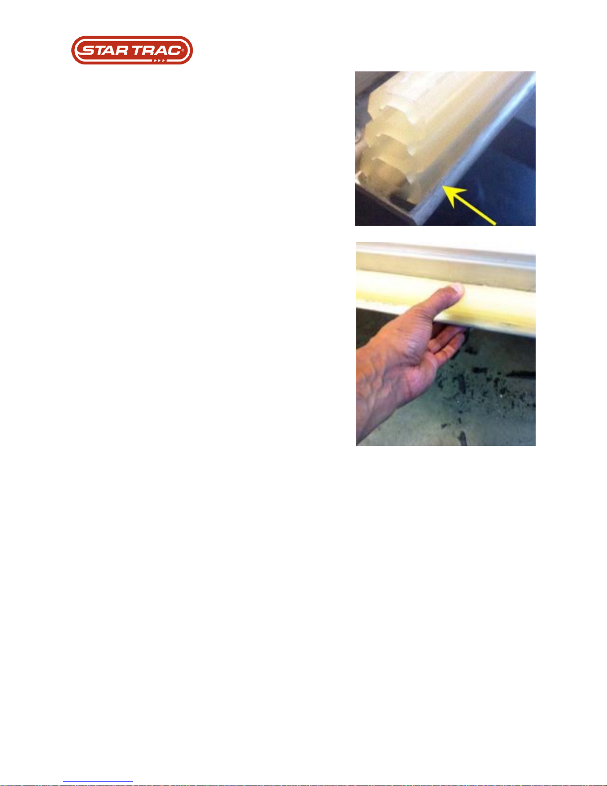
5. Lay the cushion on the frame with
the larger side on the bottom.
6. Align it and press down firmly on
various areas of the deck cushion for
30 seconds.
For best results, allow at least 15
minutes for the adhesive to cure before
putting the deck back on the frame.
7. Reinstall the rollers, belt, and deck
onto the frame.
Tip: Use a wet towel to moisten the top
of the rubber deck cushion before
installing the deck. This stop the deck
from sticking to the deck cushion when
being installed.
Last updated 03/06/2017 637-4504 Rev. B
Page 32

Part Replacement: Rollers
Troubleshooting that must be done PRIOR to replacement:
1. Confirm drive belt has right tension
2. Confirm drive belt is not worn
3. Confirm motor has not been adjusted
4. Remove drive belt from roller and check for roller noise
Versions / changes:
1. Treadmill Roller Crown Change Feb. 2008
Adjustments requirements after placing:
2. Confirm installation procedure
Testing requirements after placing:
3. Confirm drive belt has right tension
4. Confirm stomp test
The care and maintenance of the head and tail rollers are as important as the care and
maintenance of the running belt. Dirt buildup on the rollers can cause noise, rough feelings and
unwanted belt tracking.
Cleaning:
Scrape any dirt and debris build up from the roller using a plastic scraper or an old credit card.
Do not use anything metal or sandpaper, as you will damage the coating on the roller. Vacuum
up any debris from the rollers.
Roller “DO NOT’s”:
• Do not lubricate the roller bearings. They are a sealed type bearing and any lubricant you
attempt to apply, will not penetrate the seal.
• Do not scrape a roller with metal. Use a plastic scraper or a credit card only.
• Do not use sandpaper to clean the rollers
Last updated 03/06/2017 637-4504 Rev. B
Page 33

Part Replacement: EMI Filter
Troubleshooting that must be done PRIOR to replacement
1. Check for 120v AC input from wall.
2. Check for 120v AC out from power switch.
3. Check for 120v AC input to EMI filter.
4. Check for 120v AC output from EMI filter.
5. Check for 120v AC input to MCB.
Versions / Changes:
1. Last change was done in Feb/2008.
Programming requirements after replacement:
2. None required.
Testing requirements after replacement:
3. Perform a full function test on the machine.
Last updated 03/06/2017 637-4504 Rev. B
Page 34
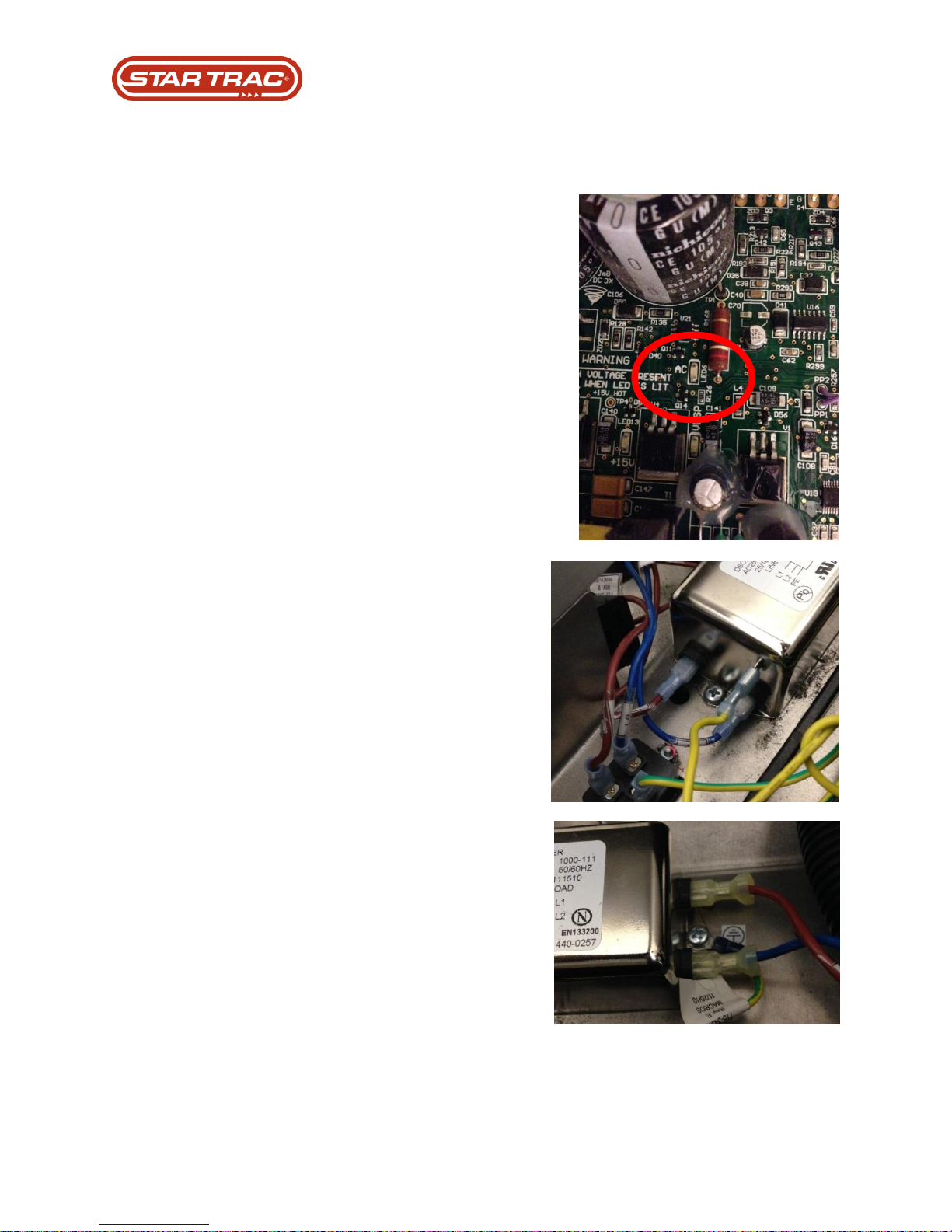
1. Turn unit off, unplug power cord from
the wall, and wait until AC LED on the
MCB has gone out.
1. Disconnect red and blue leads going
from the power switch/breaker into the
EMI filter and the red and blue leads
from the EMI filter out to the MCB
connector.
2. Disconnect the ground wire that
connects the EMI filter to the machine
chassis
3. Using a phillips head screwdriver,
loosen the two screws and disconnect
the EMI filter from the machine chassis.
4. Reverse Steps 1 – 3 for installation of
replacement EMI Filter.
Part Replacement: EMI Filter
Procedure:
Last updated 03/06/2017 637-4504 Rev. B
Page 35

Part Replacement
Part Replacement: MCB
Troubleshooting that must be done PRIOR to replacement
1. Check for voltage input to unit.
2. Check AC LED and V-CON LED’s are on.
3. Verify voltage into the EMI filter is 120v AC.
4. Verify 120v AC voltage out of the EMI filter input cable.
5. Verify that the fuse is good on the MCB.
6. Determine if the power connectors have any burn or scorch marks on the MCB.
7. Reseat display (I/O) cable on the MCB & display electronics board
8. Check Display cable out of MCB connected
9. Check MCB LEDs 8 and 11 for status ready Blinking
10. Check that the MCB’s LED 8 for status ready blinking
11. Verify a motor bleeder test must have 19 to 20 mega ohms.
12. Check Last Error List for a DFR 4000 code on the display (LED console).
Versions / Changes:
1. Version 1 MCB’s were updated to Version 2 in Feb/2011.
Programming requirements after replacement:
2. None required.
Testing requirements after replacement:
3. Perform a motor / speed calibration test
Last updated 03/06/2017 637-4504 Rev. B
Page 36
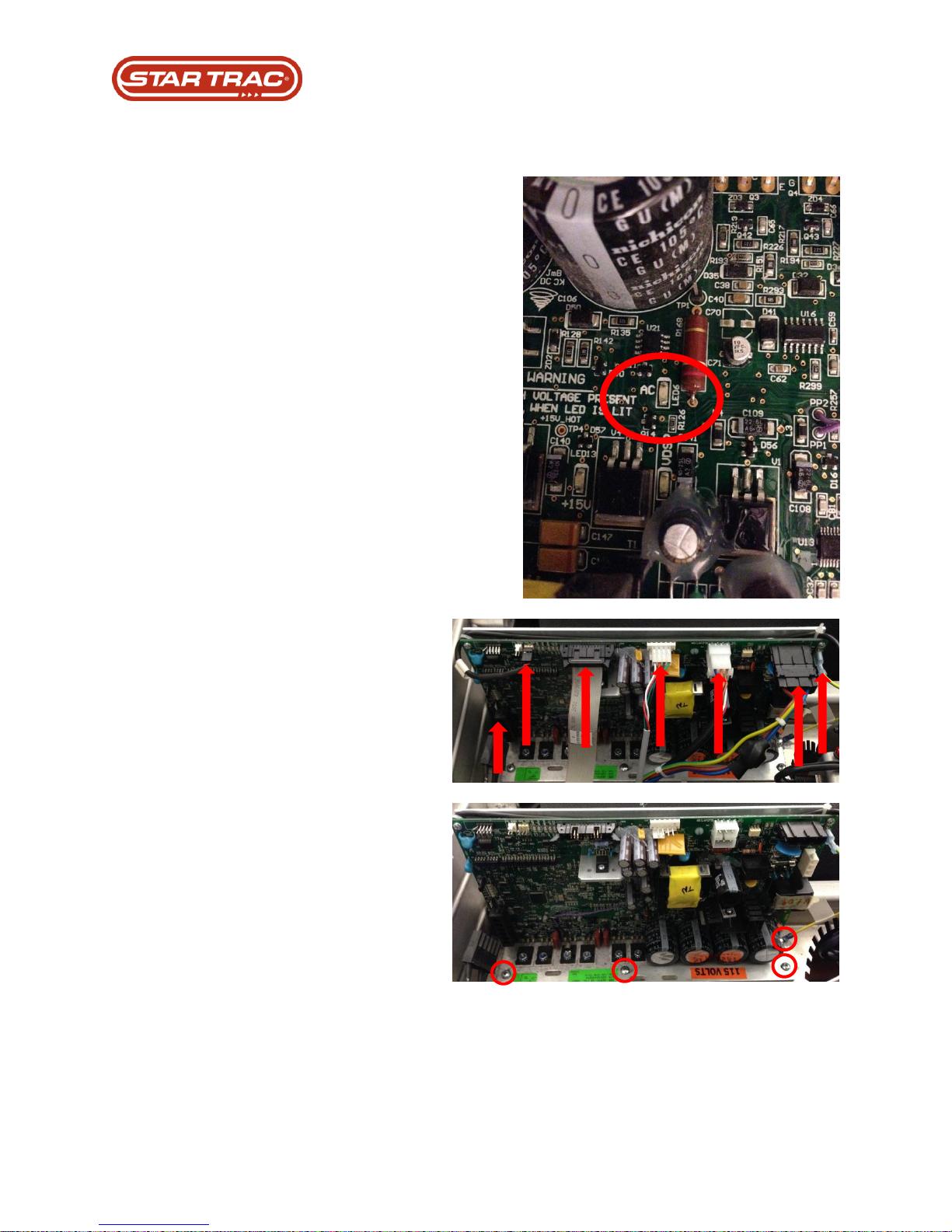
1. Turn unit off, unplug power cord
from the wall, and wait until AC
LED on the MCB has gone out.
2. Remove wiring connectors into
MCB for Motor, Speed Sensor, I/O,
12v DC power, Elevation, Power,
and Ground wire.
3. Remove 4 phillips head screws
that mount the board to the
chassis.
4. Reverse Steps 1 – 3 for installation
of replacement MCB.
Part Replacement: MCB
Procedure:
Last updated 03/06/2017 637-4504 Rev. B
Page 37
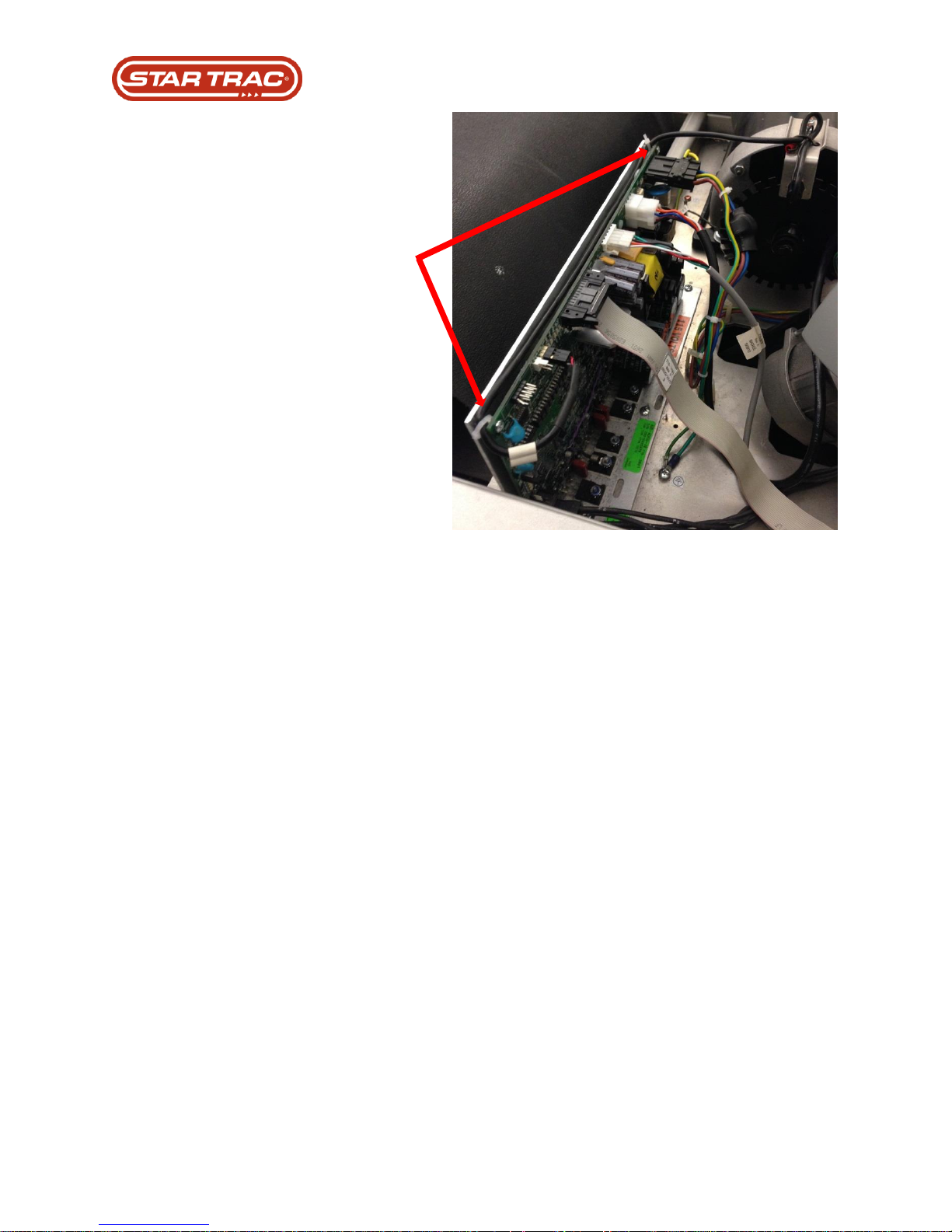
5. Ensure all wiring connectors are
seated fully into the MCB. Check
that wires are away from the RPM
disc of the motor and are routed
properly.
6. Make sure to re-route and zip tie
the speed sensor wire around the
back of the MCB.
Last updated 03/06/2017 637-4504 Rev. B
Page 38

Part Replacement: Drive Motor
Troubleshooting that must be done PRIOR to replacement
1. Check for DFR code 4000 in display
2. Check for voltage input to unit
3. Check AC led & V-CON LED’s on
4. Verify voltage in from the EMI is generating 120v AC
5. Verify that 120v AC voltage coming out from the EMI input cable
6. Perform a motor bleeder test must have 19 to 20 mega ohms.
7. Perform a continuity check on the thermostat wires from the motor
Versions / Changes:
1. Last change was done in Feb/2008
Programming requirements after replacement:
2. Perform a motor / speed calibration
Testing requirements after replacement:
3. Run program on unit
Last updated 03/06/2017 637-4504 Rev. B
Page 39
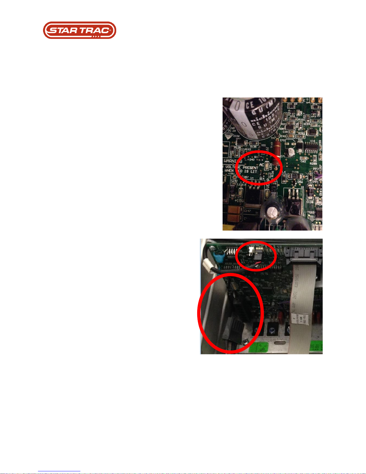
1. Remove the top motor shroud and
front bumper.
2. Turn unit off, unplug power cord
from the wall, and wait until AC
LED on the MCB has gone out.
3. Disconnect speed sensor and
remove zip ties holding it to the
MCB.
4. Disconnect motor wire harness
connector from the MCB.
Part Replacement: Drive Motor
Procedure:
Last updated 03/06/2017 637-4504 Rev. B
Page 40
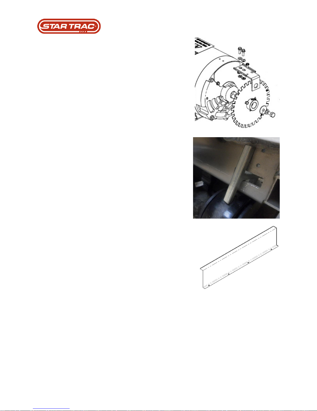
5. Remove the RPM sensor assembly
and the RPM disc from the motor.
Set aside for use on the
replacement motor.
6. Pull and turn the T-pin idler pulley
to remove tension on the drive belt.
Caution: pinch points.
7. Using a long phillips head
screwdriver remove the 4 screws
that hold the head roller finger
guard in place.
Last updated 03/06/2017 637-4504 Rev. B
Page 41
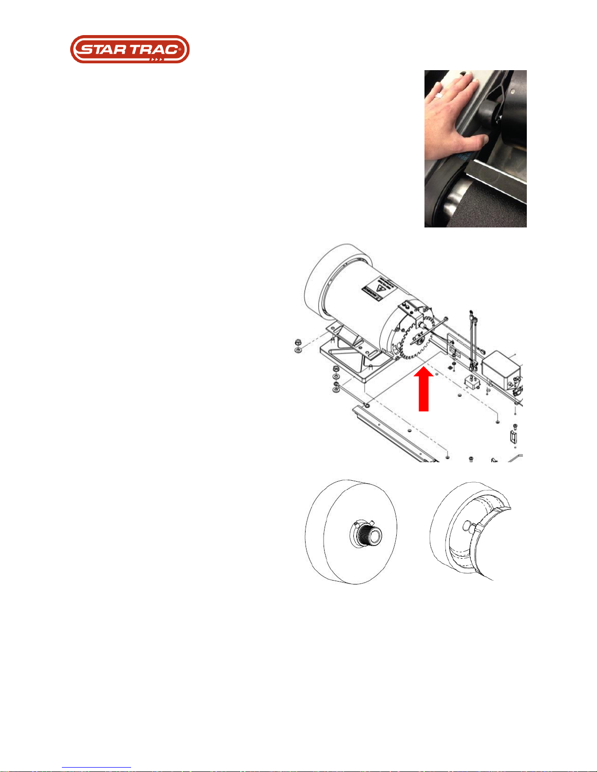
8. Walk the drive belt off of the
headroller pulley. Remove belt
from small pulley on motor.
9. Loosen the 4 bolts that connect the
motor to the chassis and remove
the motor and bleeder wire.
Lift motor up and take caution not
to damage the bolt threads.
Caution: the motor is heavy. Do
not to damage any of the bolt
threads, or wiring connections.
Leave the spacer block in place on
chassis of machine.
10. Loosen the two set screws that
connect the balance wheel to the
motor.
Using a rubber mallet, remove the
balance wheel from the shaft.
Remove the key from the motor
shaft slot.
11. Mount the key into the keyway and
the balance wheel onto the motor
shaft. Leave set screws snug, but
not tight. These will be adjusted to
properly align the motor and head
roller pulleys.
Last updated 03/06/2017 637-4504 Rev. B
Page 42
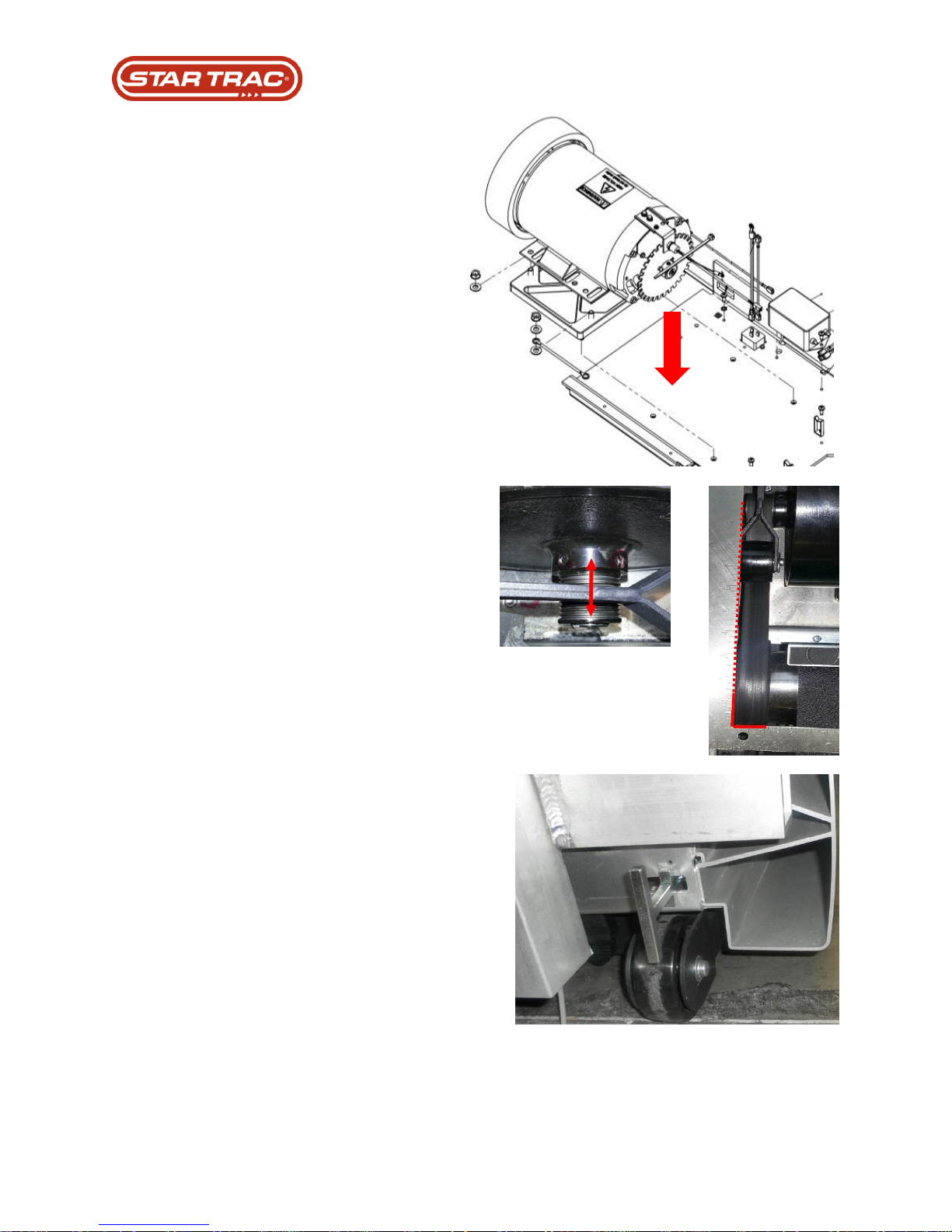
12. Place the replacement motor into
the chassis of the machine;
connect with 4 bolts, including
bleeder wire.
13. Using a straight edge, align
balance wheel with the head roller
pulley, apply blue Loctite to the set
screws, and tighten.
14. Walk drive belt back onto motor
pulley first and then the head roller
pulley.
Pull T-pin idler handle to re-tension
drive belt.
Last updated 03/06/2017 637-4504 Rev. B
Page 43
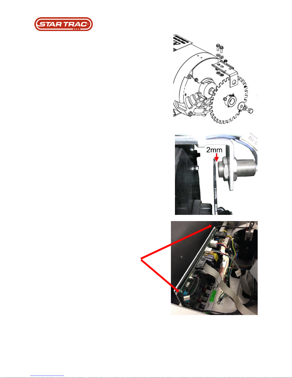
15. Mount the RPM disc to the motor
shaft using blue Loctite on the set
screws.
Torque set screws and shaft bolt to
60 – 66 Lb-In.
16. Mount the RPM sensor assembly
and ensure appropriate gaping
(2mm) of speed sensor and RPM
disc.
Adjust as necessary to ensure
proper gap.
17. Re-route the speed sensor wire
along the back of the MCB and zip
tie into place.
Plug the cable harness into the
corresponding MCB connector.
Last updated 03/06/2017 637-4504 Rev. B
Page 44
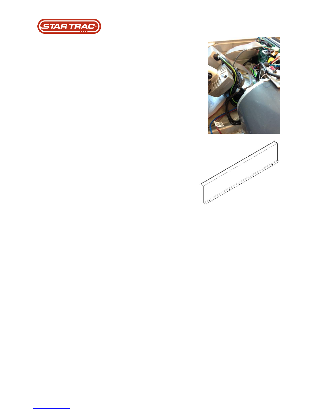
18. Re-route the new motor power
cable under and behind, or zip tied
to the front (as shown) of the
elevation motor and plug into MCB.
19. Reconnect dust cover / finger
guard.
20. Turn machine on and perform a
Speed / Motor Calibration in the
Maintenance Mode of the console.
21. Replace all machine shrouds.
Last updated 03/06/2017 637-4504 Rev. B
Page 45
Model
Incline Range
Min (zero elevation)
Max (full elevation)
E-TRx
0% - 20%
230
38
E-TR
0% - 15%
230
70
S-TRc
0% - 15%
235 - 230
67 – 75
S-TRx
0% - 15%
235 - 230
67 – 75
Model
Incline Range
Min (zero elevation)
Max (full elevation)
E-TRx / 8-TRx
0% - 20%
228
11
E-TR / 8-TR
0% - 15%
228
55
Part Replacement: Elevation Motor
Troubleshooting that must be done PRIOR to replacement
1. Check elevation settings on display are set within ranges listed below.
2. Check for elevation errors
3. Check elevation motor wires orange and blue to MCB with meter. 0% elevation reading
should be 9.4 -9.5 k ohms max elevation readings 500-600 k ohms.
4. Press up and down on incline check up /down LEDs on MCB
5. Check for AC output to elevation motor while elevating up or down on display volt meter
reading from 100v AC to 200v AC on RED and BLACK wires
6. E-series elevation motor check potentiometer in the elevation motor measure wires ohm
reading should be range 9.4 -9.5 k ohms at 0% ohm readings should range from 500 –
600 ohms at max elevation
7. Check display cable for any damage
Versions / Changes:
1. Last change was done in Dec. 2016. This change introduced 1.05 Display software, for
8-Series LCD displays, and 1.6 Translator Board software, for E and 8-Series 15”
Please note that this new version changed the elevation parameters as outlined
below:
Programming requirements after replacement:
2. Perform an elevation / incline calibration
OLD (pre V1.05) Calibration Values:
NEW (post V1.05) Calibration Values:
Testing requirements after replacement:
3. Run program on unit.
Last updated 03/06/2017 637-4504 Rev. B
Page 46
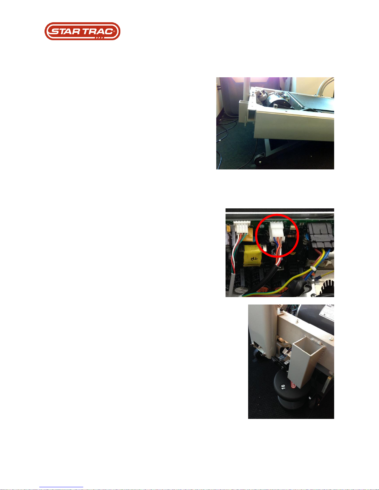
1. If possible, before replacing the elevation
motor, elevate treadmill.
2. Turn Power Off / Unplug from wall
3. Remove the shrouds (both top and front
bumper shown in Step 1).
4. Disconnect Elevation Motor wiring harness
from MCB and remove ground wire from
chassis.
Cut any zip ties on the elevation motor, or
elevation motor wire harness and remove it
from any cable stays on the machine
chassis.
5. With a partner, lift front end of machine and
place a dumbbell, jack stand, or 12” – 18”
4x4 on metal plate of the machine chassis
under power switch/power cable inlet.
Or, if space allows, turn the treadmill on its
user-left side.
Part Replacement: Elevation Motor
Procedure:
Last updated 03/06/2017 637-4504 Rev. B
Page 47
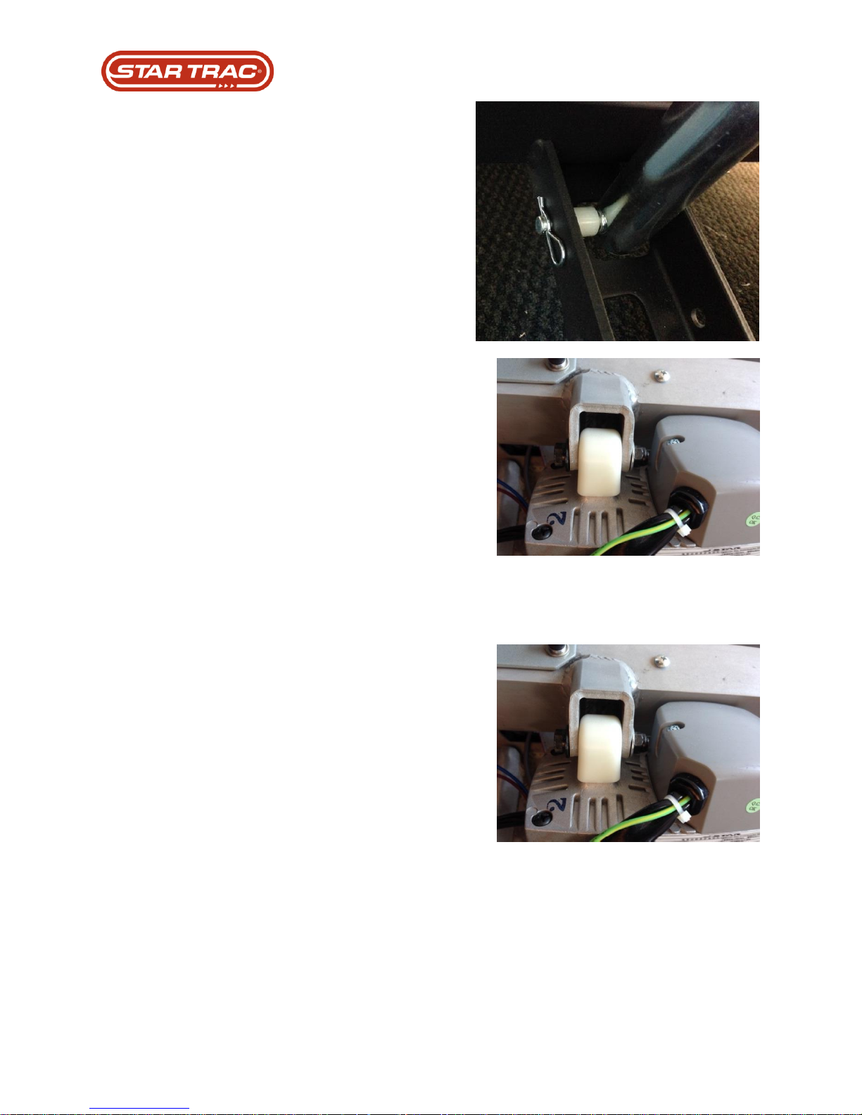
6. On the under-side of the machine, remove
cotter pin, pin, and spacer that connect the
motor to the lift bar of the machine.
Caution: potential pinch points when the
elevation frame weldment (lift bar) is
removed from the elevation motor.
7. Disconnect elevation motor from chassis and
retain plastic cover/grommet for use in the
replacement.
8. Remove old elevation motor. Take caution
not to damage any of the wiring harnesses
upon removal.
9. Install replacement elevation motor onto the
chassis making sure the lift screw is all the
way in (do this manually by turning).
Last updated 03/06/2017 637-4504 Rev. B
Page 48
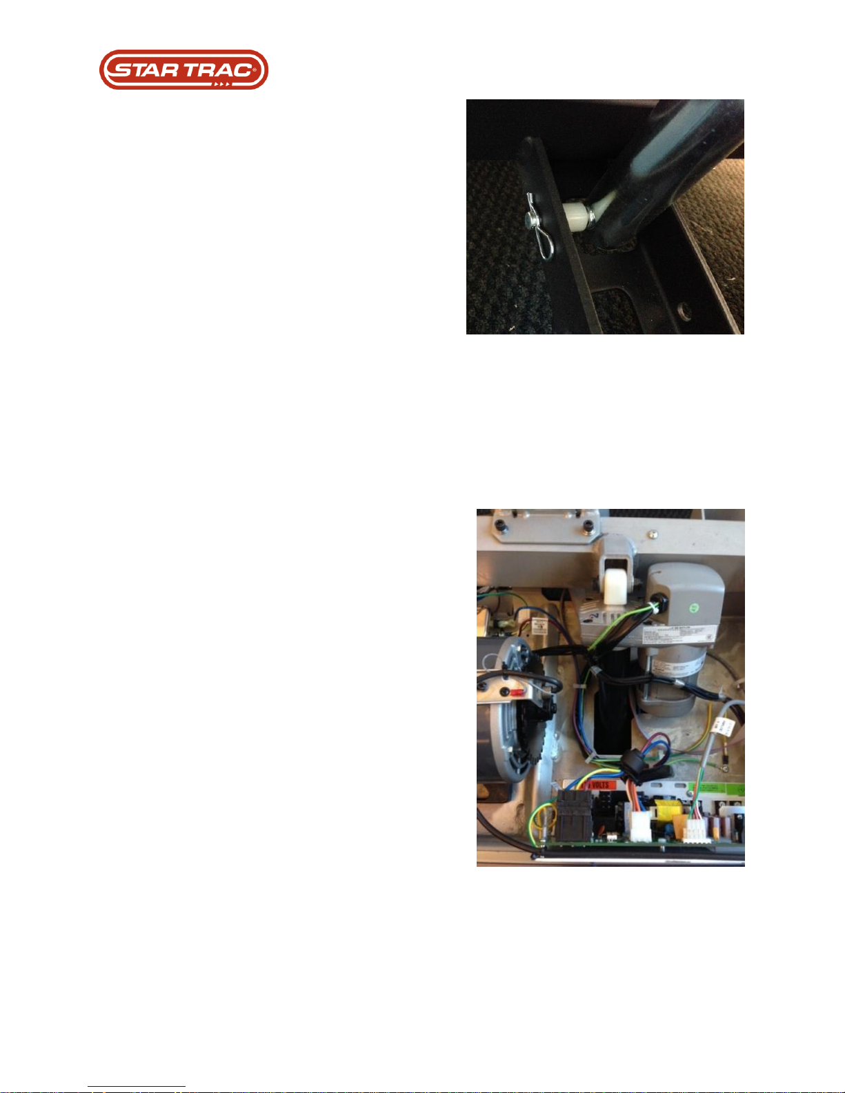
10. Align lift bar with pin with the elevation shaft
connector and insert pin, spacer and
connect. Don’t forget spacer.
11. With a helper, remove the jack, or 4x4
holding the unit up and return unit to the
ground.
12. Using a level ensure treadmill is level and
adjust leveling feet as needed. Use as the
base when running an elevation calibration.
13. Route Elevation motor wires away from the
RPM disc of the Drive motor. Connect wiring
harness to MCB connection and seat fully.
Ensure ground wire from Elevation motor to
machine chassis is connected.
Last updated 03/06/2017 637-4504 Rev. B
Page 49
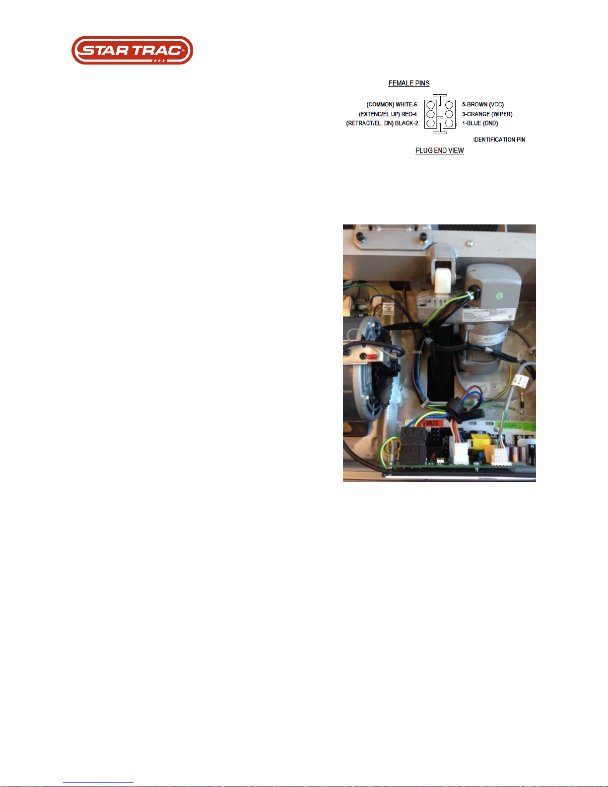
14. Verify potentiometer reading is 9.4 – 9.6
Ohms, blue and orange wire of elevation
MCB connector, when the treadmill is at zero
elevation.
15. Plug unit in, power on and perform an
elevation / incline calibration in the
Maintenance Mode of the console.
16. Re-zip tie elevation motor wiring to machine
chassis and reconnect shrouds.
Last updated 03/06/2017 637-4504 Rev. B
Page 50

Part Replacement: LED Display
Troubleshooting that must be done PRIOR to replacement
1. Check for DFR code on MCB
2. Check for EE error
3. Check AC led on MCB
4. Check V-CON led on MCB
5. Verify voltage input to MCB 120 volts AC from EMI
6. Verify the display (I/O) cable is connected from MCB to Display.
7. Check for damage on the display cable
8. Check voltage across C79 and ground 12 volts DC
Versions / Changes:
1. Last change was done in Feb/2008
Programming requirements after replacement:
2. Set appropriate machine maintenance mode, verify all other settings
3. Perform motor calibration
4. Perform elevation calibration
Testing requirements after replacement:
1. Perform a keypad test
2. Perform HR test
Last updated 03/06/2017 637-4504 Rev. B
Page 51
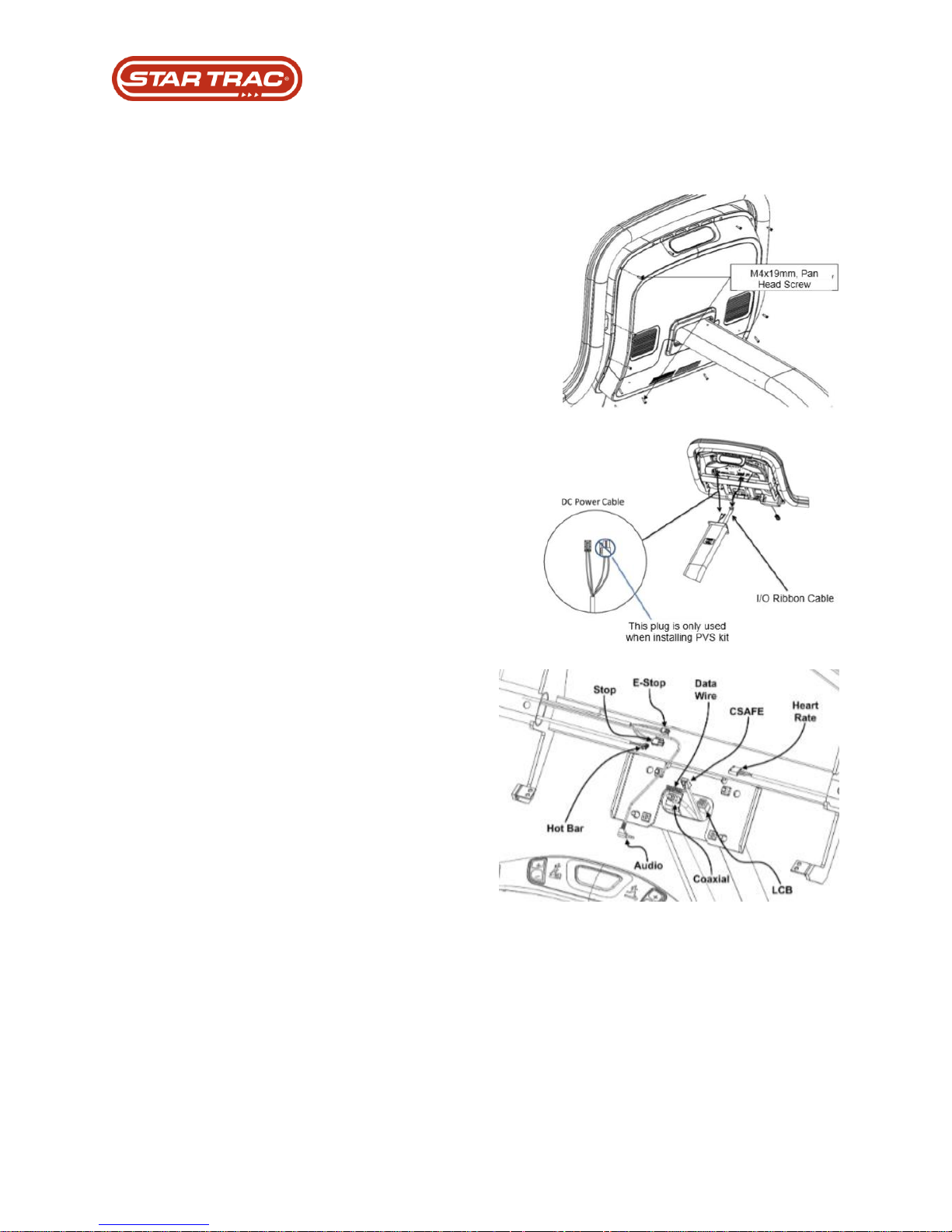
1. Using a phillips head screwdriver
disconnect upper and lower rear
covers from the console.
2. Disconnect the I/O Ribbon cable
and the DC Power Cable.
3. Remove all the applicable electrical
connections from the back of display
electronics board.
Part Replacement: LED Display
Procedure:
Last updated 03/06/2017 637-4504 Rev. B
Page 52
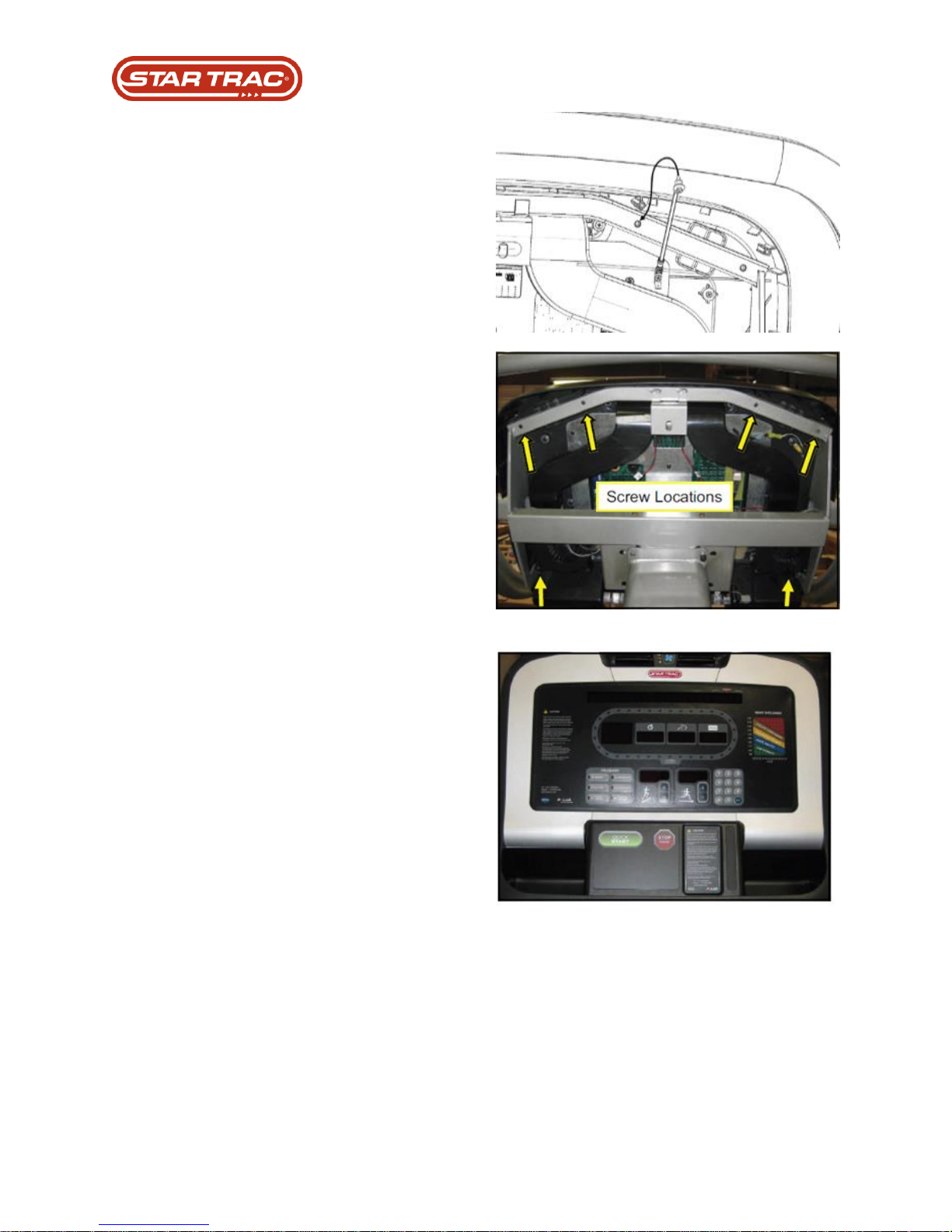
4. From the back of the display,
connect the grounding wire to the
frame using a washer & phillips
head screw.
5. Disconnect 6 screws that connect
the console to the machine chassis.
6. Prepare new display for mounting.
Last updated 03/06/2017 637-4504 Rev. B
Page 53
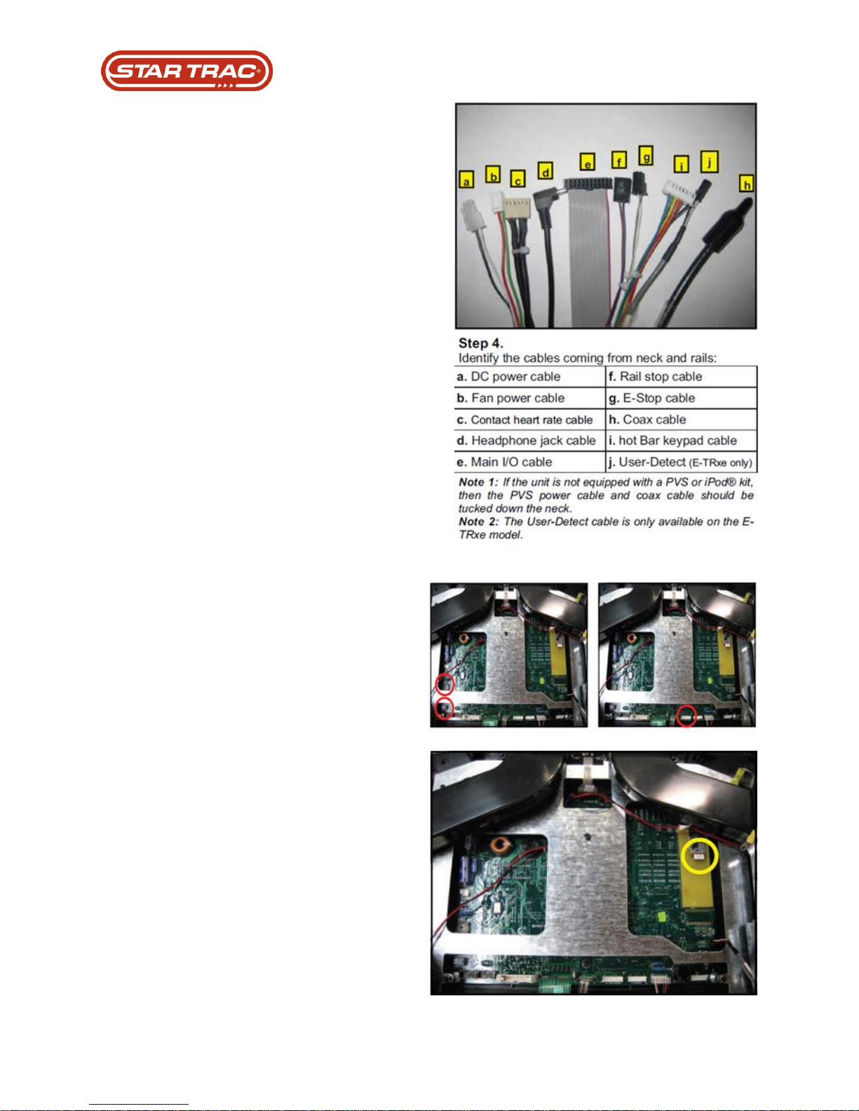
7. Identify all the applicable electrical
connections to the back of display
electronics board.
8. Connect the E-Stop cable (g) to the
J25 connector and connect the rail
stop cable (f) to the J5 connector on
the display board.
9. Connect the Hot Bar cable (i) to the
display board.
10. Connect the Contact Heart Rate
cable (c) to the display board.
Last updated 03/06/2017 637-4504 Rev. B
Page 54
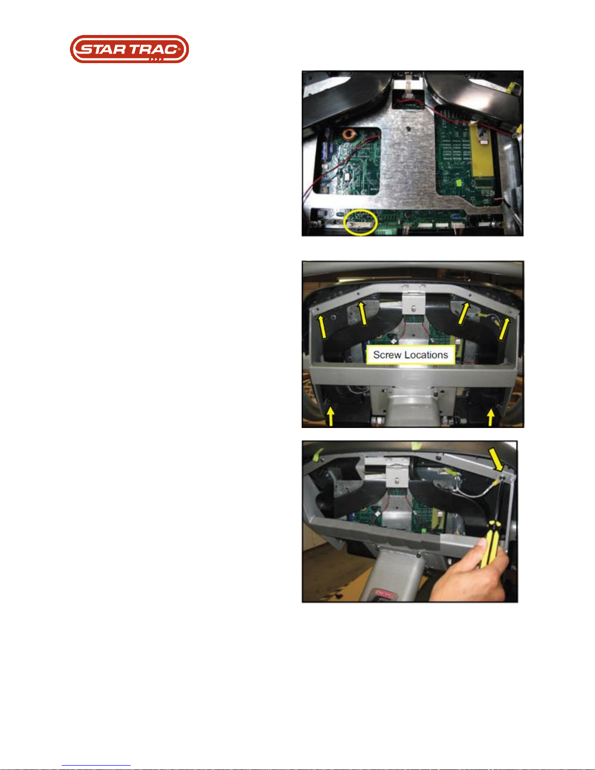
11. Connect the I/O ribbon cable (e) to
the display board and ensure it is
seated fully.
12. Reconnect new console to the
machine chassis.
13. Ensure ground wire is reattached.
14. Replace rear console covers. Turn
machine on and run Heart Rate and
Keypad Test procedures in
Maintenance Mode.
Last updated 03/06/2017 637-4504 Rev. B
Page 55

Part Replacement: LED Console Keypad / Display Electronics
Troubleshooting that must be done PRIOR to replacement:
1. Perform a keypad test
2. Check for ribbon cable damage
3. Check ribbon cable is connected to all pins on display board
Versions / Changes:
1. Last change was done in Feb/2008
Programming requirements after replacement:
2. None required
Testing requirements after replacement:
3. Perform a keypad test
Last updated 03/06/2017 637-4504 Rev. B
Page 56
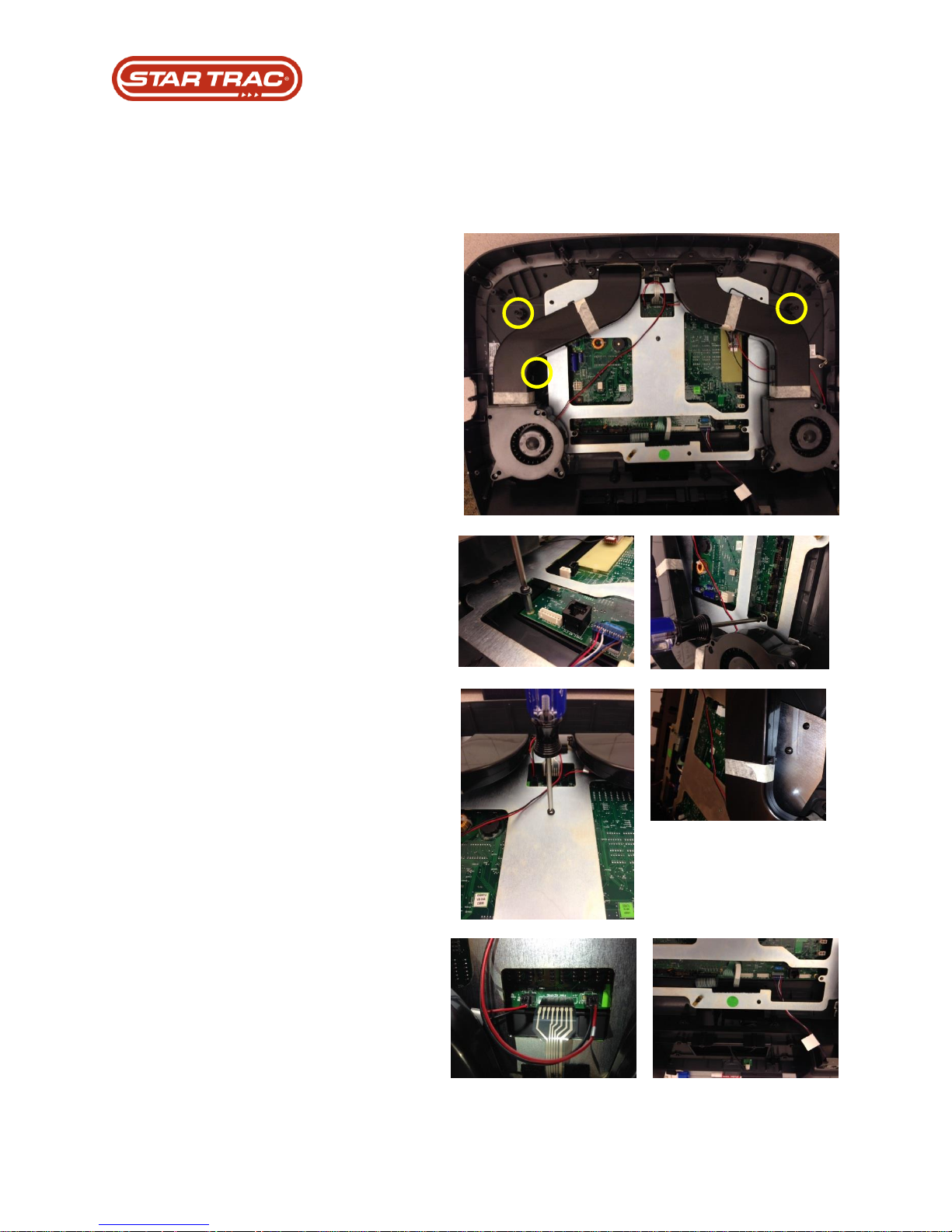
1. Remove console from chassis.
2. Disconnect 3 screws that connect
the overlay to the plastic console
housing.
3. Remove 5 sheet metal screws that
hold the Display Electronics onto
the metal brace of the console
housing.
4. Disconnect fan keypad, personal
cooling fan wire harnesses,
CSAFE, and hot bar connections
to the Display Electronics.
Part Replacement: LED Console Keypad / Display Electronics
Procedure:
Last updated 03/06/2017 637-4504 Rev. B
Page 57
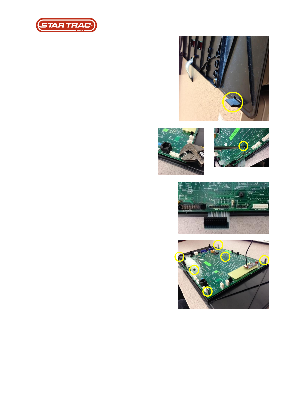
5. Remove the overlay and Display
Electronics from the plastic
console housing, making sure to
unhook the 2 clips at the base of
the keypad overlay.
6. Remove the keypad overlay from
the Display Electronics by
removing the 5 extension posts
and screw.
7. Disconnect main keypad ribbon
cable.
8. Fasten new keypad overlay to the
Display Electronics with the 5 post
extensions and screw.
Last updated 03/06/2017 637-4504 Rev. B
Page 58
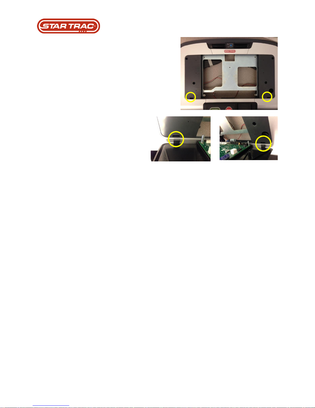
9. Reconnect the keypad overlay and
Display Electronics to the console
housing.
Note: ensure to align tabs at base
of keypad to the corresponding
holes in the console housing.
10. Reconnect wires back onto the
Display Electronics.
11. Remount console onto chassis.
Last updated 03/06/2017 637-4504 Rev. B
Page 59

Dates Sold
Software
Details / Differences
1st Generation
2008 - 2010
GUI 1.XX - 2.27
Either has no USB port for coaching stick or
the coaching USB port is on the mother
board.
TV Tuner mounted to motherboard of CPU.
2nd Generation
2010 - 2014
GUI 3.XX – 4.XX
The coaching port is a cable that sticks out
and the tuner card is mounting on the
mother board (ref doc 637-1422).
TV Tuner mounted to motherboard of CPU.
3rd Generation
2014 - Present
GUI 5.XX
External USB TV Tuner card mounted
outside the CPU sheet metal.
Part Replacement – Embedded Display
Troubleshooting that must be done PRIOR to replacement
1. Confirm power from FCB or MCB ver2 12v DC to CPU
2. Confirm power from the CPU 12v DC to CCB input
3. Confirm Power from Translator to FITCPU 12v DC
4. Confirm all setting and Model setting are correct
5. Confirm TV channel scan
6. Confirm touch screen calibration
7. Confirm software Version
8. Confirm touch screen error code
Versions / Changes:
Programming requirements after replacement:
1. Perform Motor calibration
2. Perform elevation calibration
3. Perform touch screen calibration
4. Perform channel scan
Testing requirements after replacement:
1. Verify all work out programs work
2. Verify that all channels are clear
3. Verify there is audio coming from the audio jack at the display housing
4. Verify that iPod menu/video will display on the screen
5. Verify touch screen response
Last updated 03/06/2017 637-4504 Rev. B
Page 60
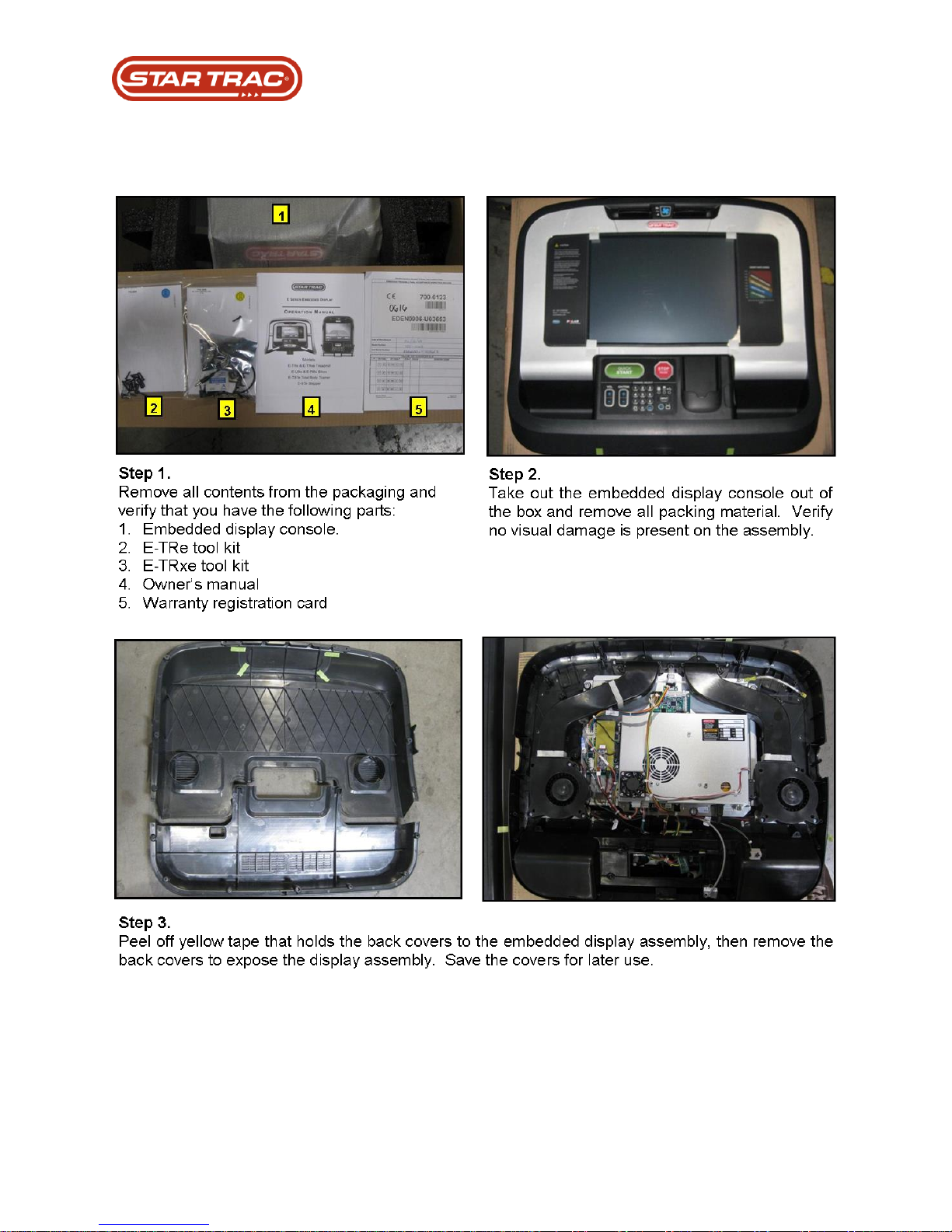
Part Replacement – Embedded Display
Procedure:
Last updated 03/06/2017 637-4504 Rev. B
Page 61
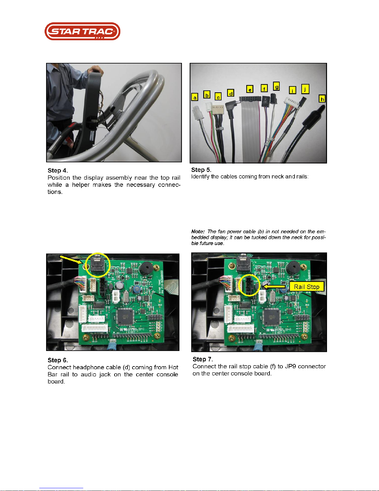
Part Replacement – Embedded Display
Last updated 03/06/2017 637-4504 Rev. B
Page 62
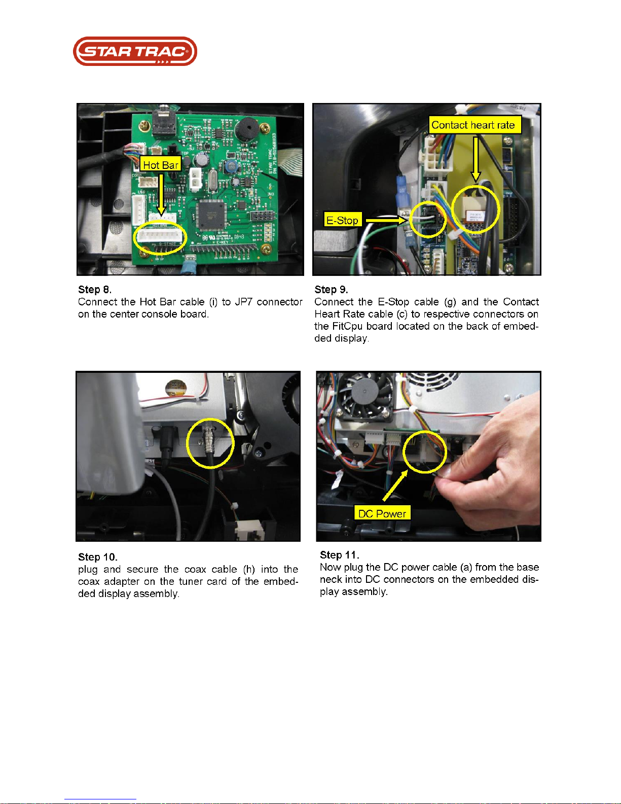
Part Replacement – Embedded Display
Last updated 03/06/2017 637-4504 Rev. B
Page 63
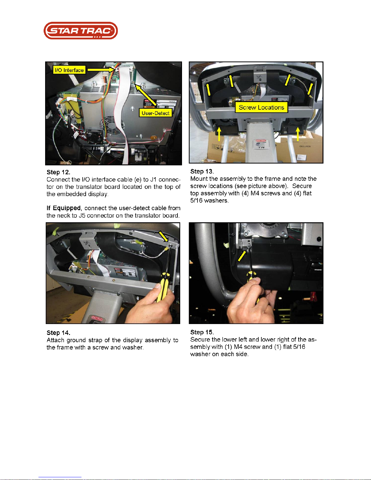
Part Replacement – Embedded Display
Last updated 03/06/2017 637-4504 Rev. B
Page 64
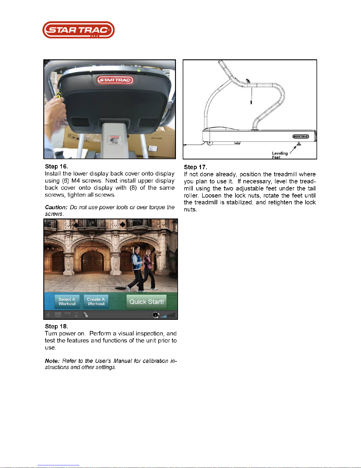
Part Replacement – Embedded Display
Last updated 03/06/2017 637-4504 Rev. B
Page 65

Part Replacement: CCB
Troubleshooting that must be done PRIOR to replacement:
1. Check CCB keypad for power lit LED (If no RED led is on follow CCB replacement # 22
2. Check the power for 12v DC input (under 11 volts DC replace power FCB or wire )
3. Check power input to PVS 12v DC. (Check for burn marks on cable/connectors)
4. Check for 12v DC output from CCB (if not found replace CCB board.)
5. Reseat all cable/plug connections.
6. Check all cable/plug connections for burn marks.
Version/Changes:
Programming requirements after replacement:
1. Perform channel scan
2. Delete any channels the facility does not want
Testing requirements after replacement:
1. Confirm iPod menu comes on
2. Confirm you can access the PVS programming mode
Last updated 03/06/2017 637-4504 Rev. B
Page 66
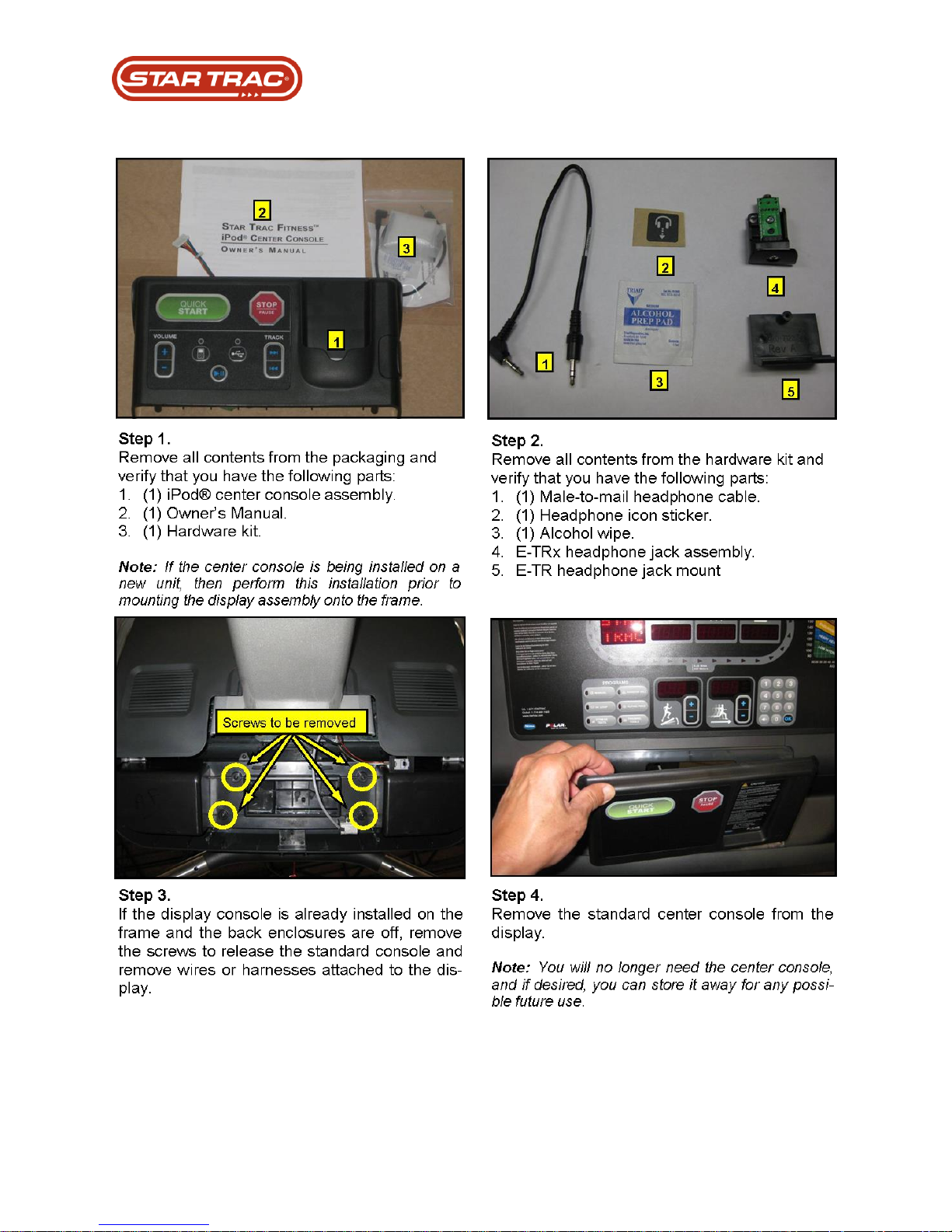
Part Replacement: CCB
Last updated 03/06/2017 637-4504 Rev. B
Page 67
Part Replacement: CCB
Last updated 03/06/2017 637-4504 Rev. B
Page 68
Part Replacement: CCB
Last updated 03/06/2017 637-4504 Rev. B
Page 69
Part Replacement: CCB
Last updated 03/06/2017 637-4504 Rev. B
Page 70
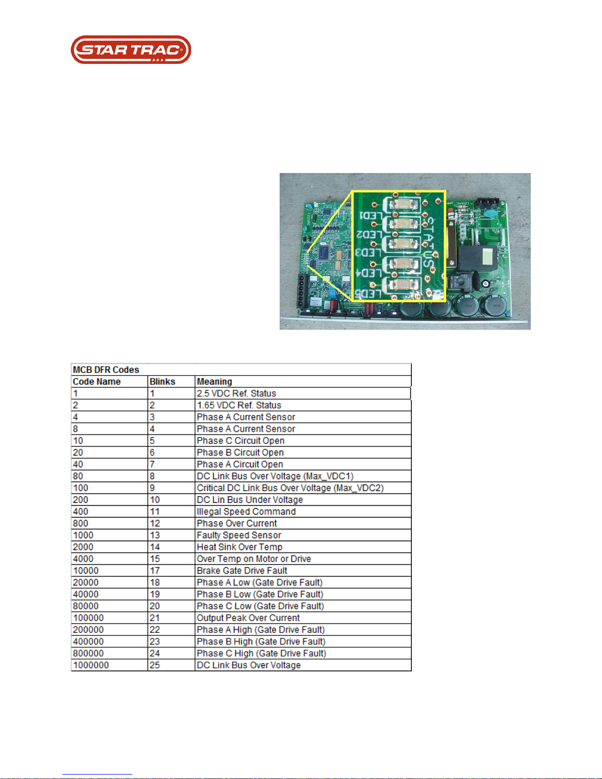
Under normal operation
circumstances, LEDs 1 – 3 blink in a
staggered pattern sequence.
When the machine is in an error
state, LEDs 1 – 3 blink together in a
repetitive pattern, pause, and then
blink in a repetitive pattern again.
The number of blinks can be counted
and their meaning can be referenced
in the flow charts below.
Troubleshooting
DFR Codes:
The MCB monitors various temperatures, currents and voltages coming in. When the
MCB senses an anomaly it will shut down and identify a Drive Fault Record (DRF) code.
Last updated 03/06/2017 637-4504 Rev. B
Page 71
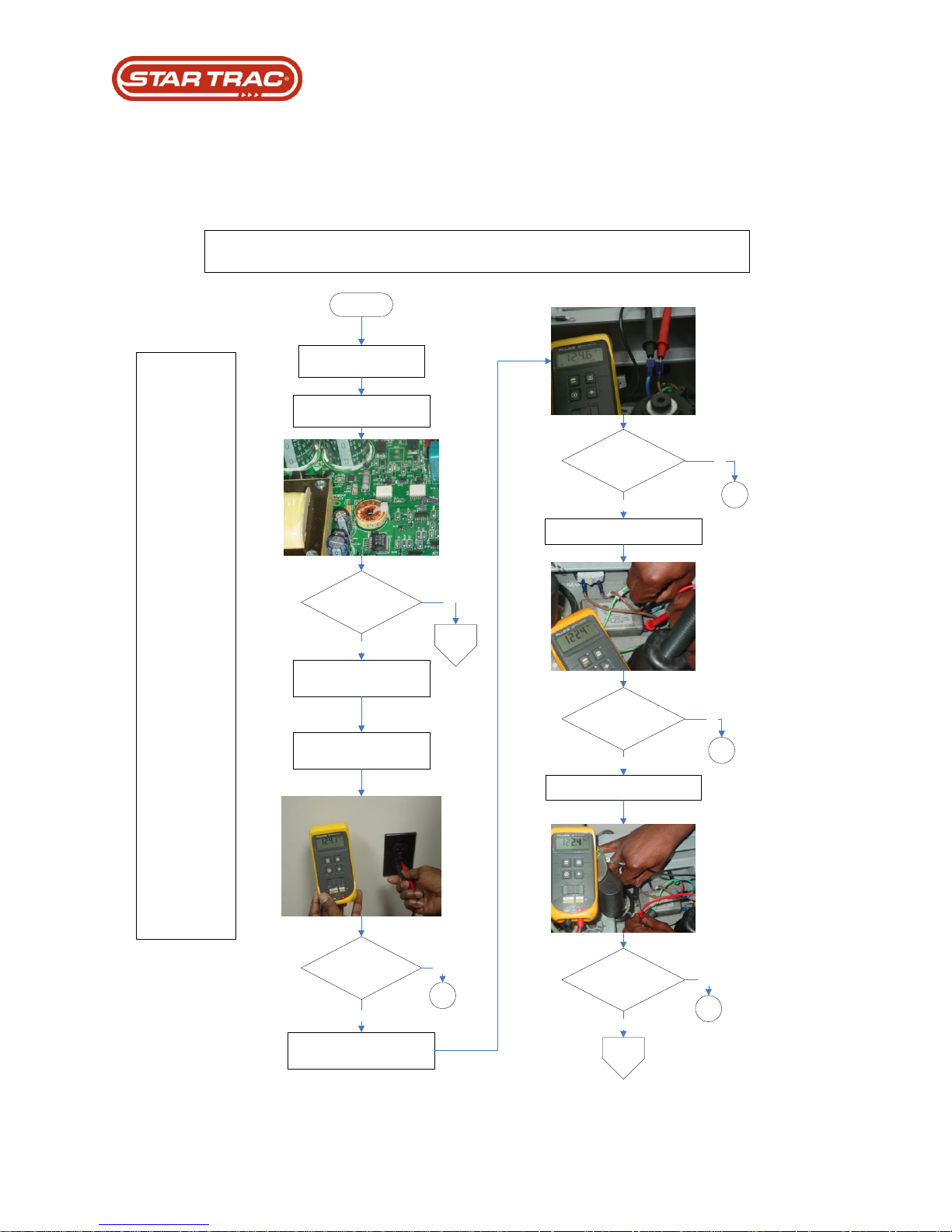
NO POWER TO DISPLAY
SOLUTIONS:
_________A1_______
Tripped Wall Breaker
or Bad Wall Circuit
_________A2_______
Replace Line Cord
_________A3_______
Replace On Off
Breaker
Note: Make sure the
line cord cables are
making a good
connection to the on
off breaker. Also make
sure the on off breaker
is turned to the of
position.
_________A4_______
Replace EMI Filter
Turn treadmill power on
Locate AC LED on the MCB
Is the AC LED off?
Verify all AC power wires are
making good connection
Yes
Measure wall output voltage
Measure EMI filter AC input voltage
Measure line cord output voltage
Was the wall output
voltage adequate?
Yes
Measure EMI output AC voltage
Was the
line cord output voltage
adequate?
A1
No
No
Yes
Was the
EMI filter input voltage
adequate?
Yes
A3
No
Was the
EMI filter output voltage
adequate?
A2
No
A4
No
Yes
Page 2
(A)
Start
Page 2
(B)
Troubleshooting
No Power to the Display
Last updated 03/06/2017 637-4504 Rev. B
Page 72
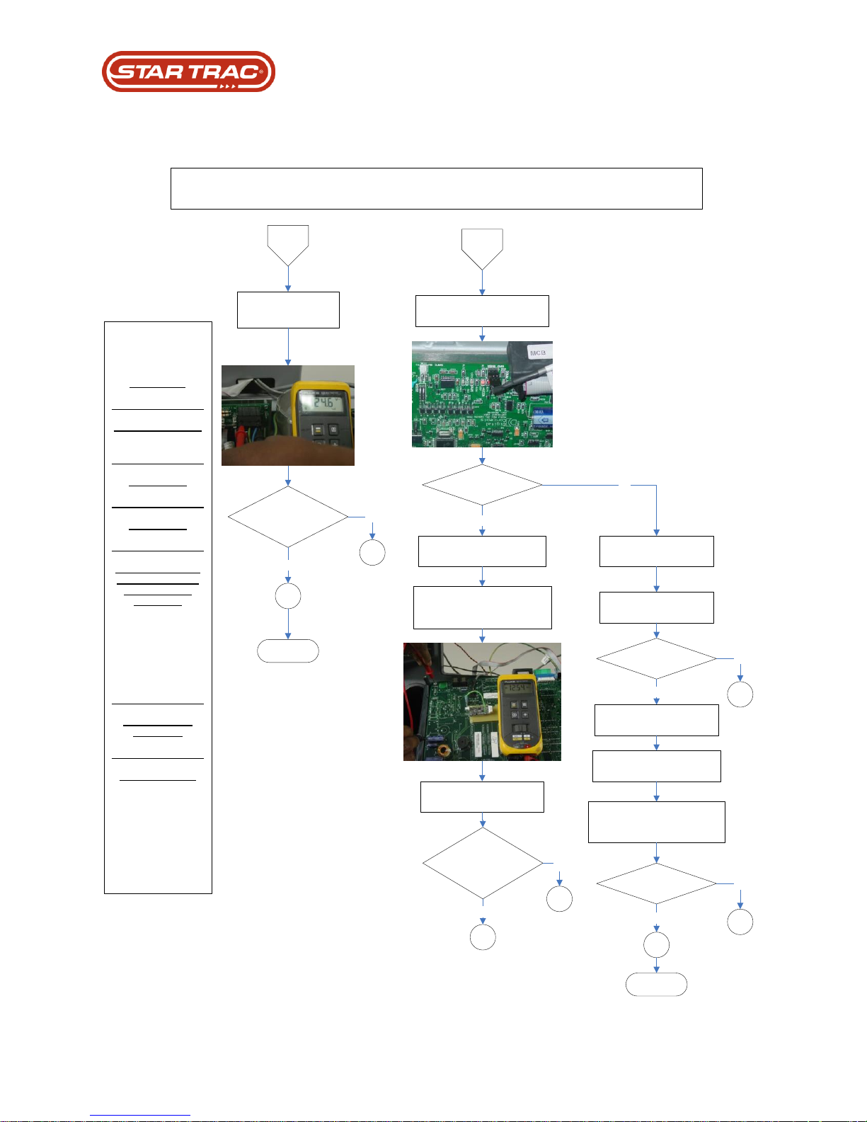
A
Measure MCB input
AC voltage
SOLUTIONS:
_________A5_______
AC MCB Input Cable
_________A2_______
Replace MCB
_________B1_______
Replace MCB
_________B2_______
Input component or
wire causing direct
short to display
electronics
Note: Plug one cable in
at a time into display
electronics to determine
the component or wire
that needs to be
replaced.
_________B3_______
Replace Display
Electronics
_________B4_______
Replace I/O Cable
Note: If problem still
exist after replacing the
I/O cable, replace display
electronics.
NO POWER TO DISPLAY
Was the
MCB input AC voltage
adequate?
A5
No
A6
Yes
B
Locate V-Con LED on the MCB
End
Is the
V-Con LED lit?
No
Unplug the I/O cable
(Display Cable)
Yes
Is the
V-Con LED lit?
Disassemble back display
housing
Again check V-Con LED
No
Yes
Measure display input DC
voltage across positive side of
C79 and display ground
Voltage should be
approximately 12 volts
Was the display input
DC voltage adequate?
B1
Open display panel to expose
display electronic
Leaving only the I/O cable
plugged in disassemble all other
wires from display electronics
Is the
V-Con LED lit?
Yes
B2
B3
No
End
Re-connect the I/O cable
Back into the MCB
B3
Yes
B4
No
No Power To The Display
Last updated 03/06/2017 637-4504 Rev. B
Page 73
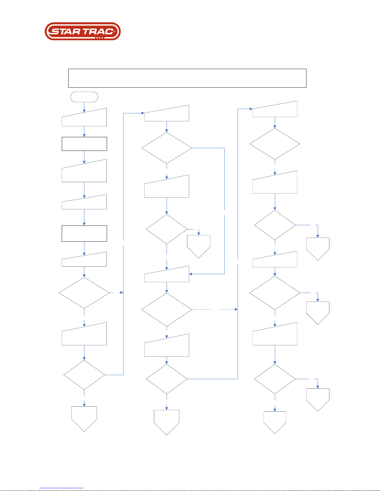
CHECK SPEED SYSTEM / CHECK MOTOR SYSTEM (AC MOTOR)
Start
Press 0, 2, and start
keys simultaneously
Screen will display
“Maintenance Mode”
Screen will display
“Press list error to view
last error list”
Press “Incline – or +“
key until display reads
“Last Error List”
Press “OK” key
Press “Speed – or +“
key until display reads
“Last DFR (5)xxxxxxxx”
Does
DFR (5) register
any # greater
that zero?
Yes
Press “5” key
Does the
Last Code (5) read
Check MO or
Check SP?
No
Yes
Does the
Last Code (4) read
Check MO or
Check SP?
No
Press “Speed – or +“
key until display reads
“Last DFR (4)xxxxxxxx”
Yes
Press # 4 key
Does
DFR (4) register
all zero?
Press # 3 key
No
Yes
Does the
Last Code (3) read
Check MO or
Check SP?
No
Press “Speed – or +“
key until display reads
“Last DFR (3)xxxxxxxx”
Yes
Does
DFR (3) register
any # greater
that zero?
Yes
Press # 2 key
No
No
Does the
Last Code (2) read
Check MO or
Check SP?
Press “Speed – or +“
key until display reads
“Last DFR (2)xxxxxxxx”
Yes
Does
DFR (2) register
all zero?
Press # 1 key
Yes
Does the
Last Code (1) read
Check MO or
Check SP?
No
Press “Speed – or +“
key until display reads
“Last DFR (1)xxxxxxxx”
Yes
Does
DFR (1) register
any # greater
that zero?
Call for
tech
support
Yes
No
No
Refer to
DFR #
flowchart
Refer to
DFR #
flowchart
Refer to
DFR #
flowchart
Refer to
DFR #
flowchart
Refer to
DFR #
flowchart
Refer to
DFR #
flowchart
Error Code - Check Speed Systems
Last updated 03/06/2017 637-4504 Rev. B
Page 74
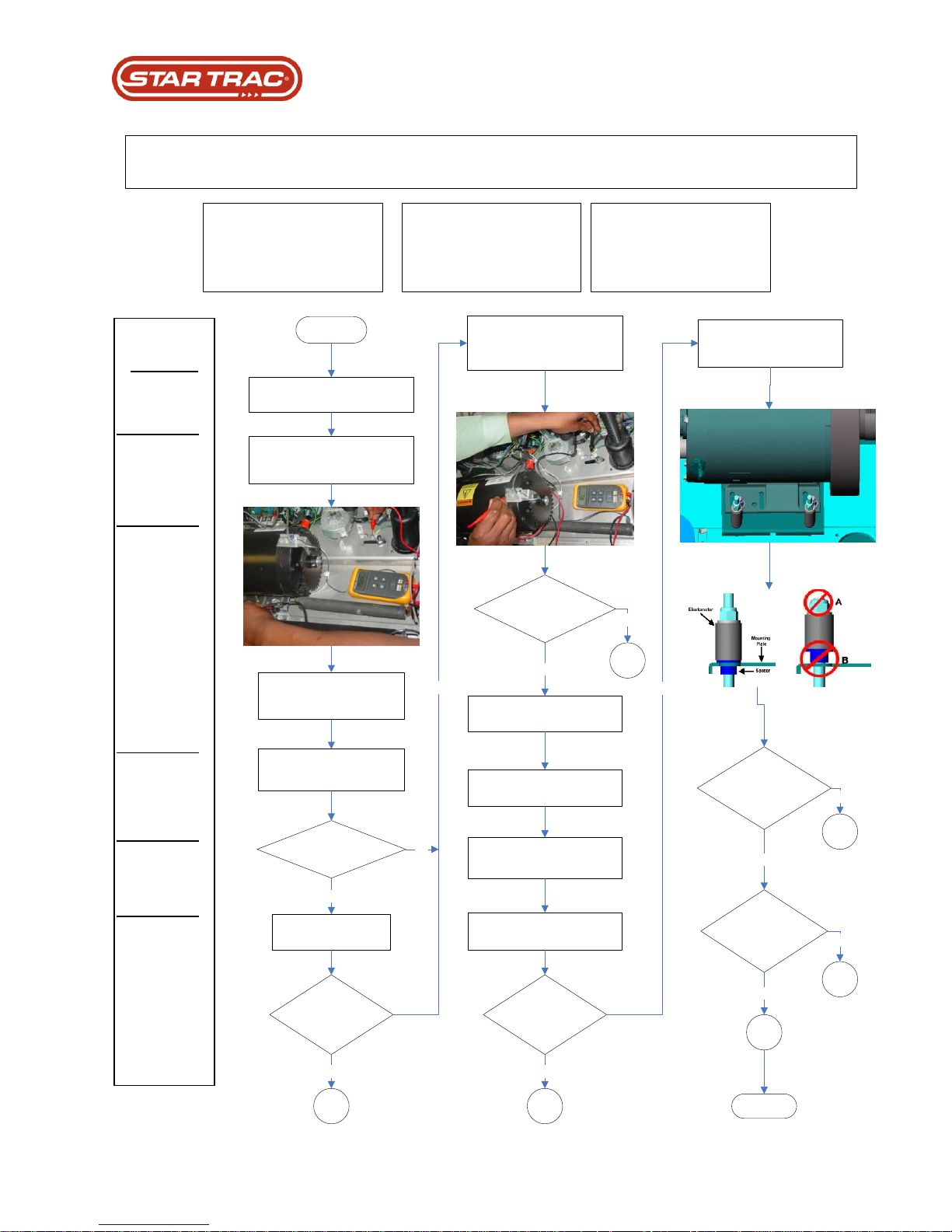
Turn the tread AC power off.
Measure ohms between TM
ground and drive motor bracket.
Measurement should read
approximately 19 mega ohms.
Did the
measurement read an
open circuit?
Yes
Start
Make sure multimeter ohm
setting is greater than 20
Mega ohms.
Measure ohms directly
on bleeder resistor.
Does the
Circuit measurement
read open?
B1
Yes
Measure continuity between TM
ground and drive motor sensor
bracket screw.
No
No
Measure ohms on brake
resistor
Does the
Circuit measurement
read closed?
Yes
B2
No
Disconnect brake resistor wires
from MCB
Make sure multimeter ohm
setting is greater than 1K ohms.
Does the
Circuit measurement
read open?
Measurement should read
approximately 19 mega ohms.
B3
Yes
First addition of AC drive
motor system had a floating
motor bracket
Does this
unit have the old style
motor bracket?
No
Are the
spacers mounted
properly into the
bracket?
Yes
B4
No
B5
Yes
B4
No
Solution:
B1____
Replace Bleeder
Resistor
B2____
Isolate drive motor
from ground.
Note: Check motor
bracket gaskets,
sensor bracket
gasket, or anything
else related that is
causing the drive
motor to have
continuity with
ground.
B3____
Replace brake
resistor
B4____
Replace MCB
B5____
Isolate bracket bolts
for the motor
bracket.
Note: Reattach
spacers through the
motor bracket and
re-tighten nuts.
End
DFR Code = 10000
Brake Gate Drive Fault / 17 Blink
Possible Causes:
(1) Faulty MCB.
(2) Bad or missing bleeder resister.
(3) Drive motor not isolated.
DFR Code = 100000
Output Peak Over Current / 21 Blink
Possible Causes:
(1) Bad or missing bleeder resister.
(2) Bad brake resister.
(3) Drive motor not isolated.
DFR Code = 1000000
DC Link Bus Over Voltage / 25 Blinks
Possible Causes:
(1) Faulty MCB.
(2) Bad or missing bleeder resister.
(3) Drive motor not isolated.
DFR CODE FLOWCHART: DEFINITIONS / MCB LED Blinks
DFR Flowchart For #: 1000000, 100000, and 10000
Last updated 03/06/2017 637-4504 Rev. B
Page 75
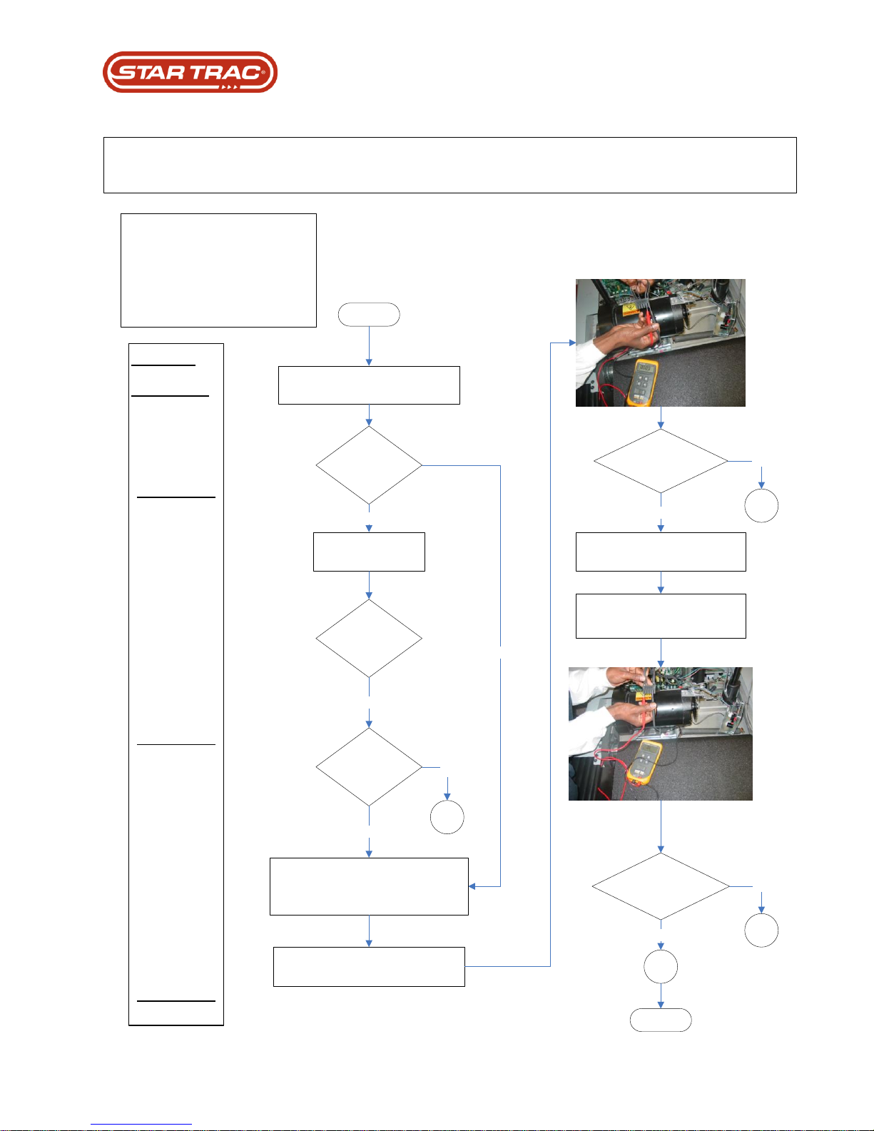
Solution:
C1____
If the unit came up
with check speed or
check motor system
refer back to the
correct DFR number
listed on A1.
C2____
Replace Drive
Motor
Note: Verify the
probes of the
multimeter are
making a good
connection with the
thermostat wires
labeled 5 and 6 on
honest connector.
Only take reference
to the drive motor
honest connector,
not the drive motor
wires they may not
coincide with each
other.
C3____
Replace Drive
Motor
Note: Verify the
probes of the
multimeter are
making a good
connection with the
thermostat wires
labeled 5 and 6 and
Phase wires labeled
1, 2, and 3 on
honest connector.
Only take reference
to the drive motor
honest connector,
not the drive motor
wires they may not
coincide with each
other.
C4____
Replace MCB
Start
Recycle the tread AC power by turning
it off and back on
Run TM belt by
pressing quick start key
Does the
running belt have
movement?
Did the
TM error out with
a 4000 DFR
code?
Yes
No
Yes
No
Does the
circuit measurement
read closed?
Yes
C2
No
Measure continuity on thermostat
and phase wire on drive motor
Plug one probe into any thermostat
wire (5 or 6) and the other probe into
any of the phase wires (1, 2 or 3)
Does the
circuit measurement
read open?
Yes
C3
No
Did the relay
switch on MCB
activate?
Yes
Measure continuity on drive motor
thermostat wires (pin 5 and 6)
Verify the drive motor, sensor, and display
cable wires are not damaged and making a
good connection with MCB.
C1
C4
End
DFR Code = 4000
Over Temp on Motor or Drive / 15 Blink
Possible Causes:
(1) Open thermostat wires on drive motor.
(2) Drive motor over heating.
(3) Faulty MCB.
DFR CODE FLOWCHART: DEFINITIONS / MCB LED Blinks
DFR Flowchart For #: 4000
Last updated 03/06/2017 637-4504 Rev. B
Page 76
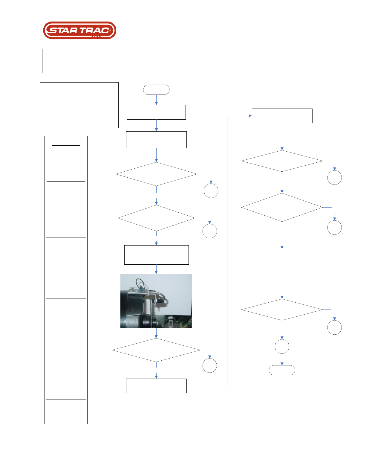
Solution:
__ D1_______
Replace Speed
Sensor
__ D2_______
Connect sensor wire
and retest
Note: Make sure
there’s no objects or
moveable parts that
may cause damage
to the wire.
__ D3________
Clean between
speed sensor and
disk to make sure
there is nothing
obstructing the
signal. Also make
sure the gap is
approximately 16th of
an inch difference.
__ D4________
Go back to last error
list and look for other
DFR codes different
than 1000
Note: Possible there
is another DFR in the
system due to sensor
failure will not cause
the unit not to run in
test mode.
__ D5________
Replace Speed
Sensor and if unit still
fails replace MCB
__ D6________
Unit is operable and
can be used again
Start
Turn the tread AC power off.
Check speed senor for
damaged or disconnected wire
Do the wire appear to
be in good condition?
Was the
Wire making a good connection
with the MCB?
Yes
D1
No
D2
No
Yes
D3
No
Was there
clearance and proper gaping between
the sensor and disk?
Yes
Engage motor test mode
Increase PWM to 100
Check for dirt build up between
the sensor and disk and proper
gaping.
Was there any belt movement?
Was there a sensor reading
in motor test mode
Yes
D4
D1
No
No
Calibrate running belt and retest
the unit in regular users mode
Yes
Does the 1000 DFR
code re-occur?
D6
D5
Yes
No
End
DFR Code = 1000
Faulty Speed Sensor / 13 Blinks
Possible Causes:
(1) Sensor disconnected.
(2) Faulty speed sensor.
(3) Faulty MCB.
DFR CODE FLOWCHART: DEFINITIONS / MCB LED Blinks
DFR Flowchart For #: 1000
Last updated 03/06/2017 637-4504 Rev. B
Page 77
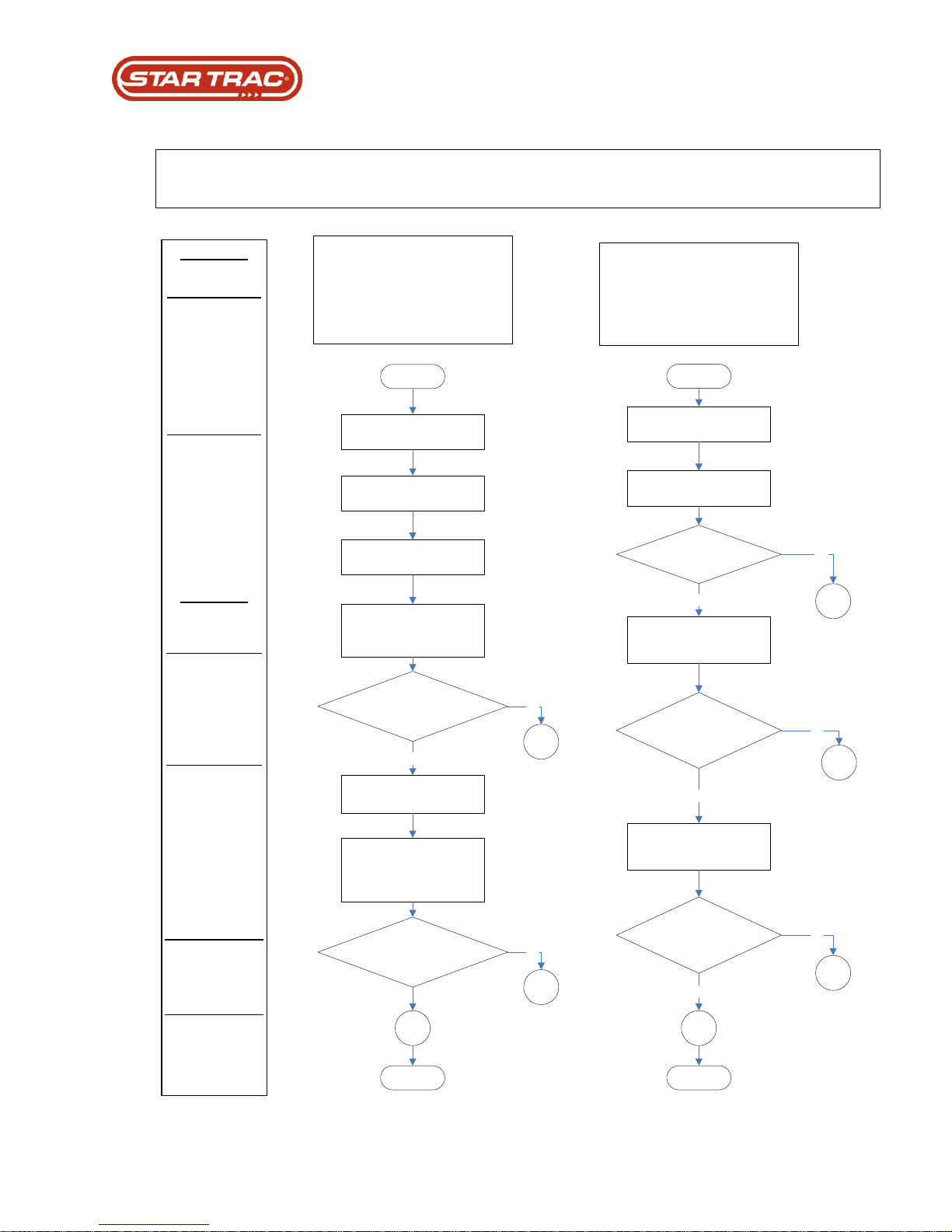
Solution:
__ E1_______
Clean the underneath
side of the running
belt and re-test
Note: If the problem
continues replace the
running belt.
__ E2_______
Replace MCB
Note: Make sure
there’s no objects or
moveable parts that
may cause damage
to the wire.
_________________
_________________
Solution:
__ F1________
Replace MCB
Note: If AC LED is
on and get this error,
replace the MCB.
__ F2________
Reconnect display
cable and re-test
Note: If AC LED is
not on check the I/O
interface cable and
connection. A speed
command with the
relay off will cause
this error.
__ F3________
Replace I/O Interface
cable (Display cable)
__ F4________
Replace I/O Interface
cable (Display cable)
and if the error still
occurs replace the
MCB
Start
Recycle the tread AC power
by turning it off and back on
Engage motor test mode
Incline the unit to max
elevation
Stand at the highest point of
the incline and push body
weight back
Does
the running belt slide
smoothly across
deck?
Yes
No
E1
Decline unit back to zero
percent in test mode.
Increase the speed to 2 MPH
and attempt to push the
belt back faster that the
commanded speed.
Does the
running belt hold strong to it’s
commanded speed?
E1
E2
No
Start
Recycle the tread AC power
by turning it off and back on
Check AC LED on MCB to
see if it’s lit.
Does the AC LED off?
F1
Yes
No
Check I/O cable (display
cable) at the display and
MCB for bad connection
Was the I/O cable
(display cable) making a
good connection?
F2
No
Check I/O cable (display
cable) pinched or damaged
wires
Yes
Was the I/O cable
(display cable) pinched or
damagd?
F3
F4
No
Yes
End End
DFR Code = 800
Phase Over Current / 12 Blinks
Possible Causes:
(1) Worn running belt.
(2) Dirty running belt
(3) Faulty MCB.
DFR Code = 400
Illegal Speed Command / 11 Blinks
Possible Causes:
(1) Pinched or damaged display cable.
(2) Bad wire connection to drive system
(3) Faulty MCB.
DFR CODE FLOWCHART: DEFINITIONS / MCB LED Blinks
DFR Flowchart For #: 800, and 400
Last updated 03/06/2017 637-4504 Rev. B
Page 78
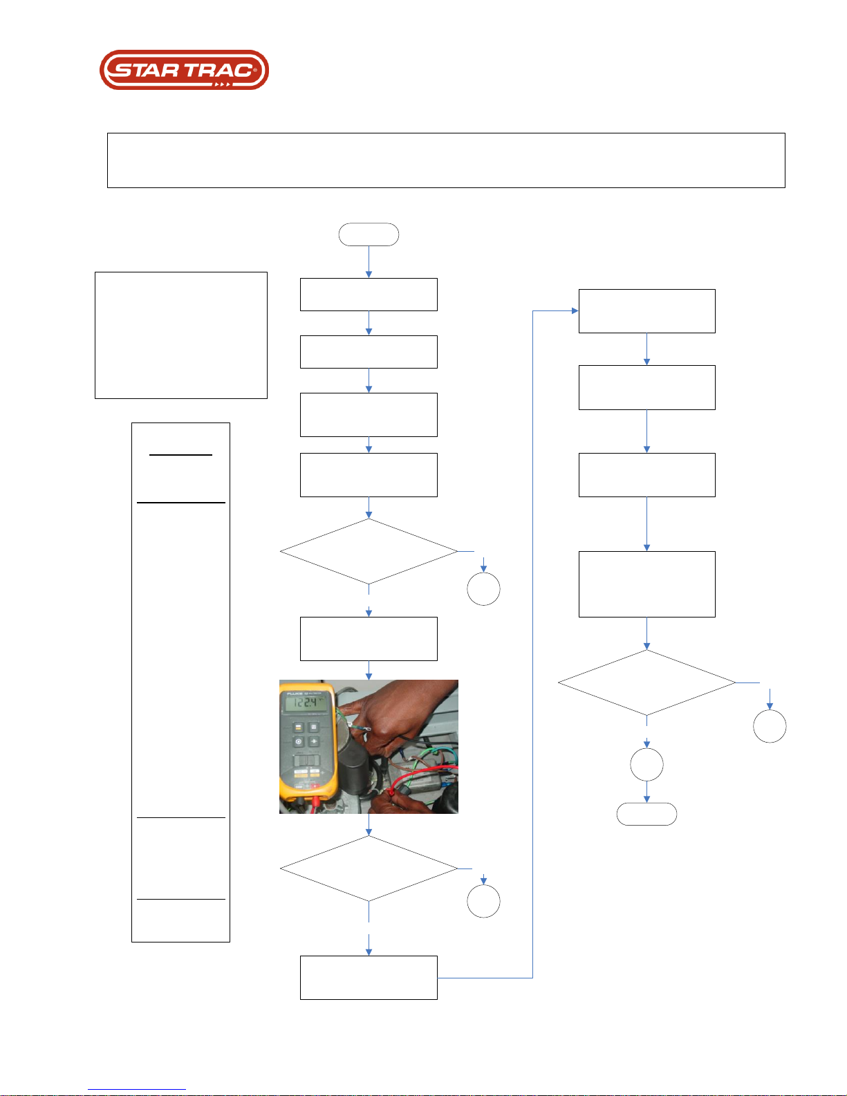
Solution:
__ G1_______
Consult with
electrician to fix AC
input rail voltage.
Note: The AC rail
voltage with a load
should never drop
greater that 5 volts
deferential comparing
it with no load. There
are many equations
to measure for low
rail voltage.
Example: If you take
a person that weighs
200 Lbs at the speed
of 5 MPH, and the
voltage drops greater
that 5 Vac. The wall
voltage is not
adequate and will
cause intermittent
200 DFR codes.
__ G2_______
Replace EMI Filter
__ G3_______
Replace MCB
Start
Turn the tread AC power off.
Measure AC voltage out of the
wall circuit.
Was the AC voltage within
the specs listed above?
The AC voltage should be
approximately:
95 to 120 for 110v unit
The AC voltage should be
approximately:
185 to 250 for 220v unit
G1
No
Check Ac output voltage
coming out of the EMI filter
Was the AC voltage within
the specs listed above?
G2
No
Yes
Engage maintenance mode
(0, 2, start simultaneously)
Yes
Engage motor test mode
(#8 after engaging
maintenance mode)
Increase the speed to 5 MPH
or greater.
Measure AC input voltage with
a load
Was the voltage greater
Than 5 volt deferential?
The input AC voltage should
be less that 5 volt deferential
from the original AC voltage
that was taken with out a load
G1
G3
No
Yes
End
DFR Code = 200
DC Link Bus Under Voltage / 10 Blinks
Possible Causes:
(1) Low AC voltage from wall.
(2) Low AC voltage from EMI filter.
(3) Faulty MCB.
DFR CODE FLOWCHART: DEFINITIONS / MCB LED Blinks
DFR Flowchart For #: 200
Last updated 03/06/2017 637-4504 Rev. B
Page 79
Start
Recycle the tread AC power
by turning it off and back on
Solution:
__ H1_______
Replace MCB
__ H2_______
Replace I/O cable
__ H3_______
Reinsert the phase
wires into the honest
connector.
Note: If the wire
continues to make a
bad connection
replace drive motor.
There is a relay on the MCB
that will activate when turning
the AC power on when unit is
in operable condition.
Did the
display beep with
out the relay switch
activating?
Check I/O cable (display cable)
for pinched or damaged wires.
Yes
H1
No
Was the I/O cable
in good condition?
Check the phase wires on the
drive motor for good
connection in the motor honest
connector or damaged wire.
Yes
Was there a damaged
wire or bad connection on phase
wires to honest connector?
H2
No
H3
H1
Yes
No
End
DFR Code = 40
Phase A Circuit Open / 7 Blinks
DFR Code = 20
Phase B Circuit Open / 6 Blinks
DFR Code = 10
Phase C Circuit Open / 5 Blinks
Possible Causes:
(1) Bad wire connection on drive motor.
(2) Open phase wire in drive motor.
(3) Faulty MCB.
DFR CODE FLOWCHART: DEFINITIONS / MCB LED Blinks
DFR Flowchart For #: 40, 20, and 10
Last updated 03/06/2017 637-4504 Rev. B
Page 80
DFR Code = 2000
Heat Sink Over Temp / 14 Blinks
DFR Code = 100
Critical DC Link Bus Over Voltage (MAX
_VDC2) / 9 Blinks
DFR Code = 80
DC Link Bus Over Voltage (MAX _VDC1) /
8 Blinks
DFR Code = 8
Phase A Current Sensor / 4 Blinks
DFR Code = 4
Phase A Current Sensor / 3 Blinks
DFR Code = 2
1.65 Vdc Ref. Status / 2 Blink
DFR Code = 1
2.5 Vdc Ref. Status / 1 Blink
DFR Code = 800000
Phase C High (Gate Drive Fault) / 24 Blink
DFR Code = 400000
Phase B High (Gate Drive Fault) / 23 Blink
DFR Code = 200000
Phase A High (Gate Drive Fault) / 22 Blink
DFR Code = 80000
Phase C Low (Gate Drive Fault) / 20 Blink
DFR Code = 40000
Phase B Low (Gate Drive Fault) / 19 Blink
DFR Code = 20000
Phase A Low (Gate Drive Fault) / 18 Blink
___________________________________
___________________________________
Possible Causes:
(1) Faulty MCB.
Solution:
__ I1_______
Replace MCB
__ I2_______
Verify the drive
motor, sensor, and
display cable wires
are not damaged and
making a good
connection with
MCB, and re-test.
Note: If all drive
system wires are
making a good
connection replace
MCB.
__ I3_______
If different DFR error
come up refer back
to the DFR flowchart
of the error that’s
coming up.
Start
Recycle the tread AC power
by turning it off and back on
A relay switch should click on
the MCB
Does the relay switch
click on the MCB?
I1
I2
Yes
No
End
Did the
display beep with
out the relay switch
activating?
Yes
Verify the drive motor, sensor,
and display cable wires are not
damaged and making a good
connection with MCB, and re-
test.
Yes
I1
Does the unit error out
with the same DFR code?
Yes
I3
No
DFR CODE FLOWCHART: DEFINITIONS / MCB LED Blinks
DFR Flowchart For #: 2000, 100, 80, 8, 4, 2, 1, 800000, 400000, 200000, 40000, and 20000
Last updated 03/06/2017 637-4504 Rev. B
Page 81
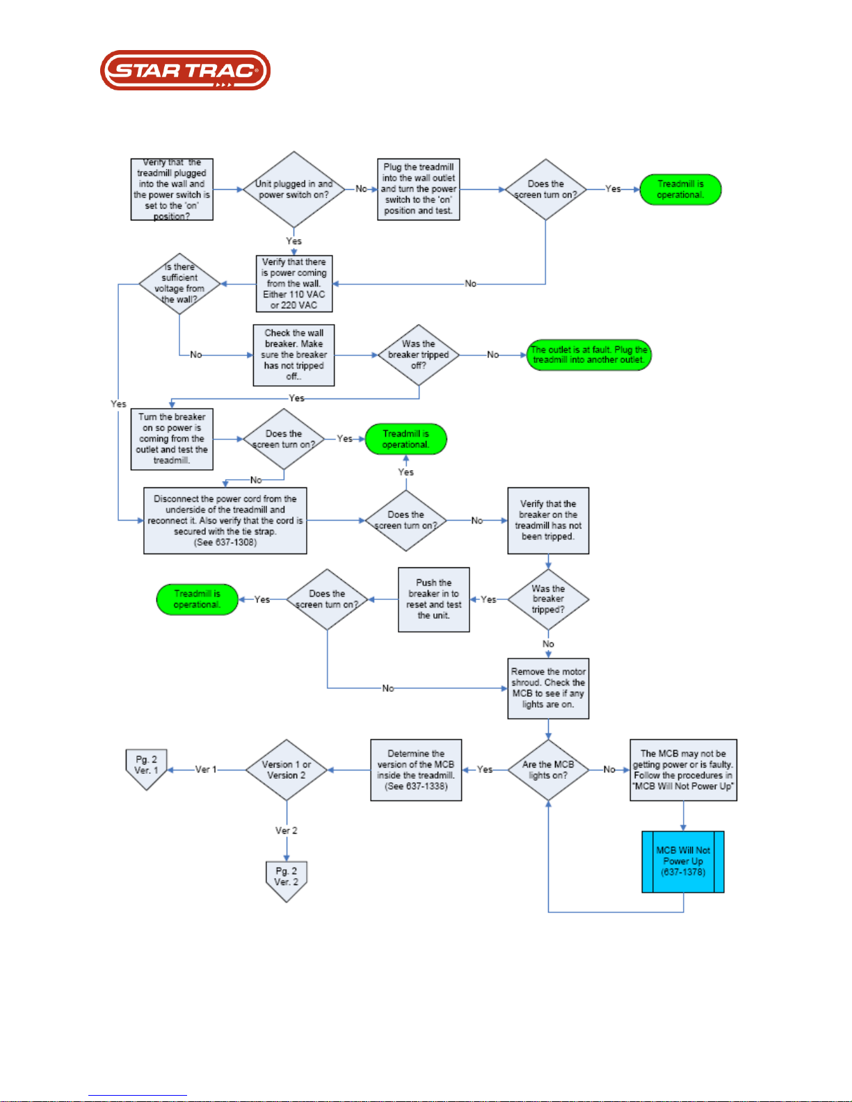
Embedded No Power
Last updated 03/06/2017 637-4504 Rev. B
Page 82
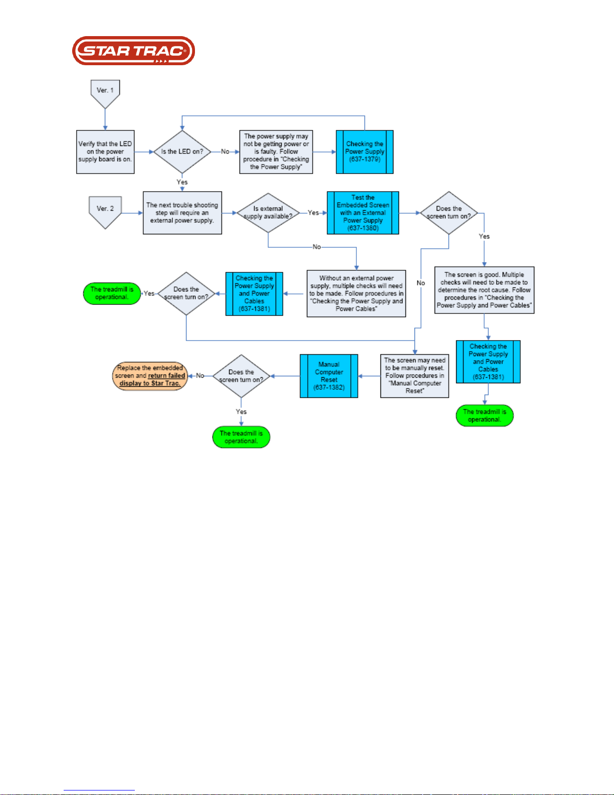
Last updated 03/06/2017 637-4504 Rev. B
 Loading...