

Page 1

STAR TRAC
14410 Myford Road
Irvine, CA 926060 USA
S
P
U
TAR TRAC FITNESS™
ERSONAL VIEWING SCREEN
SER'S
M
ANUAL—
E-S
ERIES
E-TRi
E-UBi, E-RBi, E-STi, E-TBTi
620-7991 Rev 002
Page 2

2
620-7991 Rev 002
Page 3

T
ABLE OF CONTENTS
Introduction .............................................................................................................................................. 4
Before You Get Started ............................................................................................................................ 5
Warnings and Cautions ............................................................................................................................ 6
Important Safety Precautions .................................................................................................................. 7
Unpacking Your Personal Viewing Screen ............................................................................................. 8
Installing your STAR TRAC Personal Viewing Screen ......................................................................... 10
E-UB, E-RB, E-TBT, and E-ST ...................................................................................................... 10
E-TR and ETRx ............................................................................................................................. 19
Setting Up your NTSC / ATSC Personal Viewing Screen ..................................................................... 25
Basic Operations ........................................................................................................................... 25
Adjusting Picture Menu Options .................................................................................................... 26
Adjusting Audio Menu Options ...................................................................................................... 27
Adjusting Setup Menu Options ...................................................................................................... 29
Adjusting Channel Menu Options .................................................................................................. 33
Setting Up your PAL / SECAM Personal Viewing Screen .................................................................... 35
Basic Operations ........................................................................................................................... 35
Adjusting Picture Menu Options .................................................................................................... 36
Adjusting Sound Menu Options ..................................................................................................... 37
Adjusting Time Menu Options ....................................................................................................... 38
Adjusting System Options Menu ................................................................................................... 40
Adjusting Lock Menu Options ........................................................................................................ 41
Adjusting Channel Menu Options .................................................................................................. 43
FAQ’s and Troubleshooting ................................................................................................................... 46
Cleaning the PVS .......................................................................................................................... 46
Troubleshooting ............................................................................................................................ 46
Headphone Jack Replacement ..................................................................................................... 48
Regulatory Information .......................................................................................................................... 49
Copyright 2010. Star Trac by Unisen, Inc. All rights reserved, including those to reproduce this book or parts thereof in any form without first obtaining
written permission from Star Trac.
Every effort has been made to keep this information current; however, periodically, changes are made to the information herein, and these changes will
be incorporated into new editions of this publication. All product names and logos are trademarks of their respective owners. Printed in the USA.
3
620-7991 Rev 002
Page 4

I
NTRODUCTION
Thank you for adding the STAR TRAC PERSONAL VIEWING SCREEN (PVS) to your Star Trac
Purchase. The Personal Viewing Screen has been designed to provide the user with the most rewarding experience based upon the carefully planned features it possesses. The design elements
of this Personal Viewing Screen will provide you with a comfortable, intuitive, safe and reliable experience, guiding you to a habit-forming lifestyle. Star Trac's mission is to provide products to mold
lifelong habits for health and fitness.
ABOUT THIS MANUAL
This manual is applicable to the STAR TRAC E-UB UPRIGHT BIKE, E-RB RECUMBENT BIKE, EST STEPPER, E-TBT TOTAL BODY TRAINER, and the E-TR TREADMILL. The manual is divided
into nine sections, as follows:
Introduction
Provides an overview of each section within the manual.
Before You Get Started
Provides guidelines to help you have a successful installation.
Warnings and Cautions
Helpful safety tips to keep you out of harms way.
Important Safety Precautions
Provides important safety tips to keep you out of harms way.
Unpacking your Personal Viewing Screen
Provides a description of what you will find in your PVS kit.
Installing Your STAR TRAC Personal Viewing Screen (PVS)
Provides a step-by-step instruction set for installing your PVS on the E-UB, E-RB, E-ST, ETBT and E-TR.
Setting Up Your STAR TRAC Personal Viewing Screen (PVS)
Provides step-by-step instruction set for configuring your PVS with either the NTSC/ATSC or
PAL/SECAM screen.
FAQ’s and Troubleshooting
Frequently asked questions and troubleshooting methods to help solve problems that may
occur with your PVS.
Regulatory Information
Provides regulatory information for the Star Trac Personal Viewing Screen.
4
620-7991 Rev 002
Page 5

B
EFORE YOU GET STARTED
C
HECK FACILITIES PREPAREDNESS
For a proper installation, please read this guide thoroughly and follow the instructions. Star Trac’s
goal is to help you have a successful and reliable installation, for this reason we have come up with
some helpful tips and check list to accomplish this goal.
E
QUIPMENT LAYOUT
Check to see that the equipment you will be adding the PVS to are placed where they will be used. It
is recommended that you follow your installation guides for each one of your Star Trac pieces of
equipment in making sure that there is ample space around them to ensure a safe and enjoyable
experience.
I
NPUT SIGNAL
In the world of entertainment today you have many choices. Star Trac recommends you know what
type of video signal (cable, analogue, digital, satellite, antenna) is in the club facility and if it has a
good signal. Don’t forget every installation is different. Check to see that you have a coaxial cable
connection at each location where a PVS will be installed.
C
ABLING
When Radio Frequency signals travel through cabling the signal will degrade over distance. Connectors may degrade the signal as well. Check each output before connecting to your PVS and make
sure you have a clean strong signal to ensure an enjoyable experience. The Star Trac PVS requires
a minimum signal strength of 45dBmV for analogue channels, and 40% for digital channels. Your
club may require signal amplifiers to achieve a good strong signal. Star Trac recommends you use a
qualified installer for your Audio Visual needs.
E
LECTRICAL RECEPTACLES
The Personal Viewing Screen requires a plug-in 60 watt power supply to operate (included). Check
with your club facility to ensure ample electrical receptacles are placed next to the equipment for a
safe and proper install. Check with your contractor to make sure you have enough power.
5
620-7991 Rev 002
Page 6
W
ARNINGS AND CAUTIONS
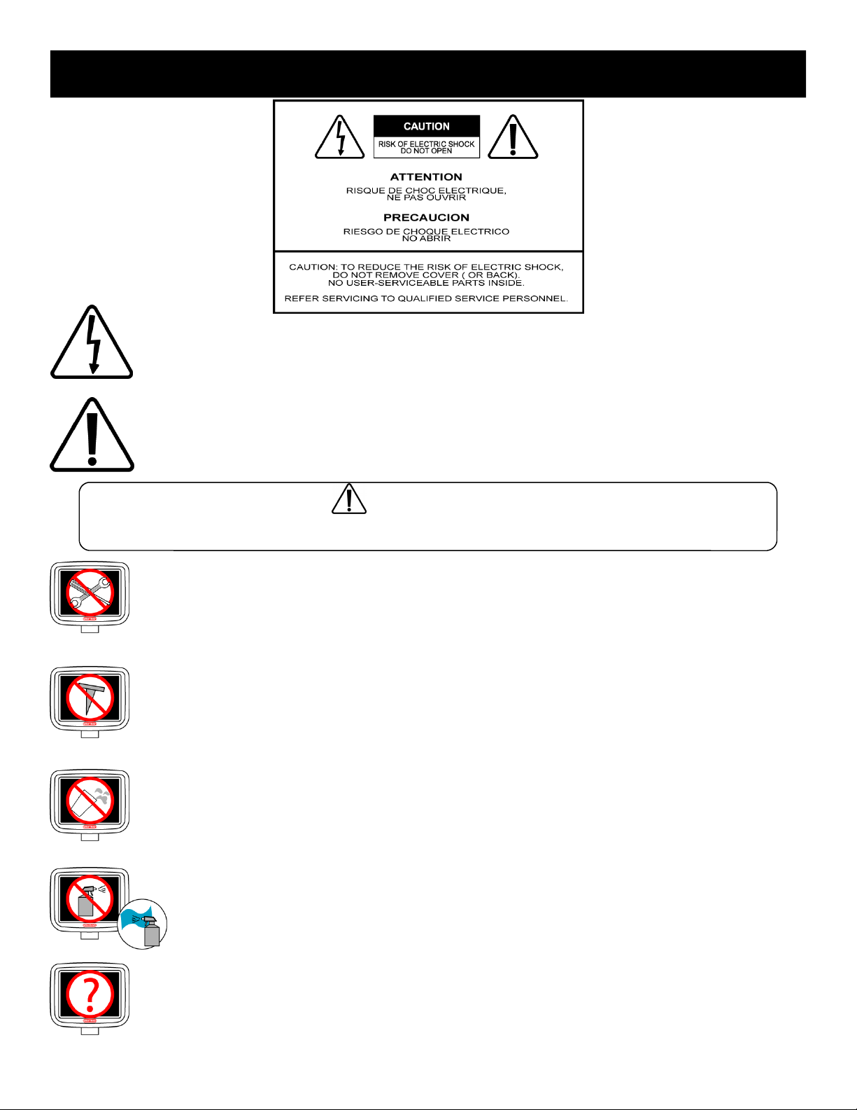
This lighting flash with arrowhead symbol, within an equilateral triangle, is intended to alert
the user to the presence of un-insulated “dangerous voltage” within the product’s enclosure that may be of sufficient magnitude to constitute a risk of electric shock to persons.
This exclamation point within an equilateral triangle is intended to alert the user to the
presence of important operating and maintenance (servicing) instruction in the literature
accompanying the appliance.
To reduce the risk of fire or electric shock, do not expose this appliance to rain or moisture.
WARNING:
DO NOT disassemble the PVS.
Any unauthorized maintenance will void the warranty. Inexperienced technicians can cause
serious damage, electric shock, and other hazards.
Contact your dealer or an experienced technician for repair.
DO NOT place sharp tools such as a pin or other metallic object near the display.
May result in scratching the surface of the monitor as well as the frame.
Keep your monitor away from liquid or a humid place.
May cause electric shock and damage the display.
DO NOT spray any fluid directly on the surface of the monitor.
Spray the cleaner fluid on a soft cloth to wipe the surface of the monitor.
When strange sound or smoke occurs, be sure to unplug your power cord.
These problems can cause a serious electric shock and other hazards.
6
620-7991 Rev 002
Page 7

I
MPORTANT SAFETY PRECAUTIONS
Electrical energy can perform many useful functions, but it can also cause personal injuries and property
damage if improperly handled. This product has been engineered and manufactured with the highest priority on safety. But IMPROPER USE CAN RESULT IN POTENTIAL ELECTRICAL SHOCK OR FIRE HAZARD. In order to prevent potential danger, please read the following instructions when installing, operating
and cleaning the product. To ensure your safety and prolong the service life of your new product, please
read the following precautions carefully before using the product.
1. Read these instructions---All operating instructions must be read and understood before the product is
operated.
2. Keep these instructions---These safety and operating instructions must be kept in a safe place for fu-
ture reference.
3. Heed all warnings---All warnings on the product and in the instructions must be observed closely.
4. Follow all instructions---All operating instructions must be followed.
5. Power source---This product is intended to be supplied by a listed power supply indicated on the mark-
ing label. If you are not sure of the type of power supply to your home, consult your product dealer or
local power company. For added protection for this product during a lightning storm, or when it is left
unattended and unused for long periods of time, unplug it from the wall outlet and disconnect the cable
system.
6. Power cord protection---Protect the power cord from being walked on or pinched particularly at plugs,
convenience receptacles, and the point where they exit from the apparatus.
Note: where the mains plug or an appliance coupler is used as the disconnect device, the disconnect
device shall remain readily operable.
7. Overloading---Do not overload wall outlets, extension cords, or convenience receptacles on other
equipment as this can result in a risk of fire or electric shock.
8. Replacement parts---In case the product needs replacement parts, make sure that the service person
replaces parts specified by the manufacturer, or those with the same characteristics and performance
as the original parts. Use of unauthorized parts can result in fire, electric shock and/or other dangers.
9. Safety checks---Upon completion of service or repair work, request the service technician to perform
safety checks to ensure that the product is in proper operating condition.
10. Clean only with damp cloth---Unplug this product from the wall outlet before cleaning. Do not use liq-
uid cleaners or aerosol cleaners. Use a damp cloth for cleaning.
11. Panel protection---The display panel used in this product is made of glass. Therefore, it can break
when the product is dropped or impacted upon by other objects. Be careful not to be injured by broken
glass pieces in case the display panel breaks.
12. Pixel defect---The display panel is a very high technology product, giving you finely detailed pictures.
Occasionally, a few non-active pixels may appear on the screen as a fixed point of blue, green or red.
Please note that this does not affect the performance of your product.
Warning:
To prevent the spread of fire, keep candles or other open flames
away from this product at all times.
7
620-7991 Rev 002
Page 8

U
NPACKING YOUR PERSONAL VIEWING SCREEN
Inspect the shipping box for any parts that may be missing BEFORE discarding the box. Items can shift during transportation, and may be accidentally discarded with the box. If any parts are missing, please contact
Star Trac Product Support at 800-503-1221. Have the serial number of the PVS, and a list of the missing
parts ready so they may be shipped to you. The Personal Viewing Screen is shipped in one box separate
from your exercise equipment.
PVS kits are available in two different signal formats; NTSC/ATSC (typically US, Japan) and PAL/SECAM
(typically Europe, Middle East), make sure the kit you have is appropriate for the country of the club facility.
The following items will be in the box:
NTSC/ATSC Kit (US, Japan)
•
PVS assembly with mounting bracket, cables, and display cap with grommet
•
Center console keypad assembly
•
Entertainment headphone jack and Mount
•
Hardware tool kit, including:
•
(1) Headphone icon
•
(4) M8 x 20mm buttonhead screws
•
(5) M4 x 0.7X19L screws
•
(1) M8 hex nut
•
(1) Silicone wrap
•
(2) 5” tie straps
•
5MM hex Allen key.
•
60w power supply
•
Power cord, AS/NZS 3112
•
Power cord, Nema 6-15
•
Power cord, Nema 5-15
•
Owners manual
•
Warranty card.
(NOT INCLUDED IN THE E-TRi KIT)
(NOT INCLUDED IN THE E-TRi KIT)
(NOT INCLUDED IN THE E-TRi KIT)
(NOT INCLUDED IN THE E-TRi KIT)
(There are 5 cables in the neck)
8
620-7991 Rev 002
Page 9

PAL/SECAM Kit (Europe, Middle East)
•
PVS assembly with mounting bracket, cables, and display cap with grommet
•
Center console keypad assembly
•
Entertainment headphone jack and mount
•
Hardware tool kit, including:
•
60w power supply
•
Power cord, CEE 7/7
•
Power cord, Nema 6-15
•
(1) Headphone icon
•
(4) M8 x 20mm buttonhead screws
•
(5) M4 x 0.7X19L screws
•
(1) M8 hex nut
•
(2) 5” tie straps
•
Silicon wrap
•
F-type male to female PAL/SECAM coaxial adapter
•
5MM hex Allen key.
(NOT INCLUDED IN THE E-TRi KIT)
(NOT INCLUDED IN THE E-TRi KIT)
(NOT INCLUDED IN THE E-TRi KIT)
(There are 5 cables in the neck)
•
Power cord, BS 1363
•
Owners manual
•
Warranty card.
(NOT INCLUDED IN THE E-TRi KIT)
Required Tool for Installation
•
5MM hex Allen key
•
#2 Phillips screwdriver
•
1/2” wrench
•
Wire cutters
•
Pliers
•
Step stool
(Not Included)
(for E-TRi kits only, not included)
(Not Included)
(Not Included)
(Not Included)
9
620-7991 Rev 002
Page 10
I
NSTALLING YOUR PVS ON THE E-UB, E-RB, E-TBT, AND E-ST
The Star Trac Personal Viewing Screen is different for each of your Star Trac E-Series Cardio products. Make sure you have the proper kit for the E-Series product you are installing. The E-UBi, ERBi, E-TBTi, and the E-STi will follow the same basic steps for installation. For the E-TRi turn to appropriate section of this manual.
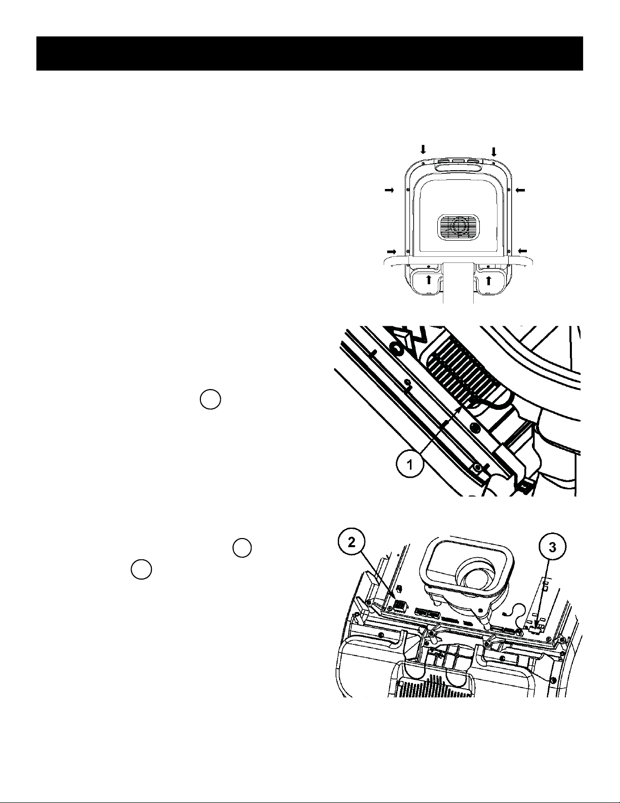
STEP 1.
Using a #2 Phillips screwdriver, remove the (8)
screws on the back of the display plastic. Set
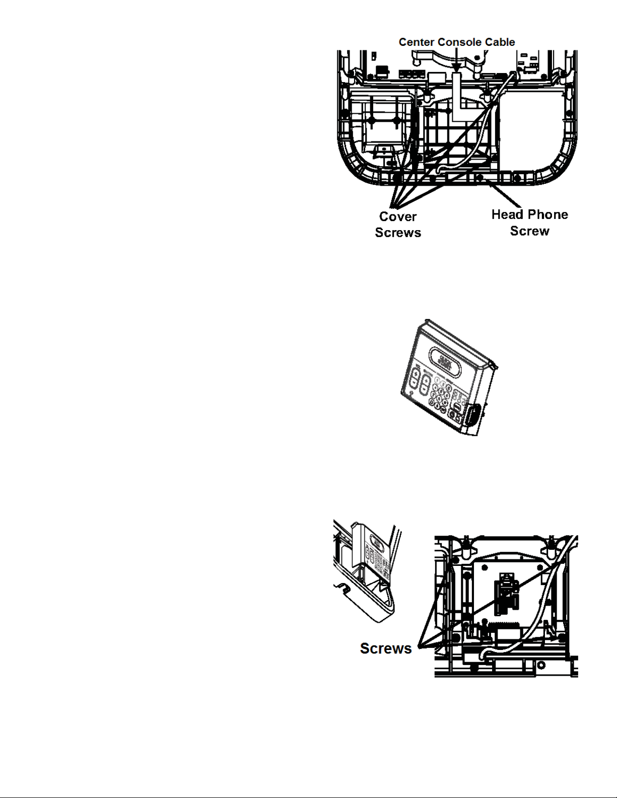
the screws aside, you will need them for reassembly.
STEP 2.
After the screws have been removed, carefully
open the display plastic, so as to not detach the
inner cables from the display.
Disconnect the ground wire between the
heart rate board and the display mount.
1
STEP 3.
Disconnect the 12-pin serial cable and the
heart rate cable from the display.
After all the cable/harnessing has been disconnected, place the front display plastics aside for later
use. Be careful with the display and place it face down on top of a non-scratching surface.
10
3
2
620-7991 Rev 002
Page 11
You can use the foam bag that ships inside the Personal Viewing Screen package to
place the display face onto. This will help protect it from being damaged.
STEP 4.
Remove the cap cover with the Star Trac logo
from the back cover plastics by removing the (2)
screws using a #2 Phillips screwdriver. Retain
the screws for later use.
You will no longer need the cap cover and, if desired,
you can store it away for any possible future use.
STEP 5.
Remove the (2) M8 buttonhead screws retaining
the cross-brace using provided 5mm Hex key.
Retain screws for later use.
You will no longer need the cross-brace and, if desired, you can store it away for any possible future
use.
STEP 6.
It is now time to install the Personal Viewing
Screen. Remove the PVS with its mounting
bracket and cables from the packaging. Also remove the (2) M8 buttonhead screws from the
hardware kit in the packaging.
11
620-7991 Rev 002
Page 12
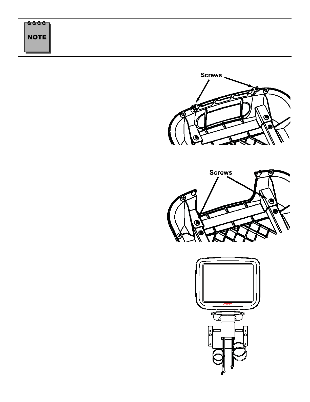
STEP 7.
Mount the PVS assembly on the mounting
bracket, then thread the (4) M8 buttonhead
screws through the PVS mounting bracket into
the display mount. Do not tighten the screws yet.
Note:
(2) of the screws are in the PVS kit, (2) retained from
step 5.
STEP 8.
Adjust the cap with the grommet into place. Using
the 5mm Hex key, tighten the M8 buttonhead
screws to 190 lb-in (21.5 N-m) of torque. Take
the (2) Phillips head screws you removed from
the original cap and snugly tighten screws down
using a #2 Phillips screwdriver.
Check the back side of the display to see that the cap is seated properly. If not, loosen
the two Phillips Head Screws, adjust the cap and then retighten the screws.
STEP 9.
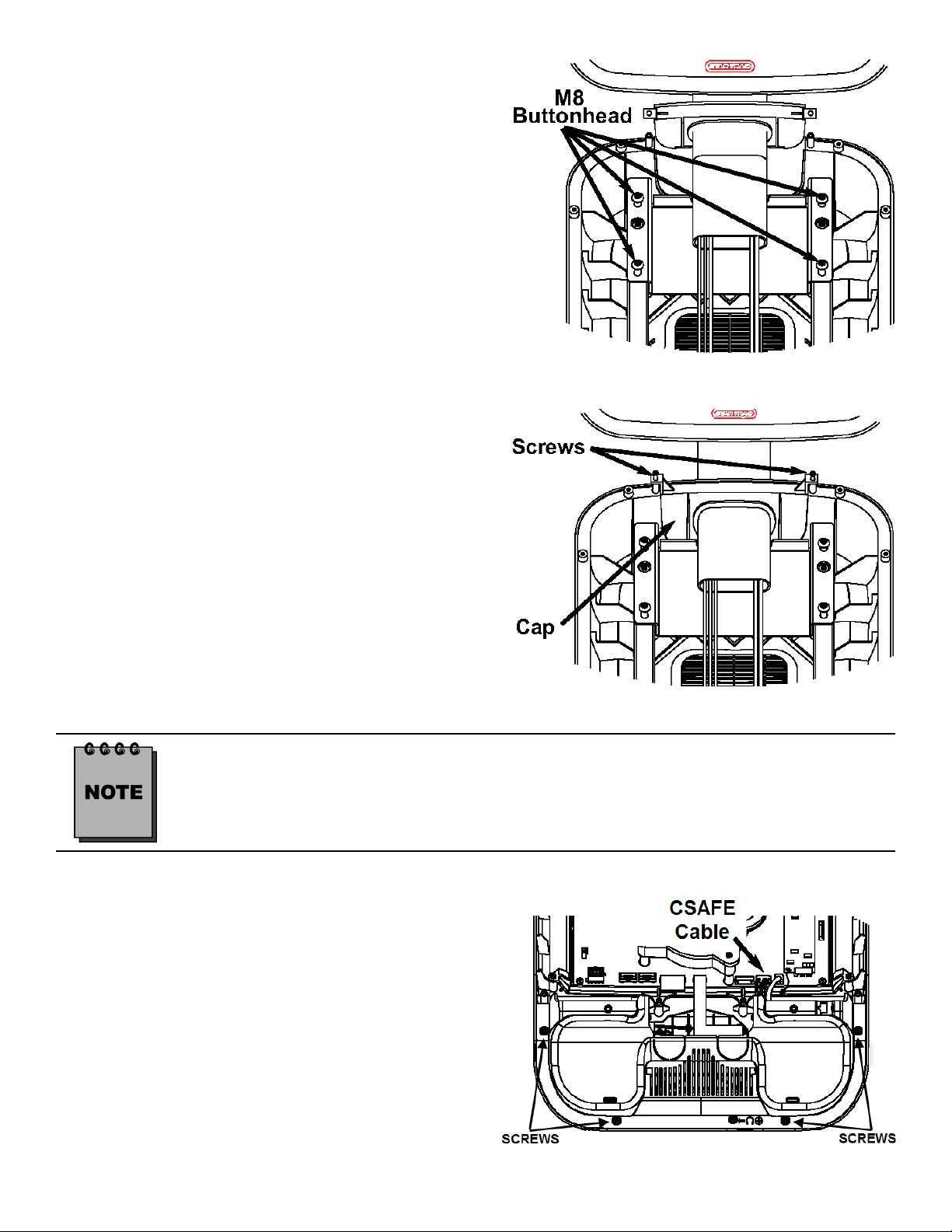
Using a #2 Phillips head screwdriver, remove
the (4) screws that hold bottom side of the display console on. Next remove the bottom cover.
Caution: When removing bottom cover, gently
disconnect the CSAFE cable from the back of
the display board.
Retain screws for later use.
12
620-7991 Rev 002
Page 13
STEP 10.
Using a #2 Phillips head screwdriver, remove
the (4) screws that hold center console to the
display and remove the screw that holds in the
blank cover where the new headphone jack
mount will go.
Next detach the center console ribbon cable
then remove the center console and the blank
headphone cover. Retain screws for later
use.
Note: You will no longer need the center console
and headphone jack cover, both can be stored away
for any possible future use.
STEP 11.
Take the new PVS center console from the kit.
STEP 12.
insert the new center console into the front display. Using a #2 Phillips screwdriver, screw in
the (4) screws that were saved from the original
center console. Tighten the screws so they are
snug.
13
620-7991 Rev 002
Page 14
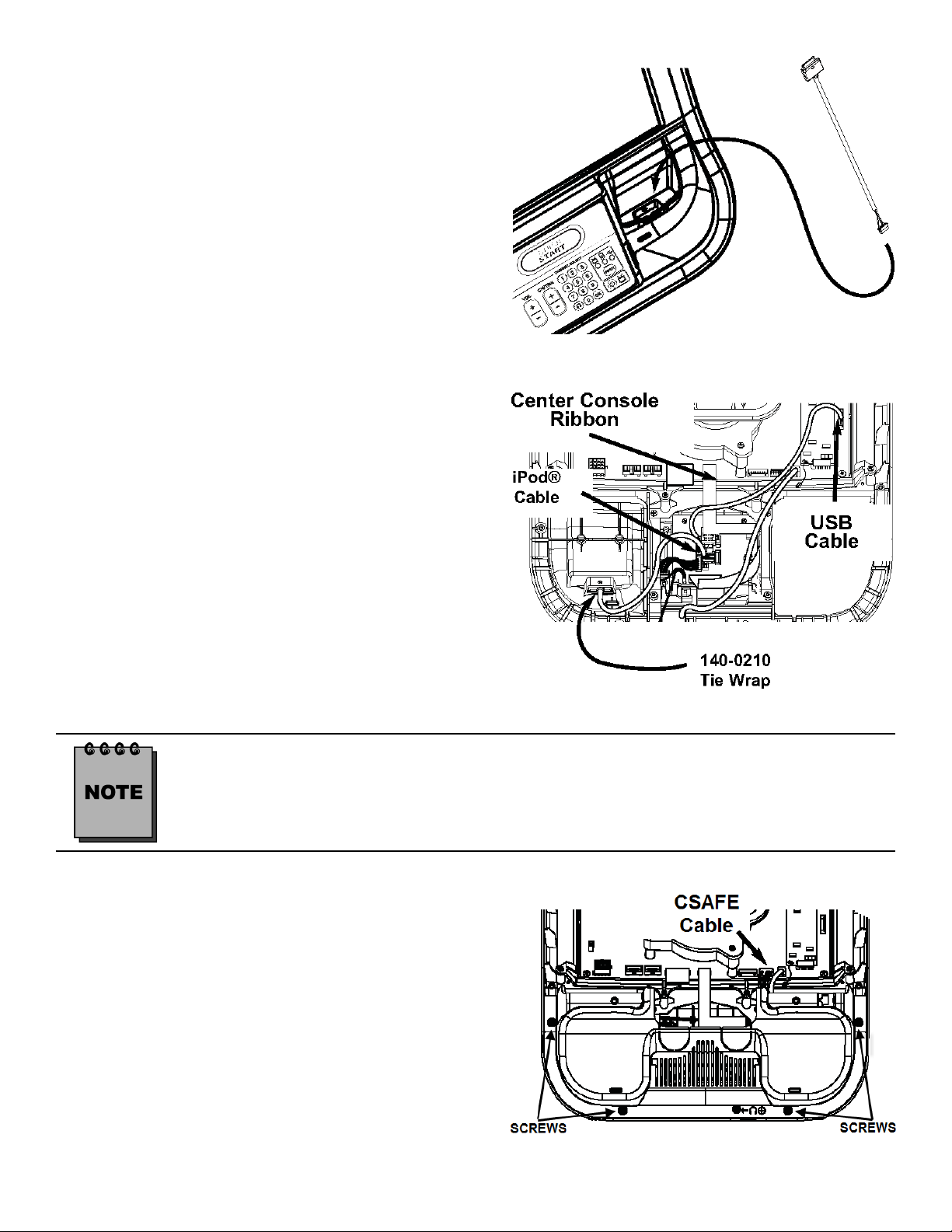
STEP 13.
Note: If the iPod cable comes pre-installed on the cradle,
skip this step.
Take the iPod® cable from the kit. Install the
cable into the iPod® cradle on the front side of
the display console by removing the plug from
the cradle then inserting the cable through opening. Make sure cable is aligned properly with the
display plastics. Press firmly to ensure the cable
is seated into the cradle.
STEP 14.
With the center console now installed, it is time
to attach the USB cable, center console ribbon
and the iPod® cable. Take the USB cable from
the center console and attach it to the CCB J14
connector on the display board. Next take the
center console ribbon cable and attach it to the
display PC board. Then take the iPod® cable
from the base of the mount to the center console. Tie the iPod® cable to the plastic using the
3.5” tie wrap.
Make sure pin one on the cable is connected to pin one on the board.
STEP 15.
Next replace the bottom cover. Using a #2 Phillips head screwdriver, replace the (4) screws
that hold the bottom side of the display console
on. Then plug in the CSAFE cable to the back of
the display board.
14
620-7991 Rev 002
Page 15
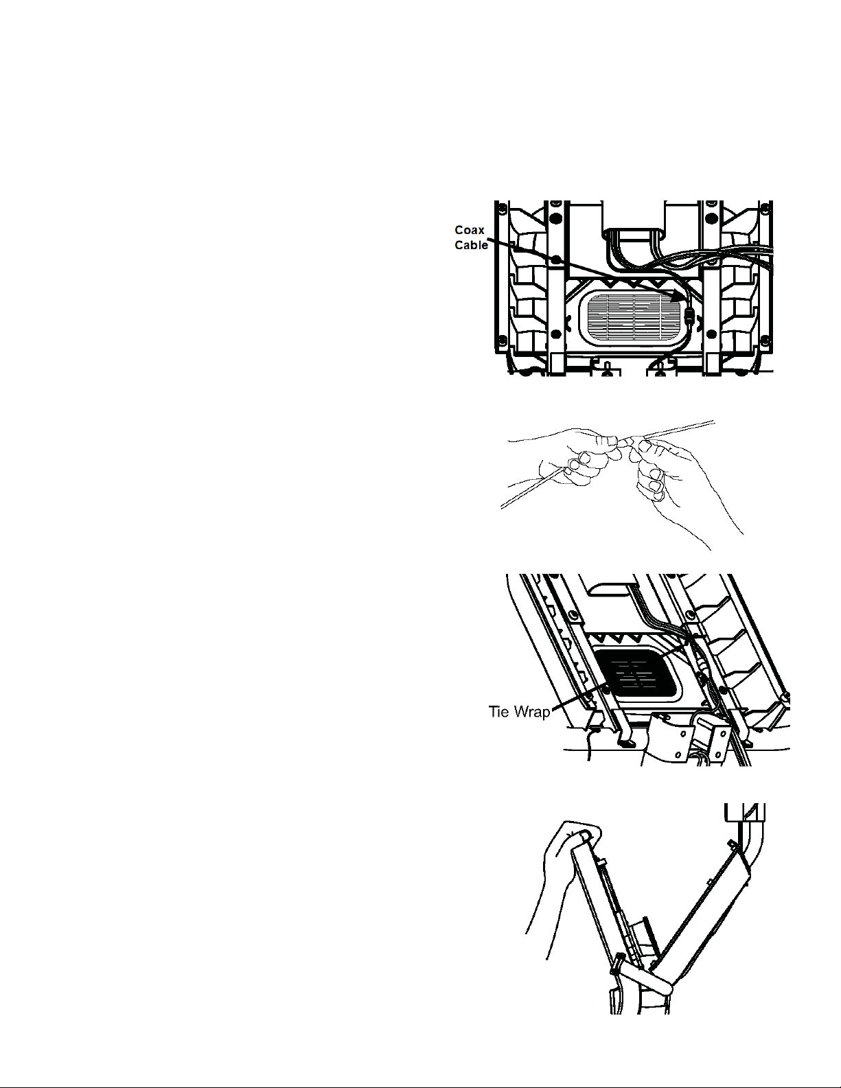
With the changes now completed on the display, it is now time to re-install the display console to the
base unit. There are the (3) cables from the PVS mount that will need to be attached to the display.
One cable from the PVS mount will be fed through the display which will be connected to the head
phone jack later. The fifth cable from the PVS mount, which is the coax, will be connected to the
coax on the base unit. There are (2) cables from the base unit that will be connected to the display.
Use the image below to help reference the needed points on the display.
STEP 16.
Take the coax cable from the PVS mount and
attach it to the coax cable on the base unit.
Tighten the connectors snug to each other.
STEP 17.
Now take the 5” silicon wrap from the kit and
peel off its protective tape then wrap the two
connectors so that all of the metal surface is
covered
STEP 18.
Using a 5” tie wrap from the PVS kit, bind the
cables from the PVS neck to one side of the
display mount. Take the tie and put it through
the hole on one of the display mount tubes.
STEP 19.
Now, take the front display plastics with the new
center console to the base unit. Hold the front
display plastics at the top with one hand while
connecting the cables/harnesses with the other.
There is no particular order in connecting the
cables. However, it may be best to start off connecting the cables/harnessing coming from the
neck of the base unit.
15
620-7991 Rev 002
Page 16
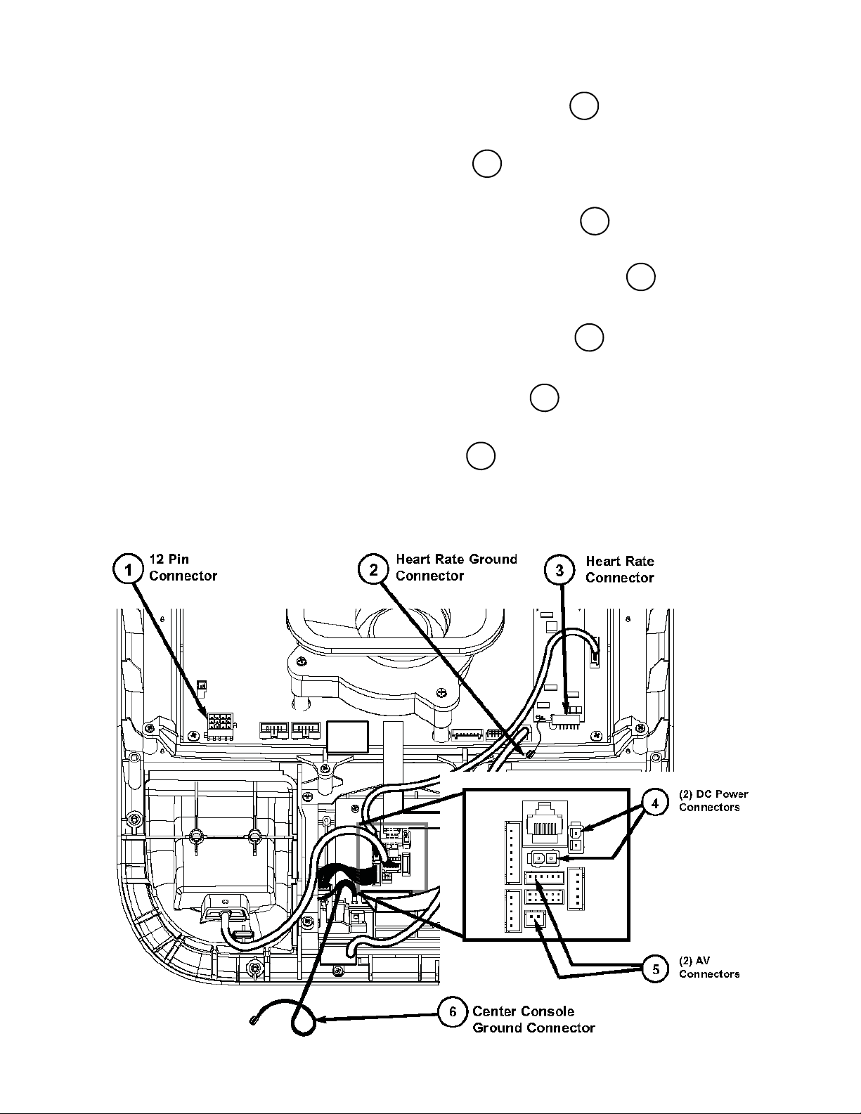
STEP 20.
•
•
•
•
•
•
•
5
1
3
4
4
Connect the 12 pin serial cable from the base frame neck to the 12 pin socket on the display.
Connect the ground cable from the front display heart rate board to one of the terminals
on the display mount.
Connect the heart rate cable from the display support tube to the heart rate board on the
display.
Connect the DC power from the base frame neck to either one of the DC connectors on
the front display center console board.
Connect the DC power from the PVS display neck to the other DC connector on the front
display center console board
Connect the AV cables from the PVS display neck to the (2) AV connectors on the center
console board.
Connect the ground cable from the front display center console to one of the terminals
on the display mount.
2
6
16
620-7991 Rev 002
Page 17

STEP 21.
Feed the headphone jack cable from the PVS
display neck through the hole in the front display plastics where the blank cover was removed earlier.
STEP 22.
Take the entertainment headphone jack from
the PVS kit and attach it to the cable that is
hanging out of the front of the display. Make
sure the connector is seated all the way into the
jack. Now slide the jack into the front of the display. Using a #2 Phillips screwdriver, fasten the
headphone jack into the front display with the
screw that was saved from the earlier step.
STEP 23.
Now that all the cables are in their places, and
confined to the post on the display mount, place
the display front plastic onto the back. Make
sure the bottom of the display front is under the
2 tabs on the display mount. Press the front display against the round tube and rotate it to the
back. Be careful not to pinch any wires.
17
620-7991 Rev 002
Page 18

STEP 24.
Using a #2 Phillips screwdriver, secure the front
display to the back with the (8) screws you previously removed and saved.
STEP 25.
Now with the Personal Viewing Screen installed
on your Star Trac equipment, it is time to connect your entertainment cable and power to the
unit. Look at the bottom of the neck, next to the
floor. Connect your in-house Entertainment cable to the RF input. Take the power supply from
the PVS kit and plug the small barrel connector
to the DC input. Now take the appropriate
power adapter cable from the kit and plug it into
the power supply and the electrical receptacle.
Only use the power supply that was provided in your Personal Viewing Screen Kit. Using the wrong supply may damage your PVS.
This completes the installation of the Personal Viewing Screen on the E-UB / E-RB / E-TBT / E-ST.
Now it is time to set it up. Turn to the appropriate section for your Personal Viewing Screen.
18
620-7991 Rev 002
Page 19

I
NSTALLING YOUR PVS ON THE E-TR AND E-TRx
STEP 1.
Using a #2 Phillips screwdriver, remove the (8)
screws from the upper back of the display.
Place the cover somewhere safe to keep it from
being damaged. Next, remove the (6) screws
from the lower back of the display. Place the
cover with the other one. Retain all the screws
for later use.
STEP 2.
Now remove the upper cap cover that has the
STAR TRAC logo on it. This cap is held in by
the upper back cover.
You will no longer need this cap cover and, if desired, you can store it away for any possible future
use.
STEP 3. (E-TRx ONLY)
Note: If you have an E-TR skip this step.
Using a #2 Phillips screwdriver, remove the
screw that holds in the blank headphone jack
cap at the lower front of the Hot Bar. Retain the
screw.
You will no longer need the cap and, if desired, you
can store it away for any possible future use.
Now take the headphone jack from the iPod®
CC hardware kit. Connect the headphone jack
to the cable in the jack opening. Use the previously retained screw to reinstall the headphone
jack. Tighten snugly.
Skip ahead to Step 5.
19
620-7991 Rev 002
Page 20

STEP 4. (E-TR ONLY)
Using a #2 Phillips screwdriver, remove the
screw that holds in the blank headphone jack
cap at the lower front of the display. Retain the
screw.
You will no longer need the cap and, if desired, you
can store it away for any possible future use.
Now take the headphone jack from the iPod®
CC hardware kit. Connect the headphone jack
to the cable in the jack opening. Use the previously retained screw to reinstall the headphone
jack. Tighten snugly.
STEP 5.
Detach the center console ribbon cable from the
display board by gently pulling on the ribbon
connector. Using a #2 Phillips screwdriver to
remove the (4) screws that hold the center console in place. Retain the screws for later use.
Remove the center console.
need this center console and, if desired, you can
store it away for any possible future use.
You will no longer
STEP 6.
Take the Personal Viewing Screen from the
PVS kit. Next, take the (3) M8 buttonhead
screws, the M8 Hex nut with washer, and the
5mm Hex key from the PVS hardware tool kit.
Mount the Personal Viewing Screen on the
treadmill. Using the 5mm Hex key, screw in the
(2) M8 buttonheads at the base of the PVS first
(do not tighten yet). Using the 5mm hex key put
one of the M8 buttonhead screws into the hole
on the PVS neck, then put the Hex nut with
washer on the back side (do not tighten).
STEP 7.
Adjust the display cap up or down to align with
the holes on the display front. Once the cap is
aligned, tighten all three buttonhead screws
with the 5mm hex key.
20
620-7991 Rev 002
Page 21

STEP 8.
Now that the PVS is mounted onto the treadmill, you need to route the wires to their proper
places:
•
Take the coax cable and feed it all the
1
way down the treadmill neck.
•
Feed the DC power cable from the tread-
2
mill neck through the center console hole.
(E-TR ONLY)
•
Next take the headphone jack cable
3
from the PVS neck and connect it to the
headphone jack.
•
Now feed the other (3) cables through
4
the display and out the center console hole.
STEP 9.
Take the entertainment center console from the
PVS Kit.
STEP 10. (E-TRx ONLY)
Take the E-TR headphone jack from the PVS
kit. Disassemble the headphone jack. Retain
the screw and the board.
Take the entertainment center console from the
PVS Kit. Flip it over so you are looking at the
back side.
Mount the headphone jack board to the center
console using the screw from earlier.
NOTE: The headphone jack must be mounted as
seen to reduce interference.
Once the center console has been mounted
into the display connect the head phone jack to
the appropriate jack as noted.
21
620-7991 Rev 002
Page 22

STEP 11.
While holding the new center console near the opening of the display, connect the following cables
to there appropriate connector. (There is no particular order):
•
Plug in the (2) DC power cables to the DC connectors, (they are the same so it does not
matter which goes to which).
•
Plug in the PVS remote cable to the PVS remote connector.
•
Plug in the A/V cable to the audio (6-pin) and the video (2-pin) connector, respectively, to the
A/V connectors on the center console board.
•
Take the keypad tail, and the center console ground and feed them through the cable
window.
1
2
3
4
5
STEP 12.
Close the center console. Using a #2 Phillips
screwdriver, take the screws retained from earlier
and screw in the (4) screws from below that hold
in the center console. Tighten the screws snug.
22
620-7991 Rev 002
Page 23

STEP 13.
•
•
•
STEP 14.
Go to the base of the treadmill neck. Using a #2
Phillips screwdriver, remove the (2) screws that
hold in the RF cable Mounting Bracket. Retain
the screws for later use.
Plug the center console’s ground cable into the quick disconnect tab on the back
display mount.
Connect the keypad tail to the ke y pad connector on the display board.
Connect the interface cable to the Interface connector J11 on the display board.
2
3
1
STEP 15.
Remove the nut and washer from the F-Type
connector on the end of the coax cable you fed
down the treadmill neck, then put connector
through the mounting bracket. Replace the nut
and washer, and tighten the nut snugly.
Next replace mounting bracket into the neck,
using the screws retained from previous step.
Tighten with a #2 Phillips screwdriver.
STEP 16.
Replace the bottom back plastic cover. Using a
#2 Phillips screwdriver insert the (6) screws, retained from earlier step, into the plastic and
tighten snug.
Caution: Do not over tighten screws.
23
620-7991 Rev 002
Page 24

STEP 17.
Replace the top back plastic cover. Using a #2
Phillips screwdriver insert the (8) screws, retained from earlier step, into the plastic.
Do Not tighten screws at this time.
STEP 18.
Check the cap with the neck and grommet.
Make sure the cap is flush with the top back
plastic. Adjust if necessary. Use the screwdriver
to tighten the screws snug from the previous
step.
Caution: Do not over tighten screws.
This completes the installation of the Personal Viewing Screen on the E-TR / E-TRx treadmill.
Now it is time to set it up. Turn to the appropriate section for your Personal Viewing Screen.
24
620-7991 Rev 002
Page 25

S
ETTING UP YOUR PERSONAL VIEWING SCREEN
Basic Operations
(
NTSC / ATSC
)
Turning On / Off the Power
Turning On
Press the button on the control module, the unit will be turned on and you will be ready to use its features.
Turning Off
With the power on, press the button on the control module to turn off the unit.
Note:
•
When selecting AV mode, the button can not work. If you want to turn off the unit, please select TV
mode first.
•
In TV mode, when there is no signal input for 30 seconds, the unit will turn off the back light automatically.
Once you press any button (except button) on the control module or the unit receives a signal input,
the unit will display normally.
•
In AV mode, when there is no signal input for 3-5 seconds, the unit will turn off the back light automatically. When you press VOL+/- button or the unit receives a signal input, the unit will display normally.
Selecting the Input Signal Source
Press the INPUT button repeatedly to select your desired input source. Options include:
•
TV - Watch TV.
•
iPod - Listen to your iPod or watch a movie or other video from your iPod on the PVS screen.
•
USB - Listen to music from your USB device.
Channel Selection
You can use the following ways to change channels:
•
Press CH+ or CH- to go to the next or previous channel. The skipped channels can't be selected.
•
Press the number buttons to directly select any channel you want.
•
To go to the previous channel viewed, press the button.
25
620-7991 Rev 002
Page 26

Adjusting Picture Menu Options
Adjusting the Picture
1. Press VOL+, CH+ and number button [3] at the same time to display the main menu.
2. Press VOL+/- to select Picture menu, press CH- to access the menu.
3. Within the menu, press CH+/-, VOL- to navigate through the options or adjust an option. If the selected
item has submenu, press VOL+ to access.
4. Press VOL+, CH+ and number button [3] at the same time to return to previous menu.
Option Description
Picture Mode
Brightness
contrast
Color
Tint
Sharpness
Color Temperature
Aspect Ration
Select a desired picture mode. You can select from Sport, Custom, Vivid, Standard, Energy Savings and Theater.
Sport: Select for a dynamic picture.
Custom: Select for a customized picture.
Vivid: Select for a bright and vivid picture.
Standard: Select for a standard picture.
Energy Savings: Select for energy savings, the backlight brightness will be decreased.
Theater: Select for a finely detailed picture
Adjusts screen brightness for easier viewing of dark picture such as night scenes and black hair.
Adjusts image contrast.
Adjusts color saturation.
Adjusts tint for image.
Adjusts image sharpness and displays a sharp image.
Select one of three automatic color adjustments. Set to Warm to enhance hotter colors such
as red, or set to Cool to see less intense colors with more blue. You can select from Warm,
Cool and Normal.
You can select the aspect ratio (display proportions) according to your video signal type or
personal preference. You can select from Normal, Zoom, Cinema and Auto.
Normal: Select the correct aspect ratio to match the source’s image. (4:3 to 4:3, 16:9 to 16:9)
Zoom: Enlarges the picture, the top and bottom portion of the picture may be cropped.
Cinema: Stretches the picture at the edges while maintaining a good aspect ratio at the cen-
ter of the screen.
Auto: Select the correct aspect ratio automatically
26
620-7991 Rev 002
Page 27

Adjusting Audio Menu Options
Option Description
Advanced Video
Making use of Advanced Video sub-menu to adjust Noise Reduction, Adaptive Contrast and DCR.
Noise Reduction: Select from Low/Middle/High to reduce noise in the picture, com-
monly called snow. Select Off to turn off this function.
Adaptive Contrast: Select from Low/Middle/High to reduce noise in the picture detail
and brightness.
DCR: Select On to enhance the contrast ratio between light and dark areas of the picture.
Preset
Select Yes then press OK to reset most setting of current source to Picture’s default settings.
Adjusting the Sound
1. Press VOL+, CH+ and number button [3] at the same time to display the main menu.
2. Press VOL+/- to select Audio menu, press CH- to access the menu.
3. Within the menu, press CH+/-, VOL- to navigate through the options or adjust an option. If the selected
item has submenu, press VOL+ to access.
4. Press VOL+, CH+ and number button [3] at the same time to return to previous menu.
27
620-7991 Rev 002
Page 28

Adjusting Audio Menu Options
Option Description
Audio Mode
Select a desired audio mode. You can select from Custom, Standard, Movie and
News.
(Continued)
Bass
Treble
Balance
Audio Source
(Only for analog Programs)
Custom: Select for a customized sound mode.
Standard: Select for normal program.
Movie: Select for movie program.
News: Select for news program.
Adjusts Bass (low sounds).
Adjusts Treble (high sounds).
Adjust volume balance (left and right volume)
Select a desired audio source. You can select from Mono, Stereo and Sap.
Mono: Select for mono reception. Use to reduce noise during weak stereo broadcasts.
Stereo: Select for stereo reception when viewing a program broadcast in stereo.
Sap: Select to automatically switch the TV to second audio programs when this signal is
received.
Audio Language
(Only for digital programs)
SPDIF
(Only for digital programs)
AVL
(Auto Volume Limit)
SRS
Preset
Select an alternate language if the program has more than one language.
Select the digital audio output mode for SPDIF. You can select PCM or RAW.
Select On to adjust the volume by lowing the sound output when the modulation signal
is high.
Select Off to turn off this function.
Select On to turn on the surround sound effect. The benefits of surround sound are
enormous. You can be completely enveloped in sound, just as if you were at a concert
hall or cinema. Select Off to turn off surround sound.
Select Yes then press OK to reset most setting of current source to Audio’s default settings.
28
620-7991 Rev 002
Page 29

Adjusting Setup Menu Options
System Setup
1. Press VOL+, CH+ and number button [3] at the same time to display the main menu.
2. Press VOL+/- to select Picture menu, press CH- to access the menu.
3. Within the menu, press CH+/-, VOL- to navigate through the options or adjust an option. If the selected
item has submenu, press VOL+ to access.
4. Press VOL+, CH+ and number button [3] at the same time to return to previous menu.
Option Description
Menu Language
Time
Select on-screen menus language
Making use of Time sub-menu to set the current time for the set.
Time Mode:
When selecting Auto, the Year, Month, Day and Time information will be displayed
automatically.
When selecting Manual, you can set time manually. The Time Zone and Daylight Sav-
ings items are not selectable.
Time Zone: Select your viewing area time zone.
Daylight Savings: Select On to observe daylight saving time.
29
620-7991 Rev 002
Page 30

Adjusting Setup Menu Options
Option Description
(Continued)
Transparency
Password Setting
Parental Control
(Only for TV Mode)
Select a desired menu transparency.
Used to set a new system password or to change an existing 4-digit system password.
(default password is 0000).
If you forget the password the unit provides a super password “2580”. Please DO NOT
let your children know the super password.
Parental Control enables parents to prevent their children from watching inappropriate
material on TV. Please input the password to enter the Parental Control sub-menu.
Block Unrated TV: Blocks TV programs that do not have a rating.
USA Parental Locks / Canadian Parental Locks: You can set parental controls for the
U.S. and Canada. The following procedure shows how to set controls for U.S. TV ratings. You use similar steps for controlling U.S. movie and Canadian TV ratings.
30
620-7991 Rev 002
Page 31

Adjusting Setup Menu Options
Option Description
Parental Control
(Continued)
(Continued)
U.S. movie (MPAA) ratings
None
G
PG
PG-13
R
NC-17
X
Canadian English ratings
E
C
C8+
G
PG
14+
Movie is not rated.
General audiences.
Parental guidance suggested.
Suitable for children 13 and older.
Parental guidance is suggested
for children under 17.
No suitable for children under 17.
Adult only.
Exempt programming
Suitable for all children.
Suitable for children 8 years and
older.
General audiences.
Parental guidance suggested.
Suitable for children 14 and older
U.S. TV ratings (age-based)
None
TV-Y
TV-Y7
TV-G
TV-PG
TV-14
TV-MA
Canadian French ratings
E
G
8 ans+
13 ans+
16 ans+
18 ans+
TV is not rated.
All children
Suitable to children age 7 and older.
General audience.
Parental guidance suggested
Parents guidance strongly suggested.
Mature audience only.
Exempt programming.
General audiences.
Suitable for children 8 years and older.
Suitable for children 13 years and older.
Suitable for children 16 years and older.
Adults only.
18+
RRT5 Setting: You can download rating information to use when setting parent controls.
Note: The actual menu options of this rating vary.
Adults only.
31
620-7991 Rev 002
Page 32

Adjusting Setup Menu Options
(Continued)
Option Description
Closed Caption Allows you to select feature On or Off
On: Turns on the Closed Caption.
Analog Caption
Digital Captions
(Only for digital programs)
Digital Captions
Setup
(Only for digital programs)
Off: Turns off the Closed Caption.
Allows you to select closed caption options.
CC1, CC2, CC3, CC4:
Displays a printed version of the dialog or sound effects of a program. (Should be set to
CC1 for most programs.)
TX1/TX2/TX3/TX4:
Displays network/station information presented using either half or the whole screen
(if available).
Allows you to select advanced digital closed caption options.
Select from the available options (Service1–Service 6).
You can customize the digital closed captions that appear on your screen by doing the
following steps: Highlight Digital Captions Setup item, press VOL+ button to access its
sub-menu. Set Style to Customer and now you can customize the Size, Font 1-7, etc. to
your preference.
To restore to default settings, just set Style to Automatic.
Style: Select a style for the words.
Size: Select the font size.
Font 1-7: Select the font style.
Text Color: Select the color for the words.
Text Opacity: Select the opacity level for the
words.
Background Color: Select the color for the background.
Background Opacity: Select the opacity level for
the background.
Edge Effect: Select the edge style.
Edge Color: Select the edge color.
Audio Only Select On to turn off the picture on your TV and listen to only the program audio.
Reset to Default
Note: The Analog Captions, Digital Captions and Digital Captions Setup items can be set only after the
Closed Caption item has been set to On.
Running this function will reset most settings of current source to Setup’s default settings.
32
620-7991 Rev 002
Page 33

Adjusting Channel Menu Options
Accessing the Channel Settings
1. Press VOL+, CH+ and number button [3] at the same time
to display the main menu.
2. Press VOL+/- to select Picture menu, press CH- to access
the menu.
3. Within the menu, press CH+/-, VOL- to navigate through a
the options or adjust an option. If the selected item has
submenu, press VOL+ to access.
4. Press VOL+, CH+ and number button [3] at the same time
to return to previous menu.
Option Description
Antenna
Signal Strength
(Only for digital programs)
Before running auto scan, you must specify the type of signal source that is connected
to the unit. (i.e., an antenna or cable system). Select Air if using VHF/UHF antenna, select Cable if using Cable TV.
You can check the DTV signal strength to determine if you need to adjust your antenna
or digital cable input. The higher the signal strength, the less likely you are to experience
picture degradation.
Auto Scan
Select to automatically search for all
channels available and store them in
memory.
1. In Channel menu, select Auto Scan
item, press VOL+ to start auto scan.
2. During auto channel search, your unit
searches for digital channels first.
When the digital channel search is
complete, a confirmation box appears
asking if you want to scan analog
channels. Press OK or wait for some
seconds to continue searching for
analog channels. (Press VOL+ to select Cancel, and press OK to stop
searching for channels.)
33
620-7991 Rev 002
Page 34

Adjusting Channel Menu Options
Option Description
(Continued)
Add On CH
Search
Channel Editor
Select to manually search for channels that
can not be memorized.
1. In Channel menu, select Add On CH
Search item, press VOL+ to access.
2. During Add On CH search, your unit
searches for digital channels first. When
the digital channel search is complete, a
confirmation box appears asking if you
want to scan analog channels. Press OK
or wait for some seconds to continue
searching for analog channels. (Press
VOL+ to select Cancel, and press OK to
stop searching for channels.)
Lets you delete channels from the channel list
so your unit skips the channels when you
press CH+/- button. You can still tune to the
channel using the number buttons.
1. In Channel menu, select Channel Editor
item, press VOL+ to access.
Channel Labels
2. Press CH+/- to select the channel you
want to edit. Press VOL+/- to select viewable to show the channel and select not
viewable to hide the channel.
If a channel is not already labeled, you can label the channel to make it easier to identify.
Also you can rename the channel already labeled.
1. In Channel menu, select Channel Labels
item, then press VOL+ to open the channel labels screen.
2. Press VOL+/- to select the channel number you want to label.
3. Press CH- to move to the channel label
field, then press OK to access. Press CH+/to select a character, then press VOL+/- to
move to the next/previous character. Repeat this step to add more characters.
4. After finishing inputting, press OK to confirm. And the cursor will move to Save.
5. Press OK to save the setting or press CH-
to select Preset and press OK to reset
most setting of current source to Channel
Labels default settings.
34
620-7991 Rev 002
Page 35

S
ETTING UP YOUR PERSONAL VIEWING SCREEN
Basic Operations
(PAL)
Turning On / Off the Power
Turning On
Press the button on the control module, the unit will be turned on and you will be ready to use its features.
Turning Off
With the power on, press the button on the control module to turn off the unit.
Note:
•
When selecting AV mode, the button can not work. If you want to turn off the unit, please select DTV/
ATV mode first.
Selecting the Input Signal Source
Press the INPUT to select desired input source. Options include:
•
ATV - Watch analog TV.
•
DTV - Watch digital TV.
•
iPod - Listen to your iPod or watch a movie or other video from your iPod on the PVS screen.
•
USB - Listen to music from your USB device.
Notes:
•
In DTV / ATV mode, when there is no signal input for 30 seconds, the unit will turn off the back light automatically. Once you press any button (except button) on the control module or the unit receives a signal input, the unit will display normally.
•
In AV mode, when there is no signal input for 30 seconds or the unit only plays audio, the unit will turn off
the back light automatically, once the unit receives a signal input or you press CH+/- or INPUT button on
the control module, the unit will display normally.
•
When there is no operation within 15 seconds, the on-screen menu will disappear from the screen automatically.
Channel Selection
You can use the following ways to change channels:
•
Press CH+ or CH- to go to the next or previous channel. The skipped channels can't be selected.
•
Press the number buttons ( 0 - 9) to directly select any channel you want then press OK.
•
To go to the previous channel viewed, press the button.
Note:
•
TV is capable of receiving both radio and TV broadcasts. And for TV reception, your new unit is capable
of receiving both traditional analog channels and digital channels.
•
By using 0 – 9 number buttons, you can not select analog channels in DTV mode, or digital channels in
ATV mode.
•
If you input one digit or two-digit channel number, you can press OK to go directly to the channel without waiting.
35
620-7991 Rev 002
Page 36

Adjusting Picture Menu Options
Customizing the Picture
1. Press VOL+, CH+ and number button [3] at the same time and the main menu screen displays.
2. Press VOL+/- to select Picture menu, press CH- to access the menu.
3. Within the menu, press CH+/- to scroll through the page upward or downward, and press CH+/-, VOL+/-
to navigate through the options or adjust an option.
4. Press VOL+, CH+ and number button [3] at the same time to return to previous menu.
Option Description
Picture Mode
Contrast
Brightness
Color
Sharpness
Tint
(NTSC only)
Color Temperature
Aspect Ratio
Select a desired picture mode. You can select from Standard, Dynamic, Mild and User.
Standard: Select for a standard picture.
Dynamic: Select for a bright and vivid picture.
Mild: Select for a finely detailed picture.
User: Select for user customized picture.
Adjusts image contrast.
Adjusts screen brightness for easier viewing of dark picture such as night scenes and black hair.
Adjusts color saturation.
Adjusts image sharpness and displays a sharp image.
Adjusts tint for image.
Select one of three automatic color adjustments. Set to Normal for normal colors, set to
Warm to enhance hotter colors such as red, or set to Cool to see less intense colors
with more blue. You can select from Warm, Cool and Normal.
You can select the aspect ratio (display proportions) according to your video signal type
or personal preference. You can select from 16.9, Zoom1, Zoom2, Auto and 4:3.
16:9: Displays a 16:9 picture
Zoom1: Enlarges the picture, four portions may be cropped.
Zoom2: Enlarges the picture, the top and bottom may be cropped
Auto: Displays picture automatically in original ratio 4:3.
. (To protect screen do not display images in 16:9 for extended periods of time)
Noise Reduction Select from Low/Middle/High to reduce noise in the picture, commonly called snow.
Select Off to turn off this function.
36
620-7991 Rev 002
Page 37

Adjusting Sound Menu Options
Adjusting the Volume
Using the volume buttons (
VOL+
and
VOL-
)
Press the VOL + or VOL- to increase or decrease the volume.
Note:
Once the unit switches to other input sources or loses the power, the unit will clear your customized volume
setting and restore to default value(20).
Adjusting Sound Mode
1. Press VOL+, CH+ and number button [3] at the same time
and the main menu screen displays.
2. Press VOL+/- to select Sound menu, press CH- to access
the menu.
3. Within the menu, press CH+/- to navigate through options,
press VOL+/- to adjust an option.
4. Press VOL+, CH+ and number button [3] at the same time
to return to previous menu.
Option Description
Sound Mode Select a desired picture mode. You can select from Standard, Music, Movie, Sports
and User.
Treble
Bass
Balance
Standard: Select for normal program.
Music: Select for a music program.
Movie: Select for a movie program.
Sports: Select for a sports program.
User: The sound quality you set.
Adjusts Treble (high sounds).
Adjusts Bass (low sounds)
Adjusts volume balance (left and right volumes).
Auto Volume Select On to equalize overall volume levels across all channels.
Select Off to turn off the auto volume control.
Spatial Select On to turn on the surround sound effect. The benefits of surround sound are
enormous. You can be completely enveloped in sound, just as if you were at a concert
hall or cinema.
Select Off to turn off surround sound.
37
620-7991 Rev 002
Page 38

Adjusting Time Menu Options
Time Zone Selection
To obtain local time, you should first set the local time zone.
Obtaining local time depends on whether your local station has
broadcast time zone information.
1. Press VOL+, CH+ and number button [3] at the same time
and the maintenance screen displays.
2. Press VOL+/- to select Time menu, press CH- to access.
3. Press CH+/- to select Time Zone item, and then press
VOL+/- to select the appropriate one.
Current Time Setup
Make use of this function to set the current time for the unit.
1. Navigate to the Time menu, press CH- to access.
2. Press CH+/- to select Clock item, Press VOL+ or OK to
access the submenu.
3. Within the menu, use CH+/- to highlight the Date, Month,
Year, Hour or Minute item, and use VOL+/- to adjust the
values. When finished, use CH+/- to select Close and
press OK to confirm the setting.
Note:
• Before setting Off timer and On timer, please set the Clock for the unit.
•
Once the unit switch to DTV channel and success to get the current time from DTV channel, the Clock item will
be displayed automatically, and cannot be adjusted.
On Timer Setup
With the On Timer function On, the TV will automatically turn
on at the preset time.
1. Navigate to the Time menu, press CH- to access.
2. Press CH+/- to select On Time item, Press VOL+ or OK to
access the submenu.
3. Now the Activate item will be highlighted automatically,
press VOL+/- to select On. (If you want to cancel setting,
please choose Off ).
4. Press CH+/- to select Hour or Minute item, and press
VOL+/- to adjust the value.
5. After setting On Timer, you can press CH+/-, VOL+/- to
navigate through the following two options and adjust the
options:
38
620-7991 Rev 002
Page 39

Adjusting Time Menu Options
(Continued)
Option Description
Mode Select one source to be viewed through On timer.
Program Number Select a broadcasting program for On timer.
6. When finished, use CH+/- to select Close item and press OK to confirm the setting
7. Press to switch the unit to standby mode. At the preset time, the unit will auto turn on and broadcast
the preset program.
Off Timer Setup
With the Off Timer function On, the unit will automatically turn
off at the preset time.
1. Navigate to the Time menu, press CH- to access.
2. Press CH+/- to select Off Time item, press VOL+ or OK to
access the submenu.
3. Now the Activate item will be highlighted automatically,
press VOL+/- to select On. (If you want to cancel setting,
please choose Off).
4. Press CH+/- to select Hour or Minute item, and press
VOL+/- to adjust the value.
5. When finished, use CH+/- to select Close and press OK to
confirm the setting.
Note:
Once the On Timer or Off Timer functions have been enabled, the unit will perform it everyday at the preset time.
Sleep Timer Setup
Sleep timer lets you select the amount of time before your unit
turns itself off automatically. This setting is cleared when the
unit is turned off.
1. Navigate to the Time menu, press CH- to access.
2. Press CH+/- to select Sleep Time item.
3. Press VOL+/- to select the amount of the time; to turn off
the timer, please select Off.
Note:
After you have set sleep timer, when the last 30 seconds have come up, the Power Off screen will appear to remind you after how many seconds the unit will power off. You can press any button to quit.
39
620-7991 Rev 002
Page 40

Adjusting System Options Menu
System Setup
You may change system settings such as Language, Hearing impaired, Audio Preference etc. by making
use of the Option menu.
1. Press VOL+, CH+ and number button [3] at the same time
and the main menu screen displays.
2. Press VOL+/- to select Option menu, press CH- to access
the menu.
3. Within the menu, press CH +/- to navigate through options,
press VOL+/- to adjust an option.
4. Press VOL+, CH+ and number button [3] at the same time
to return to previous menu.
Option Description
Language
Hearing Impaired
(Digital programs only)
Audio Preference
(Digital programs only)
Select on-screen menus language.
Press VOL+/- to select On to display the subtitles (if available) for the hearing impaired.
Select Off to turn off the function
Select the audio track to output. You can select MPEG or Dolby Digital.
MPEG: If the program has MPEG and Dolby Digital tracks, select MPEG to output
MPEG track in preference.
Dolby Digital: If the program has MPEG and Dolby Digital tracks, select Dolby Digital
to output Dolby Digital track in preference.
40
620-7991 Rev 002
Page 41

Adjusting Lock Menu Options
Password Setup
The set Password sub-menu is used to set a new system password or to change an existing system password. By
default, the system password is 0000 and you may change it. To access Parental Guidance, etc., the system password is required.
To create a new password:
1. Press VOL+, CH+ and number button [3] at the same time and
the main menu screen displays.
Press VOL+/- to select Lock menu, press CH- to access the menu.
2. Now a password is required to input. Use number buttons to
input correct password (the default password is 0000).
3. Press CH+/- to select Set Password item, and then press
VOL+ or OK button to access its submenu.
4. Use the number buttons to input a new password (4- digit).
5. Input the new password again.
The New password has been created successfully.
Note:
Be sure to write down your password and retain it for future use. If you do
forget the password, the unit provides a super password “2580”.
Please DO NOT let your children know the super password.
Parental Guidance Setup (DTV only)
Parental Guidance blocks programs according to their classifi-
cation so that children can not view certain programs.
1. Navigate to the Lock menu and input the correct password
to access.
2. Press CH+/- to highlight the Parental Guidance item.
3. Use VOL+/- to select your desired rating.
(Different countries have different ratings,
the right illustration is for explanation purpose).
Use the “Block All” setting to completely
block all viewing. The menu can still be
accessed to unblock all programs.
4.
Press VOL+, CH+ and number button [3] at
the same time to return to previous menu.
41
620-7991 Rev 002
Page 42

Adjusting Lock Menu Options
(Continued)
Lock Tuning Setup
By making use of Lock Tuning you can protect some TV settings from being accidentally changed.
1. Navigate to the Lock menu and input the correct password
to access.
2. Now the Lock Tuning item will be highlighted automatically.
3. Use VOL+/- to turn on or turn off the Lock Tuning.
Once you turn on Lock Tuning, all items in Channel Menu
can not be accessed by the user without the correct password. To cancel, use password to enter into Lock Menu and
set Lock Tuning item to OFF.
Restoring Factory Default
Run this function to reset all settings to its original factory condition.
1. Navigate to the Lock menu and input the correct password
to access.
2. Press CH+/- to select the Restore Factory Default item,
press VOL+ or OK to activate the function.
3. Now the screen will display a dialog box for you to confirm
your operation. Use VOL+/- to toggle between Yes or No
item, and press OK to confirm your operation.
Note:
This function will clear most of your customized settings. So make sure you do want to reset all settings to its
original factory condition before you perform this operation.
42
620-7991 Rev 002
Page 43

Adjusting Channel Menu Options
When you turn on the unit for the first time, you should perform an auto channel search to set up stations on
your unit.
Auto Channel Search
You should perform an auto channel search to search for all channels available and stores them in memory, before
you start Auto Tuning, it is necessary to select a country firstly.
1. Press VOL+, CH+ and the number [3] at the same time,
the main menu screen should be displayed.
2. Press VOL+/- to select Channel menu, press CH- to access the menu.
3. Highlight Auto Tuning item, and press VOL+ or OK to access.
4. Now a confirmation box appears on the screen. Press
VOL+/- to select a country firstly, press CH- or OK to highlight Start item, and then press OK to begin the auto channel search. (If you want to cancel, press VOL+/- to select
Cancel item, and use.
5. Then the TV begins memorizing all ATV/DTV channels
available in your area. During the process, you can press
VOL+, CH+ and number button [3] at the same time to
skip the search.
Manual Searching for DTV programs
If desired digital programs cannot be searched by Auto Tuning, you can make use of DTV Manual Tuning to search programs manually.
1. In Channel menu, press CH+/- to select DTV Manual
Tuning item, then press VOL+ or OK to access.
2. Highlight VHF CH (or UHF CH) item, press VOL+/- button
to select your desired channel number.
3. Press OK to begin the manual DTV channel search.
At the bottom of the menu screen the DTV Signal strength
bar is displayed. You can make use of it to check how strong
your DTV signal is and whether you need to adjust your antenna or digital cable input. The higher the signal strength is,
the less likely you are to experience picture degradation.
4. Then all the digital programs available in this channel will
be searched and stored. During the process, you can
press VOL+, CH+ and number button [3] at the same time
to exit the search.
43
620-7991 Rev 002
Page 44

Adjusting Channel Menu Options
(Continued)
Manual Searching for ATV programs
If desired analog programs cannot be searched by Auto Tuning, you can make use of ATV Manual Tuning to search programs manually.
1. In Channel menu, press CH+/- to select ATV Manual
Tuning item, then press VOL+ or OK to access.
2. Highlight Storage To item, press VOL+/- button to select a
channel position in which you want to store.
3. Use CH+/- to select Search item, press VOL+/- to begin
the manual ATV channel search.
Press VOL+, unit searches towards higher frequencies.
Press VOL-, unit searches towards lower frequencies.
4. The search stops when a program is found and this program will be stored in current channel, then press OK button to save.
If you don’t press OK button to save, the found program
can’t be saved automatically and the unit will switch back
to the previously tuned channel after about 15 seconds.
Setting Audio System
Normally it is unnecessary to set audio system. However, if abnormal sound occurs, you may try to adjust the audio system.
1. Navigate to ATV Manual Tuning submenu, press CH+/- to highlight the Audio System item.
2. Press VOL+/- to select the proper audio system. Press OK button to save.
3. Press VOL+, CH+ and number button [3] at the same time to return to previous menu.
44
620-7991 Rev 002
Page 45

Adjusting Channel Menu Options
(Continued)
Programme Edit
If desired, you can use the Programme Edit feature to delete, name, move or skip a channel.
In Channel menu, press CH+/- to select Programme Edit submenu.
Once in the Programme Edit submenu, press VOL+ or OK to access. Next, press CH+/- to select item.
Once the item is selected the following options are available:
1. DEL:
•
Press 1 to ”mark” selected item for deletion.
•
Press 1 again to delete the “marked” item.
•
If an entry was marked for deletion by accident, let the menu time out without pressing 1.
2. NAME:
•
Press 2 to rename selected item.
•
Use CH+/- to select letter of symbol.
•
Use VOL+/- to advance to next or previous character.
•
Press 2 again to save changes and to allow for additional items to be selected.
3. MOVE:
•
Press 3 to select item to move.
•
Use CH+/- to move item up or down.
•
Press 3 to leave selected item in its current position and to allow for additional item to be selected.
4. SKIP:
•
Press 4 to set the selected item to be skipped.
•
Pressing 4 again on an item that is already set to be skipped, will set the item to be available again.
Note:
If you are unable to perform this function, please refer to the FAQ and Troubleshooting section of this manual.
45
620-7991 Rev 002
Page 46

FAQ’s
Your Star Trac Personal Viewing Screen is designed with little maintenance in mind and rarely should you
experience a problem once it is installed. However, you may find the cleaning and troubleshooting information
in this section useful.
We will also explain how to replace the headphone jack when it no longer provides good audio quality.
AND TROUBLESHOOTING
Cleaning the Personal Viewing Screen
•
Periodically dust the Personal Viewing Screen with a clean soft cloth.
•
Each week or as needed, clean the unit with a mild soap and water solution. Lightly dampen a clean cloth
with the solution and wipe the unit. Do not use too much solution on the cloth or spray cleaning solution
onto the unit. Doing this could cause moisture to enter the controller and cause damage.
•
Use eyeglass cleaner to remove stubborn dirt from the screen.
Cautions:
DO NOT use liquid cleaners or aerosol cleaners to clean the screen. DO NOT use any solvents such as alco-
hol, paint thinner, or any acidic cleaners to clean the screen. This will void the warranty.
Troubleshooting
The following information may help you understand and troubleshoot any problems the you may encounter
with your Star Trac Personal Viewing Screen. If the suggestions in this table do not help solve the problem
that you encounter please contact Star Trac’s Service Hotline at (800) 503-1221, or USA 1-714-669-1660.
Problem Possible Solution
No Power
No Picture
No Audio
Poor Picture
•
Make sure all power cables are connected and secure.
•
Check the power supply at the base of the unit and see if the green LED in lit.
•
Press the power button on the center console.
•
Make sure the PVS has power.
•
Make sure the correct input is selected ( by pressing the Input button).
•
Make sure your signal source is properly connected.
•
Try changing channels, it may be a station problem.
•
Turn off the PVS, and then back on after one minute.
•
Increase the audio level with the VOL+ button.
•
Make sure the headphone jack is secure.
•
Replace headphone jack if necessary.
•
Check the input signal cable, make sure it is in good shape and is connected snug
to the RF input.
•
Adjust the Brightness, Sharpness, and Contrast in the Picture Setup of the PVS.
Bars or Snow on the
screen
•
Check the input signal cable, make sure it is in good shape and is connected snug
to the RF input.
•
Try a new channel; it may be the station is having difficulties.
•
Check for local interference.
46
620-7991 Rev 002
Page 47

Troubleshooting
(Continued)
Problem Possible Solution
Poor TV reception
Ghost in the picture
Missing TV Channels
Lost Password
Center console keypad seems unresponsive
•
Check the input signal cable, make sure it is in good shape and is connected snug
to the RF input.
•
Try a new channel; it may be the station is having difficulties.
•
Check for local interference.
•
Try adjusting the Sharpness in the PVS video setup.
•
Check the input signal cable, make sure it is in good shape and is connected snug
to the RF input.
•
Try a new channel; it may be the station is having difficulties.
•
Check for local interference.
•
Check the Channel setup of the PVS. The specific channel may not be programmed. If necessary, rerun the Auto Scan feature in Channel Setup.
•
These channels may be blocked, please unblock them (see Setting Parental Controls section).
•
These channels may be set hidden. You may set it to show or select them with 0-9
number buttons (See channel Editor section).
•
You may use the super password (2580) to access the Parental Controls menu and
set a new password.
•
Check to see that the ribbon cables are connected firmly and properly (ribbon may
be reversed).
•
Check center console PC board LED (will be green or red), if there is no light on the
center console, it is not receiving any power.
•
Unplug power supply from base of equipment, then plug it back
“No Signal” dis-
•
played on screen.
Programme Edit
function not
(PAL system only)
available
See “NO PICTURE”, You may have to rerun the setup routine for the display.
•
Check that all input values are correct for you service provider.
•
Press the Input button to change from AV input to RF input.
If the Programme Edit feature becomes unavailable, follow these steps to restore function:
•
Press VOL-, CH- and number [3] at the same time to enter TV configuration mode,
(TV icon LED starts blinking).
•
Press VOL-, CH- and number [4] to enable Programme Edit feature, (new configuration saved to memory).
•
Press VOL-, CH- and number [6] at the same time to exit TV configuration mode,
(TV icon LED stops blinking).
Note: After 30 seconds from last key press, the system will automatically exit TV configuration mode.
Note: If your problem is not solved, turn your unit off and then on again.
Caution: Never attempt to repair a defective TV yourself.
For technical assistance call Star Trac Customer Service: 1 800 503 1221
47
620-7991 Rev 002
Page 48

Headphone Jack Replacement.
When you are experiencing poor audio output from your PVS, you should check the entertainment headphone jack to see if it needs replacement. The headphone jack was designed for an easy and quick replacement.
Before you begin, make sure your have the proper replacement part available.
For the E-TR, use part number 715-3668.
For the E-TRx, use part number 715-3722.
For the E-TBTi, E-STi, E-RBi, and E-UBi use part number 718-5098.
For the E-TR Model:
1. Use a #2 Phillips screwdriver to remove the screw
holds in the headphone jack at the lower front of the
display.
2. Gently pull the headphone jack out of the display. Be careful, the headphone is connected to a cable.
3. Disconnect the cable.
4. Connect the new headphone jack to the cable in the jack
opening.
5. Slide new headphone jack into the display plastic front.
6. Using the screwdriver, re-install the screw.
that
For the E-TRx Model:
1. Use a #2 Phillips screwdriver to remove the screw that
holds the headphone jack at the lower front of the hot bar.
2. Gently pull the Headphone jack out of the hot bar.
3. Slide new Headphone jack into the headphone opening.
4. Using the screwdriver, re-install the screw.
For the E-TBTi, E-STi, E-RBi, and E-UBi Models:
1. Use a #2 Phillips screwdriver to remove the screw
that
holds in the Head Phone Jack at the lower front of the
display.
2. Gently pull the Headphone jack out of the display. Be
careful, the headphone is connected to a cable.
3. Disconnect the cable.
4. Connect the new headphone jack to the cable in the jack
opening.
5. Slide new headphone jack into the display plastic front.
6. Using the screwdriver, re-install the screw.
This completes the Headphone replacement.
48
620-7991 Rev 002
Page 49

R
EGULATORY INFORMATION
Radio Frequency Interference (RFI)
Federal Communications Commission, Part 15
Warning:
To prevent fire or electrical shock, do not expose this equipment to rain, moisture or excessive heat.
The unit has been tested and found to comply with the limits for Part 15 of the FCC Rules. These
limits are designed to provide reasonable protection against harmful interference when the equipment is operated in a commercial environment.
The Personal Viewing Screen generates, uses, and can radiate radio frequency energy and, if not
installed and used in accordance with the assembly, installation and maintenance instruction manuals, may cause harmful interference by one or more of the following measures:
• Reorient or relocate the receiving antenna.
• Increase the separation between the equipment and the receiver.
• Connect the equipment into a separate outlet that uses a different circuit than the receiver.
Consult a Star Trac Service Representative or an experienced radio/TV technician for help.
Warning:
Per FCC rules, changes or modifications not expressly approved by Star Trac
could void the user’s authority to Operate the equipment.
49
620-7991 Rev 002
Page 50

50
620-7991 Rev 002
Page 51

51
620-7991 Rev 002
Page 52

STAR TRAC
14410 Myford Road
Irvine, California 92606
Telephone: (800) 228-6635, (714) 669-1660
Fax: (714) 508-3303
http://www.startrac.com
52
620-7991 Rev 002
 Loading...