

Page 1
Document:
Document Title: WI, eSPINNER, INSTALLATION
Document Number: 620-7924 Rev: A
Page Number: 1 of 29
Material:
n/a
Notes:
n/a
STAR TRAC
14410 Myford Road
Irvine, CA 926060 USA
Approvals:
Originator
Approved By:
Print:
Steve Kabbani
Print:
Sign: Date: 07-29-09
Sign: Date:
Document Revision History:
REV EFFECTIVE DATE
A
07-29-09 HSK
THE INFORMATION CONTAINED HEREIN IS PROPRIETARY AND CONFIDENTIAL TO UNISEN INC/STAR TRAC.
AND SHALL NOT BE USED OR DISCLOSED, IN WHOLE OR IN PART, WITHOUT FIRST OBTAINING THE WRITTEN PERMISSION OF UNISEN, INC.
BY
DOCUMENT RELEASE 12241
DESCRIPTION ECO NO.
COVER PAGE FOR DOCUMENT CONTROL PURPOSES ONLY, NOT TO BE PRINTED
620-7924 Rev A
Page 2
STAR TRAC
14410 Myford Road
Irvine, CA 926060 USA
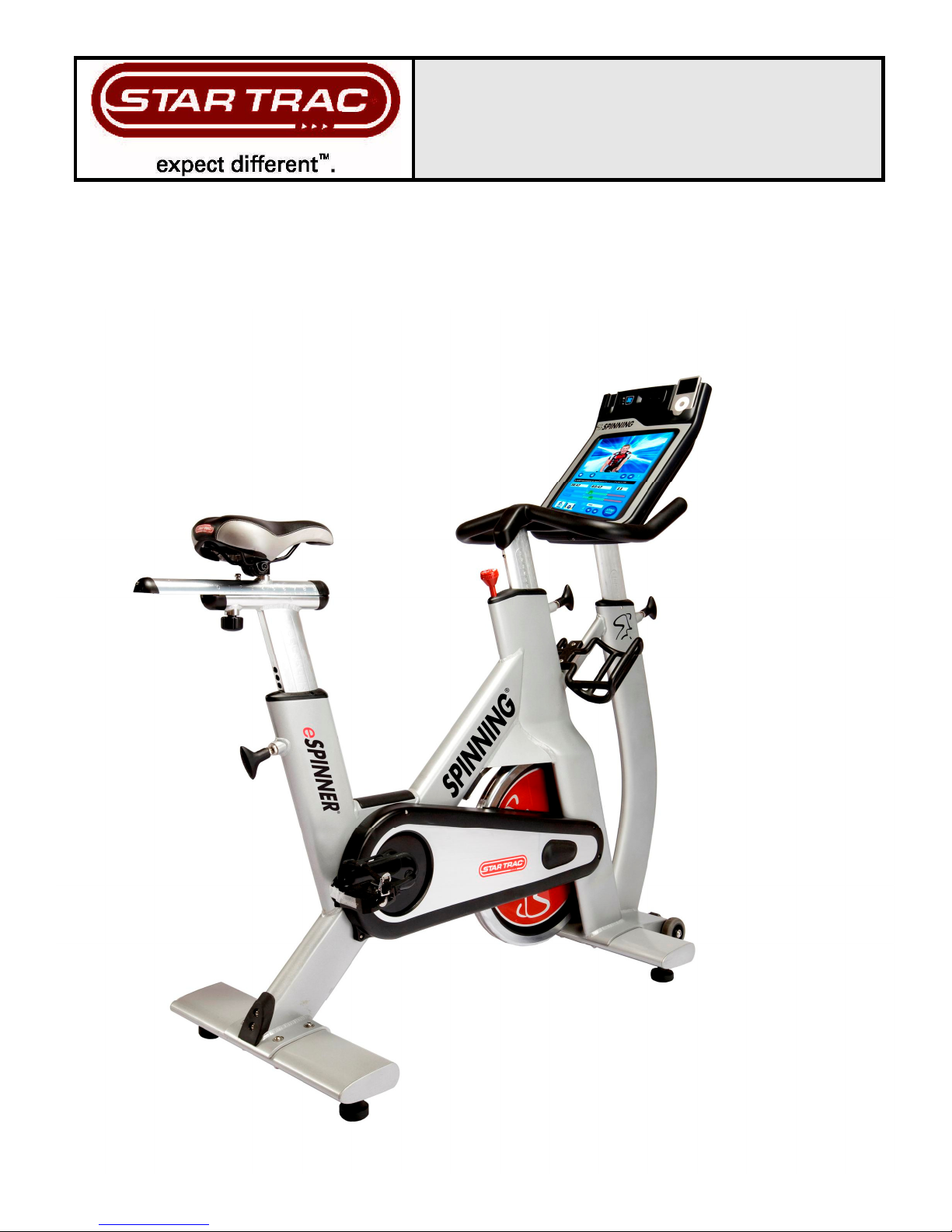
WORK INSTRUCTIONS,
eSPINNER INSTALLATION
2
620-7924 Rev A
Page 3
Before using this product, it is essential to read ALL installation Instructions and this ENTIRE
operations manual; the manual describes equipment setup and instructs members on how to
use it correctly and safely.
TOOLS REQUIRED
GENERAL
1. Open-End Wrench
2. Multi-purpose Wrench
3. 4MM Hex Wrenches
4. 5MM Hex Wrenches
5. 6MM Hex Wrenches
6. Torque Wrench
(Included)
(Included)
(Included)
(Included)
(Included)
(Not Included)
FACTORY CERTIFIED INSTALLER
If you are a Factory Certified Installer you must:
•
Adhere to all torque and assembly specifications.
•
Use a CALIBRATED TORQUE WRENCH with the necessary hex key sockets
•
NOT USE a powered drill, powered driver or powered impact tool for any part of the assembly.
•
Complete the assembly checklist is completed on each Star Trac product.
•
Complete the final programming, functional and cosmetic checklists for each Star Trac product.
Copyright 2008. Star Trac by Unisen, Inc. Star Trac Fitness, Star Trac®, and the Star Trac Logo are registered trademarks of Unisen Inc. All rights
reserved, including those to reproduce this book or parts thereof in any form without first obtaining written permission from Star Trac.
Spin®, Spinner®, Spinning® and the Spinning logo are registered trademarks of Mad Dogg Athletics, Inc.
Smart Release™ is a registered trademark of Nautilus, Inc.
SPD is a registered trademark of Shimano American Corporation.
Every effort has been made to keep this information current; however, periodically, changes are made to the information herein, and these changes
will be incorporated into new editions of this publication. All product names and logos are trademarks of their respective owners. Printed in the USA.
3
620-7924 Rev A
Page 4
UNPACKING INSTRUCTIONS
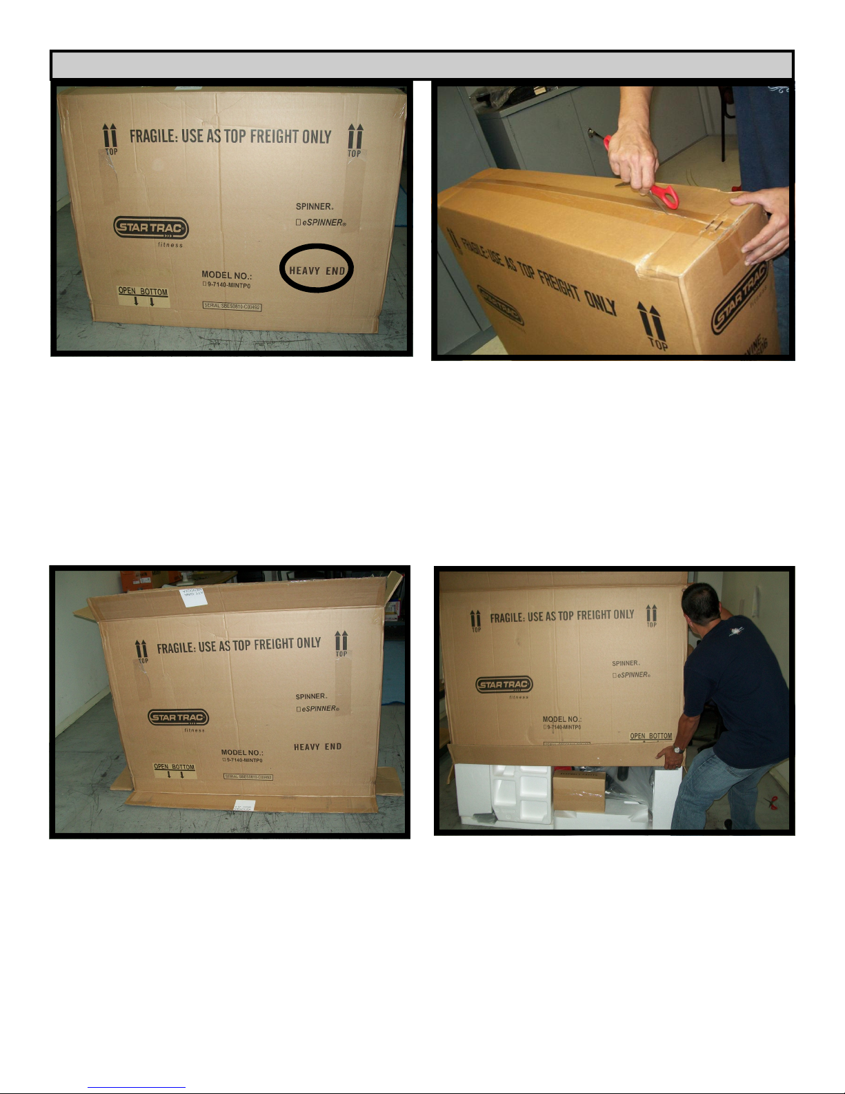
Step 1.
Arrange the assembly area so that the area is free
from objects that could potentially damage the
parts.
When positioning the box verify that the HEAVY
END logo is at the bottom as indicated by the
black oval in the picture.
Step 2.
Open the carton first at the top and bottom. Use
scissors or a knife to cut the tape.
Caution: Be careful not to injure yourself; always
cut away from your body.
Step 3.
Fold back all flaps at the top and at the bottom of
the box.
4
Step 4.
Slide-up the outer carton.
620-7924 Rev A
Page 5
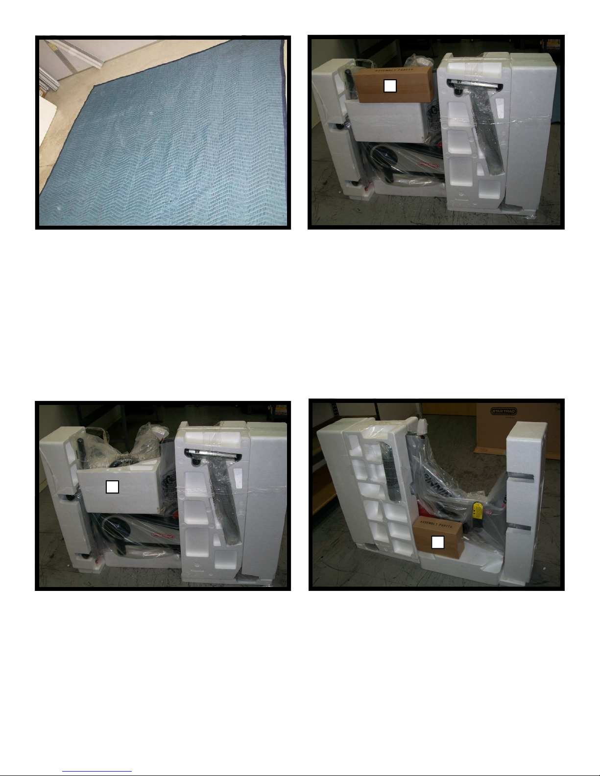
1
Step 5.
Arrange the unpacking area so that the area is
free from objects that could potentially damage
unpacked components.
1
Step 6.
Remove box 1 containing assembly parts.
Step 7.
Remove foam insert 1.
5
2
Step 8.
Remove box 2 containing assembly parts.
620-7924 Rev A
Page 6
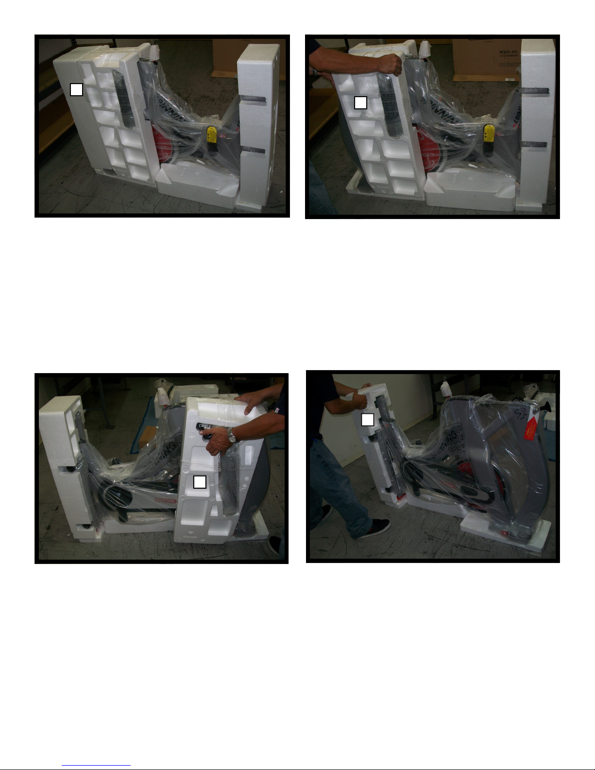
Step 10.
2
Step 9.
Remove foam insert 2.
3
Remove foam insert 3.
Step 11.
Remove foam insert 4.
5
4
Step 12.
Remove foam insert 5.
6
620-7924 Rev A
Page 7
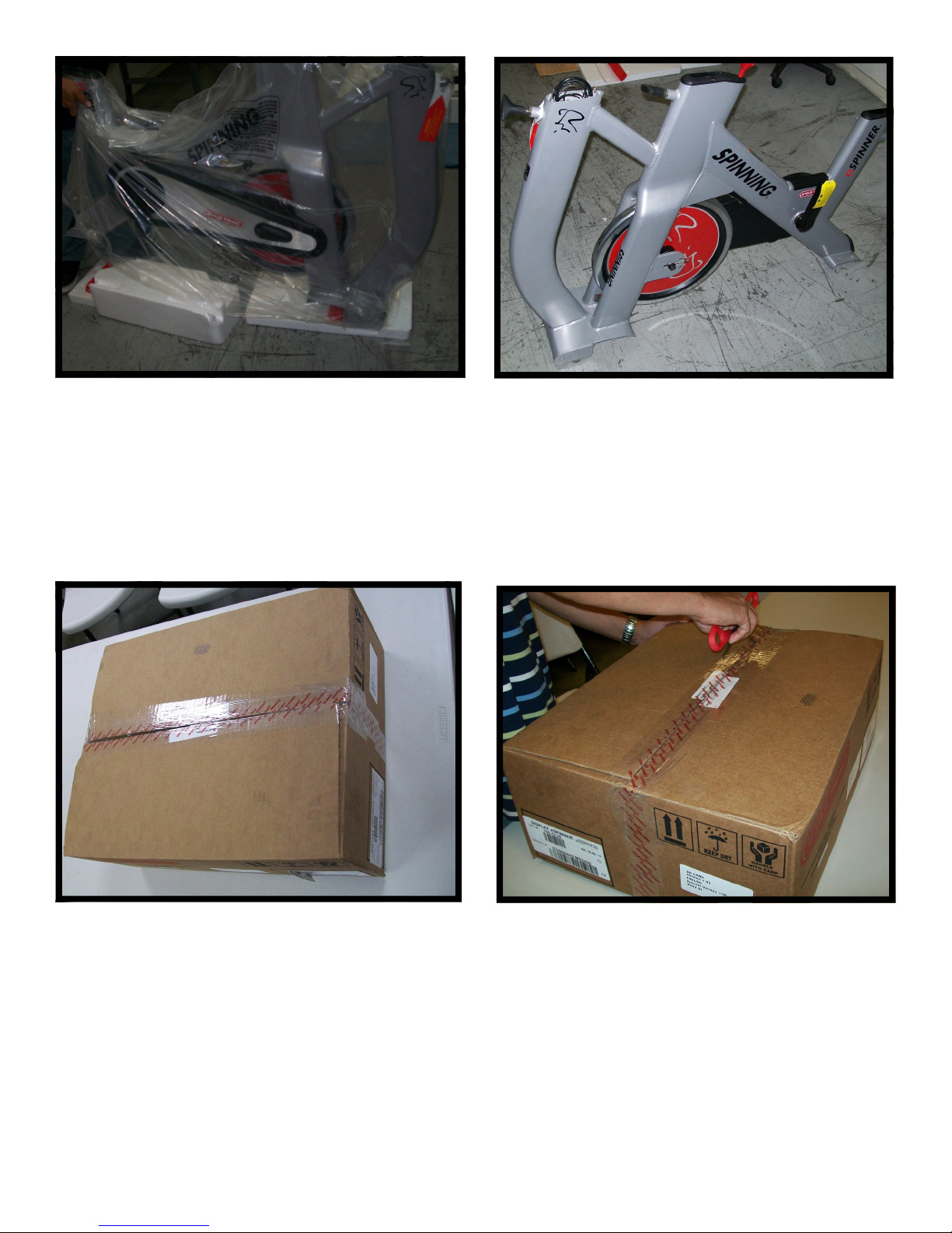
Step 14.
Step 13.
Remove plastic protector.
Position the main frame assembly upright and
verify that the assembly area is free from objects
that could potentially damage the bike.
Step 15.
Locate the Carton containing the console.
Place the carton in an area that is free from objects that could potentially damage the parts .
Step 16.
Use scissors or a knife to cut the tape.
Caution: Be careful not to injure yourself; always cut away from your body.
7
620-7924 Rev A
Page 8
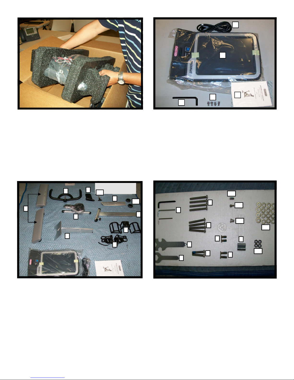
Step 18.
4
1
Step 17.
Remove components from inside the carton and
remove the foam.
2
6
9
8
11
1
4
7
5
10
3
5
2
Verify that Carton 2 Console contains:
1. Main Console
2. Manual
3. 5/16X18X.75” Philips Pan Head Screw X 4
4. Power Cord X 1
5. Hex Wrench “3/16”
12
6
3
3
5
8
2
4
1
13
14
10
9
7
11
Step 19.
Verify that shipment inside the main Carton contains:
1. Handlebar Post X 1
2. Handlebar w/Grip X 1
3. Seat Post X 1
4. Seat Slider Assembly w/ Saddle X 1
5. Pedals (set of two) X 1
6. Leg Assembly X 2
7. Water Bottle Holder X 1
8. Console Post Plastic Sleeve X 1
9. Console Post X 1
10. Transport Wheels X 2
11. Rear Pop Pin X 1
Step 20.
Verify that shipment inside the main Carton contains the hardware
listed below:
1. Open End Wrench X 1
2. Multi Wrench X 1
3. Hex Wrench (5mm, 4mm, and 3mm) X 3
4. M10X1.5,45 Button Head Screw X 2
5. M10X1.5, 60mm Button Head Screw X 4
6. M10X1.5, 65mm Button Head Screw X 4
7. M8X1.25, 20mm Flat Head Screw X 2
8. M8X1.25, 16mm Flat Head Screw X 2
9. Spacer 30mm X 2
10. 20mm Washer Flat X 16
11. M10X1.5 Nyloc Hex Nut X 4
12. M8X1.25, 16mm Socket Set Screw X 1
13. M6X1.0X15mm Hex Bolt X 1
14. M4X1.0X10mm Phillips Pan Head Screw X 2
8
620-7924 Rev A
Page 9
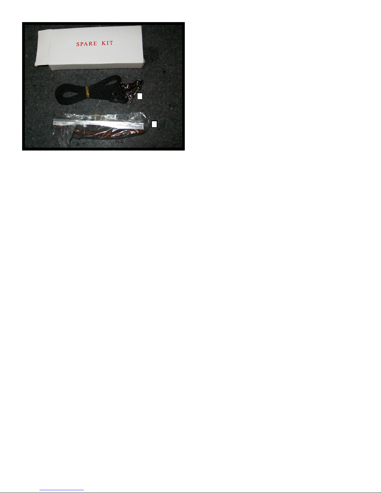
Step 21.
Verify that the Spare Kit contains:
1. Pedal strap
2. Spare Brake Pad
1
2
9
620-7924 Rev A
Page 10
ASSEMBLY INSTRUCTIONS
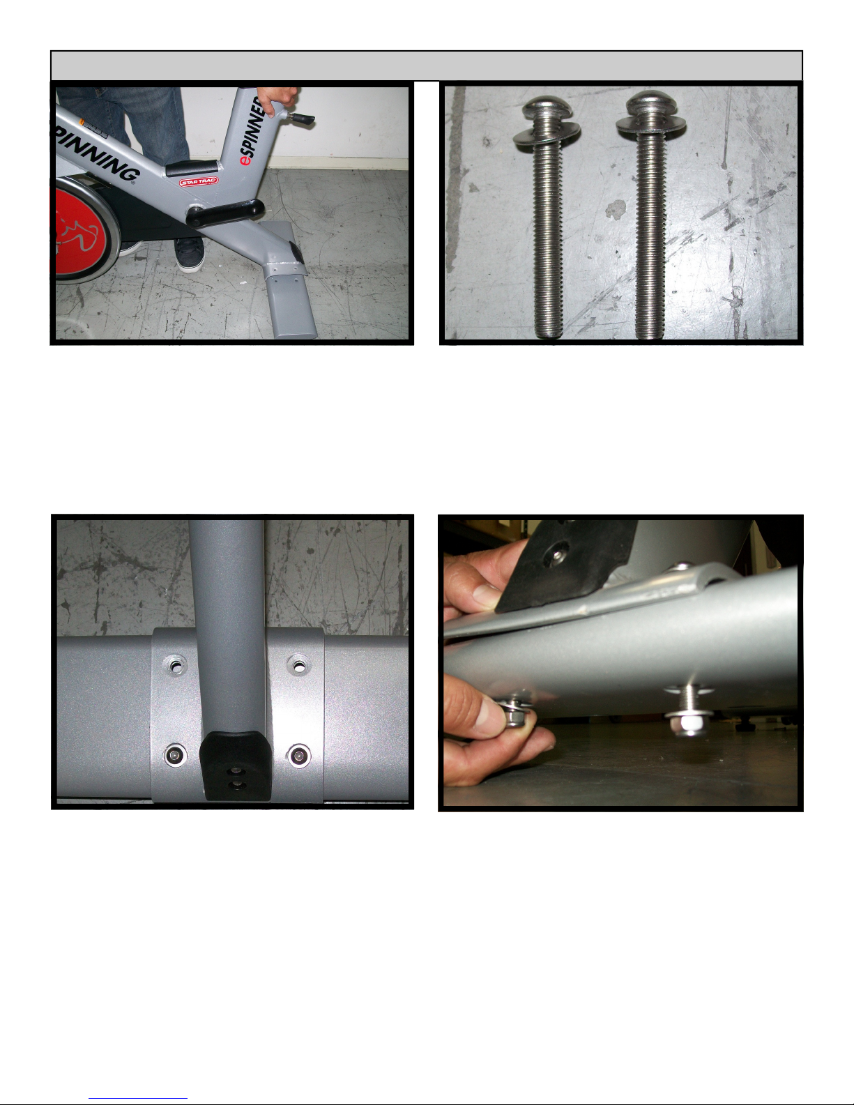
Step 22.
Locate the Rear Leg Assembly in the mating position under the frame.
Step 23.
Locate (2) M10X60mm Button Head Screws. Preinstall a 10mm Flat Washer onto each Button
Head Screw.
Step 24.
Secure the Rear Leg Assembly to the frame using
(2) M10X55mm Button Head Screws with 10mm
Flat Washers.
10
Step 25.
Hand-install (1) Flat Washer and then (1)
M10X1.5 Nyloc Hex Nut onto each Button Head
Screw.
620-7924 Rev A
Page 11
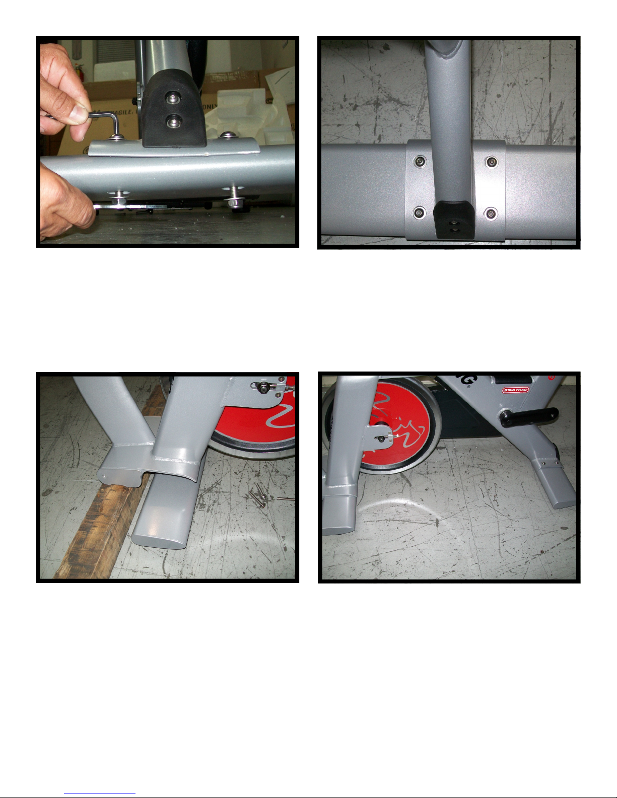
Step 27.
Step 26.
Utilizing a 5mm Hex Wrench and a Multi Wrench
tighten the nuts onto the screws.
Note: Utilize a torque wrench to tighten all hardware to 85 lbs-in.
Repeat steps 23 through 26 using (2)
M10X1.5X65mm Button Head Screws, for the two
forward mounting locations.
Note: Utilize a torque wrench to tighten all hardware to 85 lbs-in.
Step 28.
Let one assembler lift up the front of the bike or
suspend the front of the bike by wedging a block.
Step 29.
Locate the Front Leg Assembly in mating position
under the frame. Verify that the front and rear leg
assemblies are parallel.
11
620-7924 Rev A
Page 12
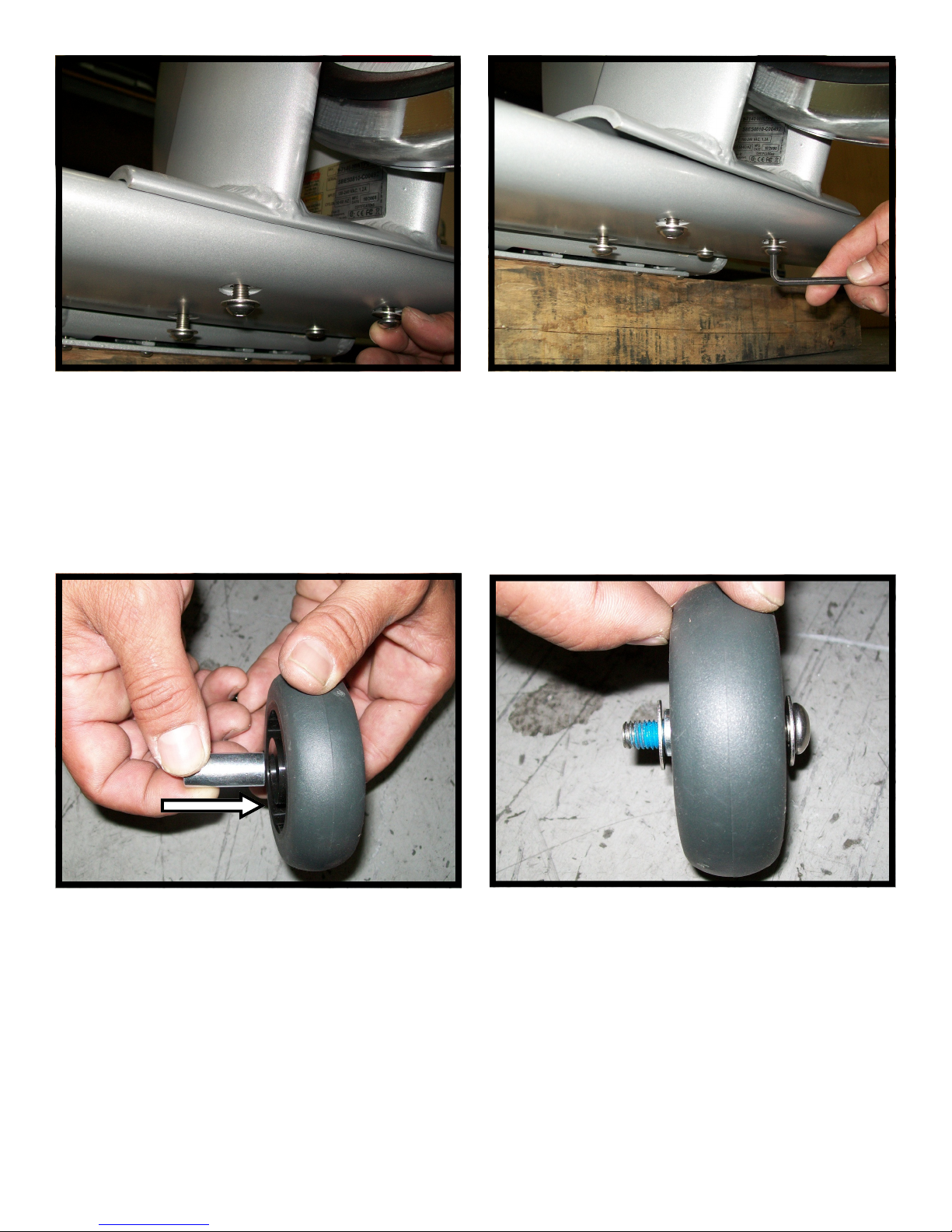
Step 31.
Step 30.
Hand-install (2) M10X1.5X60mm Button Head
Screws each through (1) 20mm Flat Washer in
the rear mounting holes to secure the Front Leg
Assembly to the Frame.
Hand-install (2) M10X1.5X65mm Button Head
Screws each through (1) 20mm Flat Washer in
the forward mounting holes to secure the Front
Leg Assembly to the Frame.
Utilizing a 5mm Hex Wrench tighten all Button
Head Screws.
Note: Utilize a torque wrench to tighten all
screws to 85 lbs-in.
Step 32.
Locate (1) 30mm Spacer and install it into the
mating hole on the Transport Wheel.
Step 33.
With (1) 20mm Flat Washer positioned on opposite sides of the Transport Wheel insert (1)
M10X1.5X45mm Button Head Screw into the
Transport Wheel.
12
620-7924 Rev A
Page 13
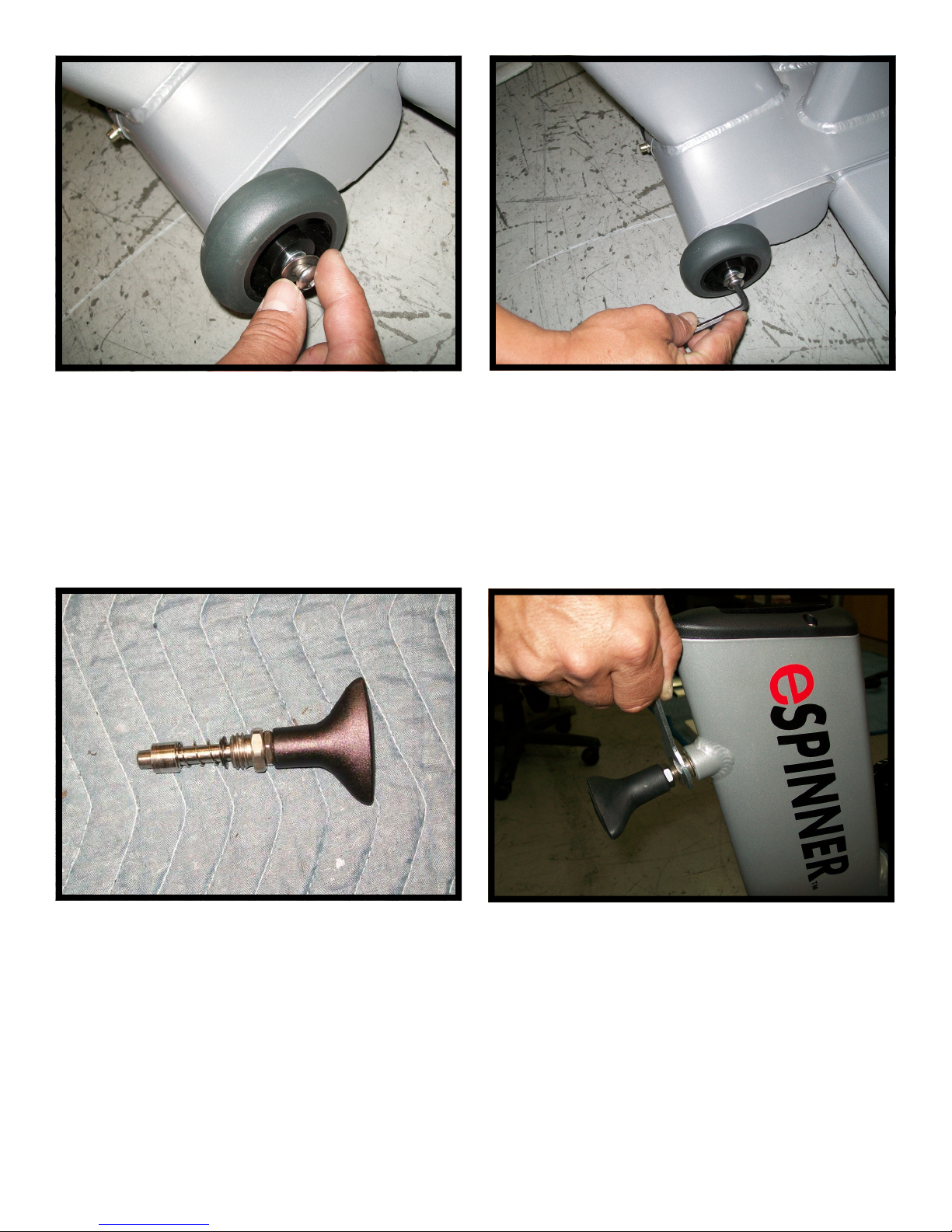
Step 37.
Step 34.
Hand-install the M10X1.5X45mm Button Head
Screw into the mating hole on the Frame.
Note: Utilize a torque wrench to tighten screws to
85 lbs-in.
Step 35.
Utilizing a 5mm Hex Wrench secure the
M10X1.5X45mm Button Head Screw onto the
Frame. Repeat steps 32 through 35 to install the
second Transport Wheel to the right side of the
Frame.
Step 36.
Grab the rear Pop Pin.
Utilizing an Open End Wrench secure the Pop Pin
to the Frame.
Note: Verify that the Pop pin is tightened to 50
lbs-in torque value.
13
620-7924 Rev A
Page 14
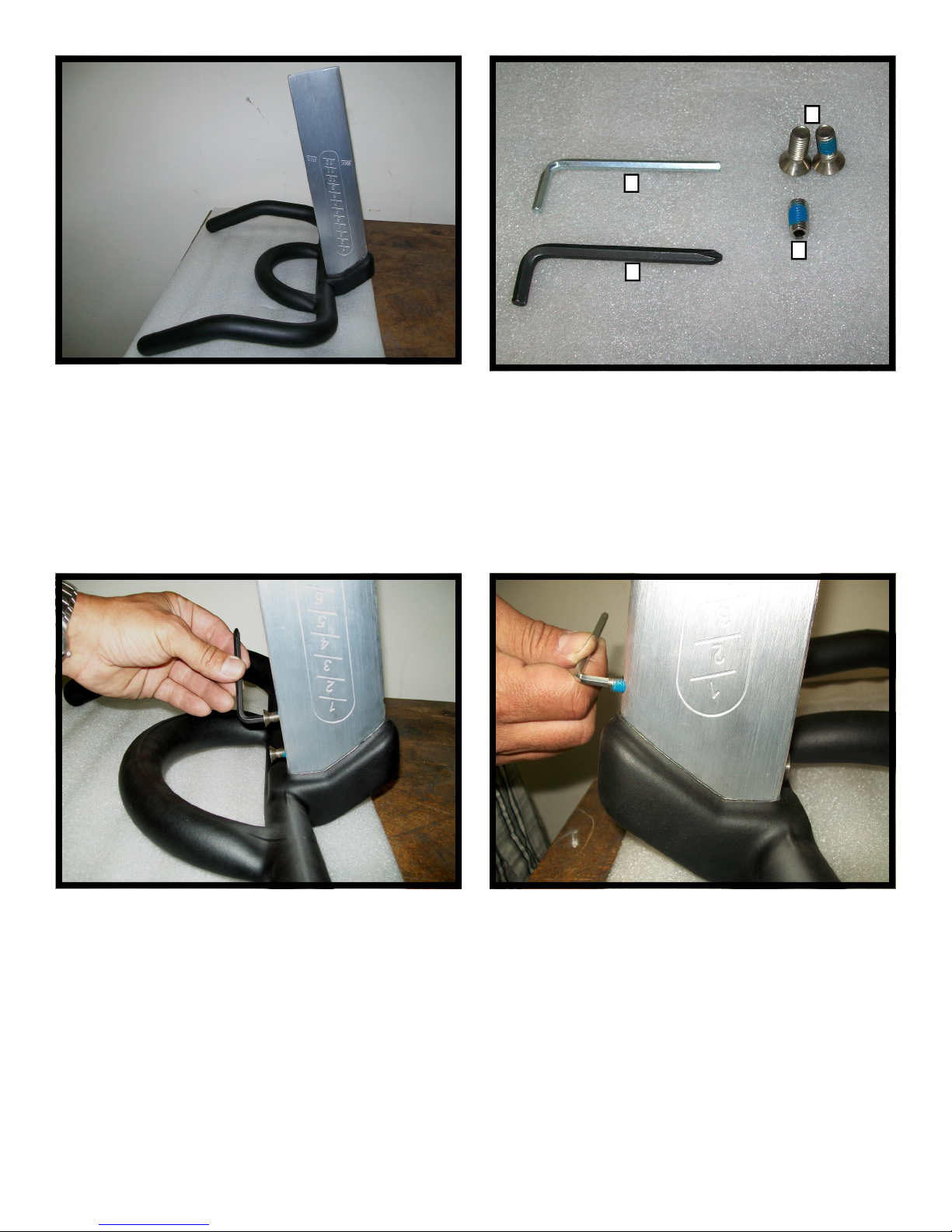
4
2
3
1
Step 38.
Grab the Handlebar Post and install it onto Handlebar.
Step 39.
Locate the parts listed below:
1. 5mm Hex Wrench X 1
2. 4mm Hex Wrench X 1
3. M8X1.25, 16mm Flat Head Screw X 2
4. M8X1.25, 16mm Socket Set Screw X 1
Step 40.
Align the mating holes and hand-thread (2)
M8X1.25, 16mm Flat Head Screws then, utilizing
a 5mm Hex Wrench tighten the screws.
Note: Tighten both screws to 60 lbs-in.
14
Step 41.
Utilizing the 4mm Hex Wrench tighten the
M8X1.25, 16mm Socket Set Screw.
Note: Tighten the set screw to 60 lbs-in.
620-7924 Rev A
Page 15
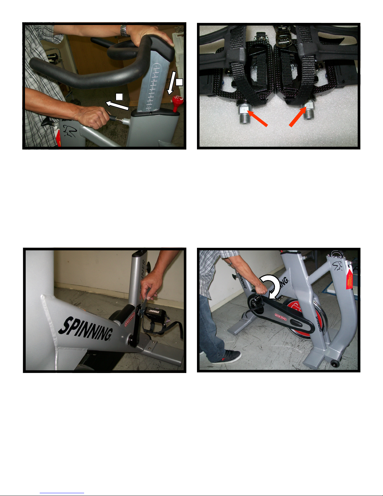
2
1
Step 42.
1. Loosen the Pop Pin and pull Pop Pin away from
Handlebar Post Frame.
2. Insert Handlebar Post into Frame Handlebar
Post.
Step 43.
Grab the set of pedals. The right pedal shaft is
marked by letter R and the left pedal shaft is
marked by the letter L.
Note: Take care when installing the pedals to
avoid threading pedal spindles to the wrong
side of the bike and cause damage to the
pedals and the cranks.
Step 44.
Hand-thread the Left Pedal and then Utilize a
Multi Wrench to install the left pedal to the leftside crank arm by turning the pedal spindle in the
counter clockwise direction.
15
Step 45.
Hand-install the Right Pedal and then utilize a
Multi Wrench to install the right pedal to the rightside crank arm by turning the pedal spindle in the
clockwise direction.
620-7924 Rev A
Page 16
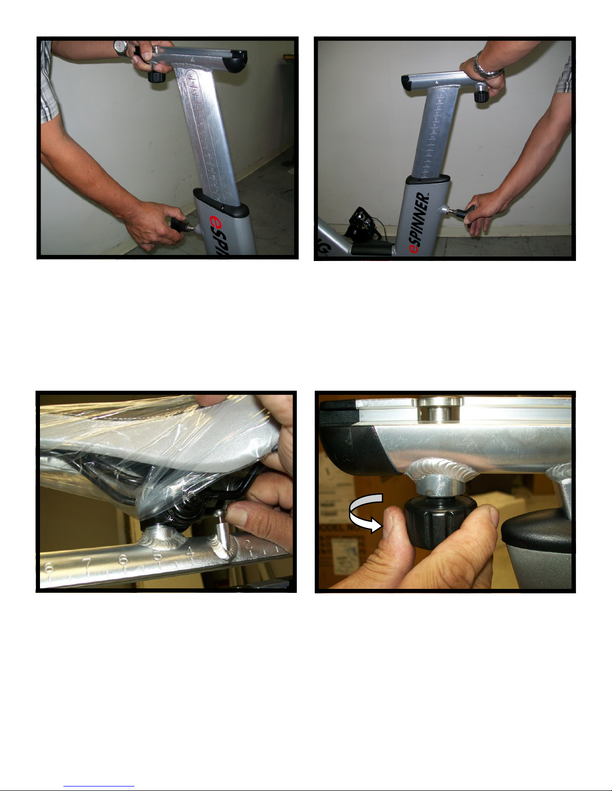
Step 46.
1. Loosen the Pop Pin and then pull it away from
the frame Seat Post.
2. Install Seat Post into Frame Seat Post.
Step 47.
1. Lower Seat Post to the lowest level.
2. Let Pop Pin engage the mating hole on the
Seat Post.
3. Tighten the Pop Pin.
Step 48.
Locate the Seat. Make sure the locking pin moves
freely by pulling it up and then releasing it.
(The locking pin is spring loaded)
16
Step 49.
Align the Slider Clamp with the Guide Rail by
turning the Seat Slider Knob.
620-7924 Rev A
Page 17
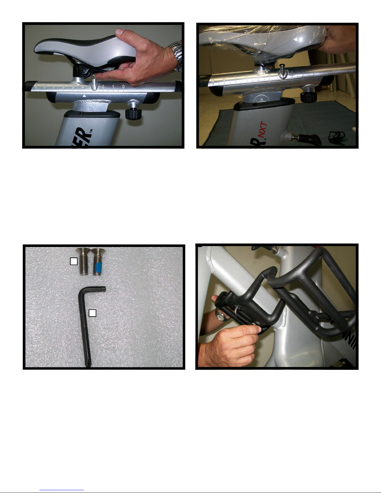
Step 50.
Pull the locking pin up while moving Seat Slider
into position.
2
1
Step 51.
When indicator (highlighted by the left side arrow)
points to a value within the 0 and 9 range release
the pin as highlighted by the right side arrow.
Step 52.
Locate the tool and parts listed below:
1. 5mm Hex Wrench X 1
2. M10X1.5, 25 Flat Head Screw X 2
17
Step 53.
Locate the Water Bottle Holder. Utilizing a 5mm Hex
Wrench and (1) M10X1.5, 25 Flat Head Screw install
Water Bottle Holder under the support cross bar onto
the frame. Next, Secure Water Bottle Holder onto frame
using the second screw. Use the Hex Wrench to verify
that both screws are tightened.
Note: Verify that both screws all tightened to 85
lbs-in.
620-7924 Rev A
Page 18
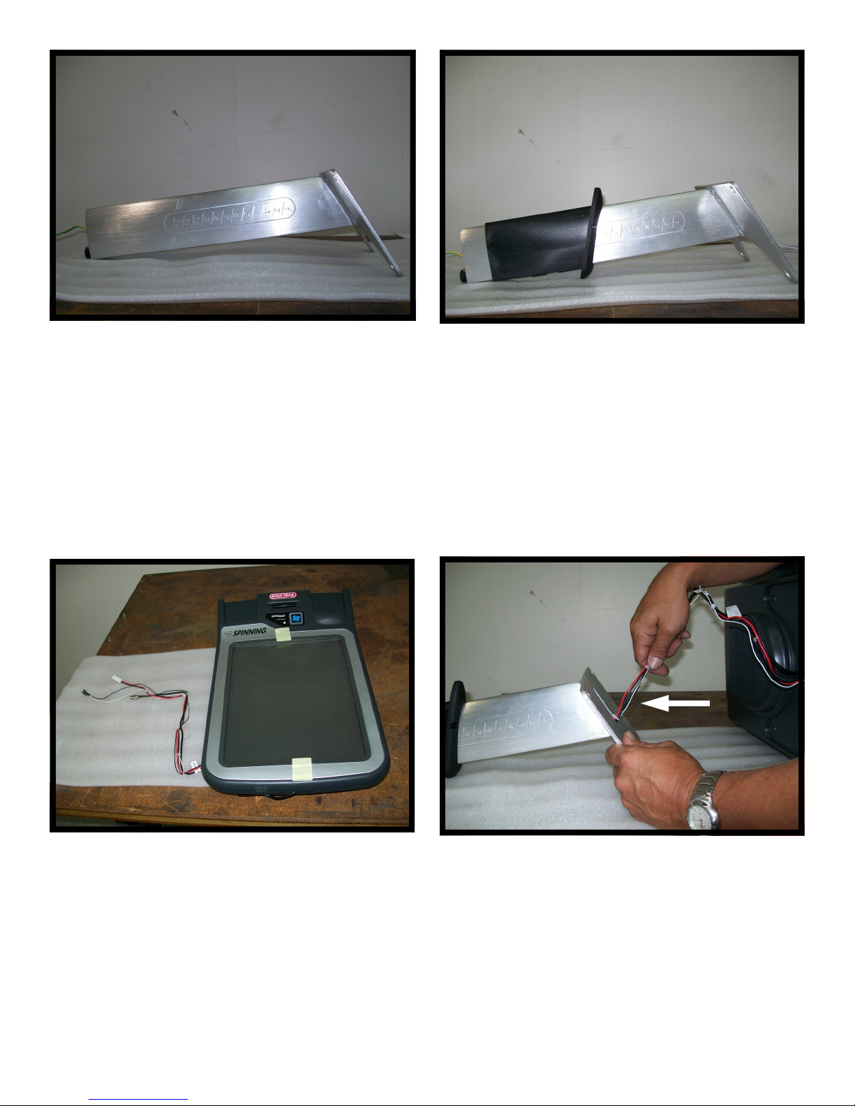
Step 54.
Locate the Console Support Tube.
Step 55.
Install Console Support Sleeve onto Console Support Tube.
Step 56.
Grab the console and locate the 3 cords from the
back of the console.
18
Step 57.
Note: It is necessary to utilize two installers
in order to successfully perform the following assembly steps.
While one installer is securing the console the
second installer routes the three cords from the
back of the console inside the Console Support
Tube.
620-7924 Rev A
Page 19
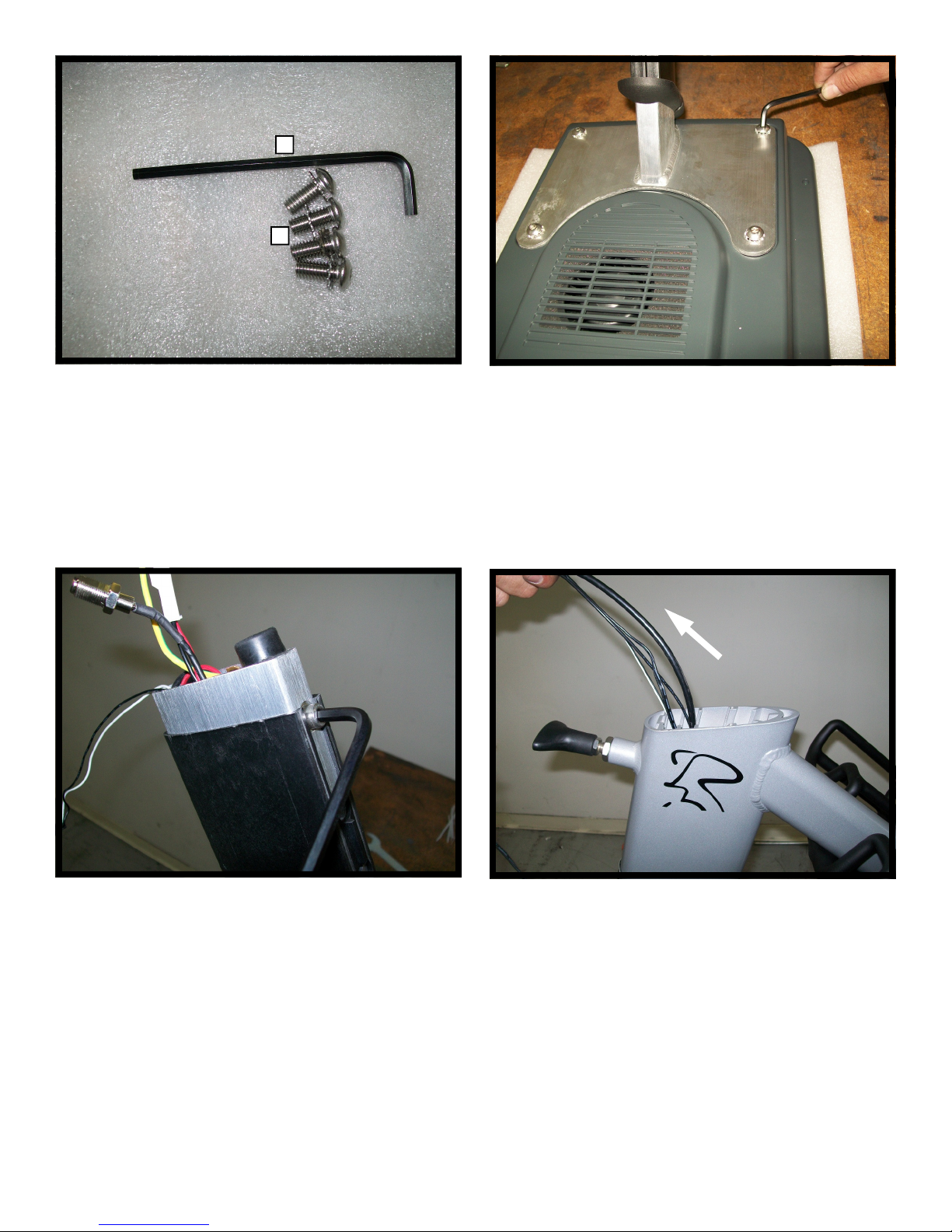
1
2
Step 58.
Locate the tool and parts listed below:
1. 3/16 Allen Wrench X 1
2. 5/16 X 18 Pan Head Screws X 4
Step 59.
While taking adequate care so that the cords will
not be trapped or pinched between the Console
Tube Plate and the Console, align the Console
Plate to the Console. Next, secure Console Tube
Plate to the Console using the 3/16 Allen Wrench
and (4) 5/16 X 18 Pan Head Screws.
Note: Verify that all screws are tightened to 25
lbs-in.
Step 60.
Utilizing a 5mm Hex Wrench install (1) M6 X 1.0 X
15mm Hex Bolt into the mating hole at the bottom of Console Support Tube.
Note: Verify that the bolt is tightened to 25 lbsin.
19
Step 61.
Gently lift up mating wires from inside the Frame
Console Tube.
620-7924 Rev A
Page 20

Step 62.
Grab the coax cable coming from the Frame end
and the coax cable coming from the Console Support Tube end. Hand-install the male and female
connectors finger tight.
Step 63.
Utilize a 7/16” Open Wrench to hold the connector
on the Console Support Tube side while using the
second 7/16” Open Wrench to turn the other connector a quarter turn.
Step 64.
Plug the connector pair from the Console end to
the mating connectors from the frame end. Verify
that all connectors are adequately locked.
20
Step 65.
Connect the ground wire from the Console end to
the ground wire from the Frame end.
620-7924 Rev A
Page 21
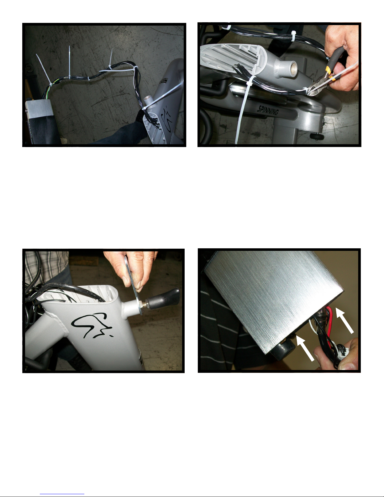
Step 66.
Utilize (6) tie straps to adequately harness the
wires.
Step 67.
Using a cutter, cut and remove the unused portion of tie straps.
Step 68.
Use an Open End Wrench to temporarily remove
the Pop Pin installed to the Frame Console Post.
21
Step 69.
Manage the wires on the Console Post end by inserting the bundle of cords inside the Console
Post.
Note: Take proper care not to damage cords.
620-7924 Rev A
Page 22
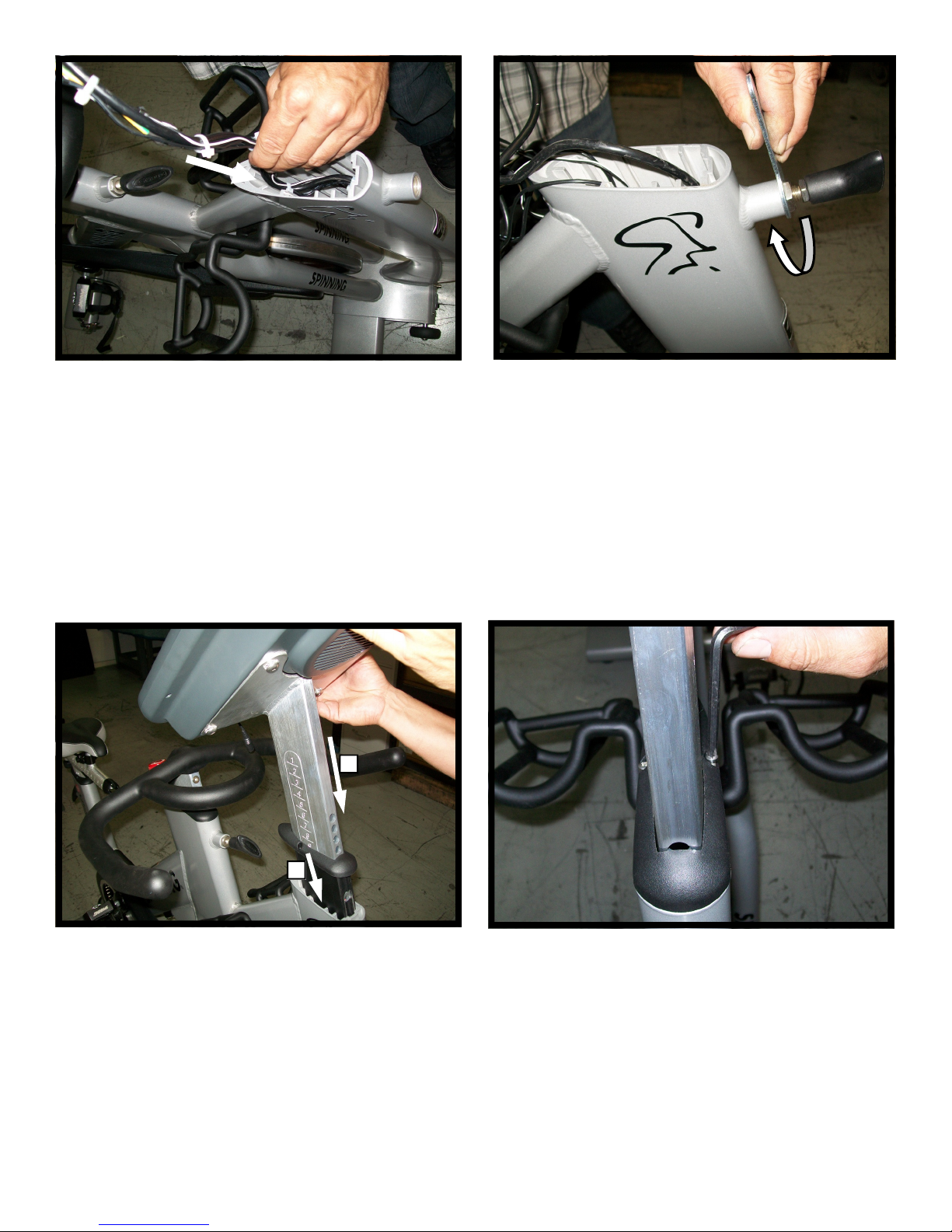
Step 70.
Manage the wires on the Frame end by inserting
the bundle of cords inside the Frame.
Note: Take proper care not to damage cords.
1
Step 71.
Reinstall Pop Pin into the Frame Console Post.
2
Step 72.
1. Insert Console Post into the Frame Console
Post.
2. Push the Console Support Sleeve all the way
down into the Frame Console Post.
22
Step 73.
Utilizing (2) M4 X 1.0 X 10mm Phillips Pan Head
Screws and a Phillips Head Screw Driver secure
the Console Support Sleeve to the Frame.
Step 74.
Now, Slowly lower console until pop pin engages.
620-7924 Rev A
Page 23

FUNCTIONAL TEST
2
1
Step 75.
Verify that the bike is placed on a flat surface.
Next, adequately stabilize the bike by adjusting
leveling feet.
1
2
Step 76.
1. Loosen the Pop Pin.
2. Lift the Seat Post all the way up and verify
that the Pop Pin engages mating holes each
time you raise the Seat Post one level higher.
Step 77.
1. Lower the Seat Post all the way down
2. Release and tighten the Pop Pin.
23
Step 78.
Secure the Seat Slider Post Assembly in place by
turning the Seat Slider Lock Knob.
620-7924 Rev A
Page 24
1
2
1
2
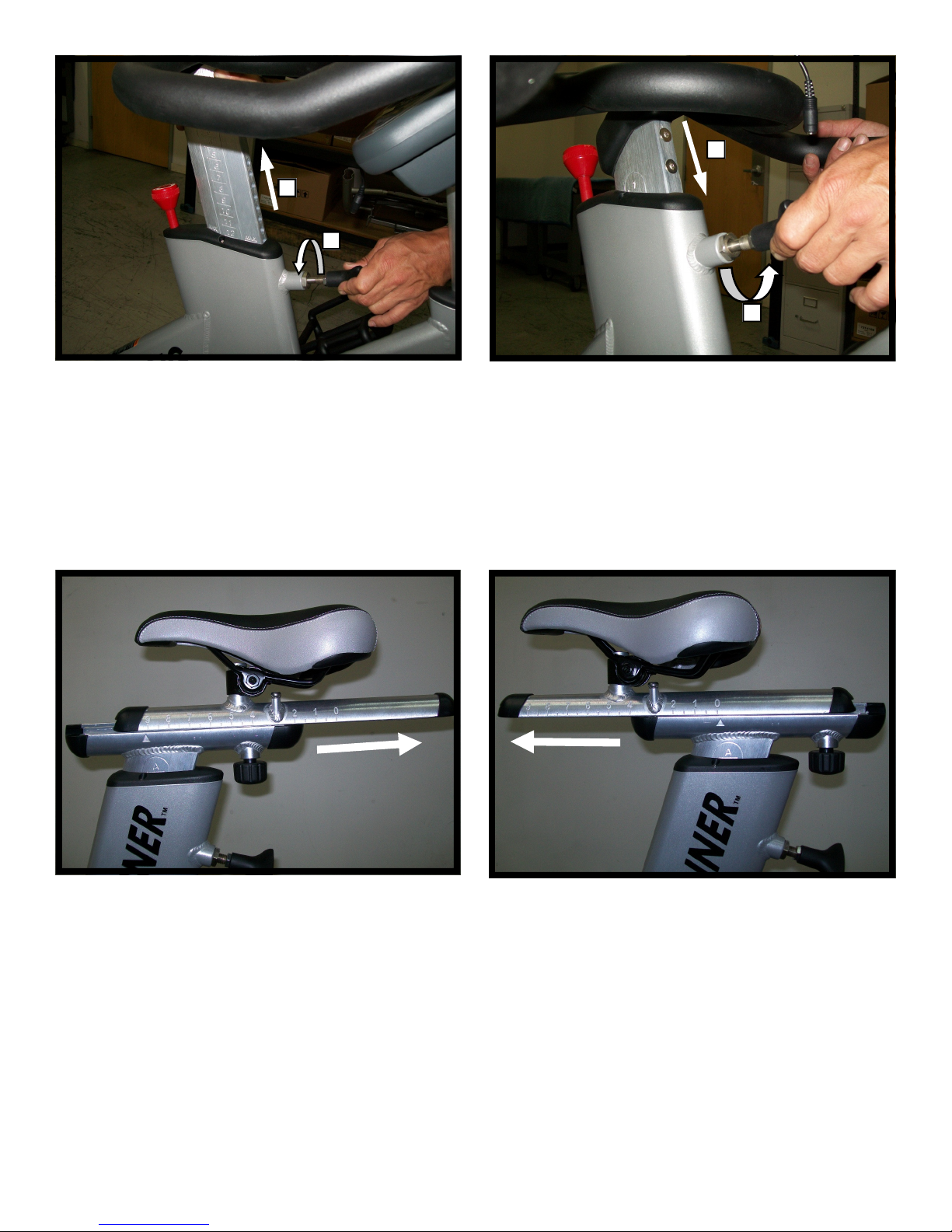
Step 79.
1. Loosen the Pop Pin and pull it away from the
frame.
2. Lift the Handlebar Post all the way up and verify that the Pop Pin engages the corresponding
mating hole each time you raise the Seat Post
one level higher.
Step 80.
1. Lower Handlebar Post all the way down and
allow Pop Pin engage the corresponding mating hole on the Handlebar Post.
2. Tighten Pop Pin.
Step 81.
Verify that the Seat Slide travels all the way back
for the indicator to point at level 9.
24
Step 82.
Verify that the Seat Slide travels all the way forward for the indicator to point at level 0.
620-7924 Rev A
Page 25
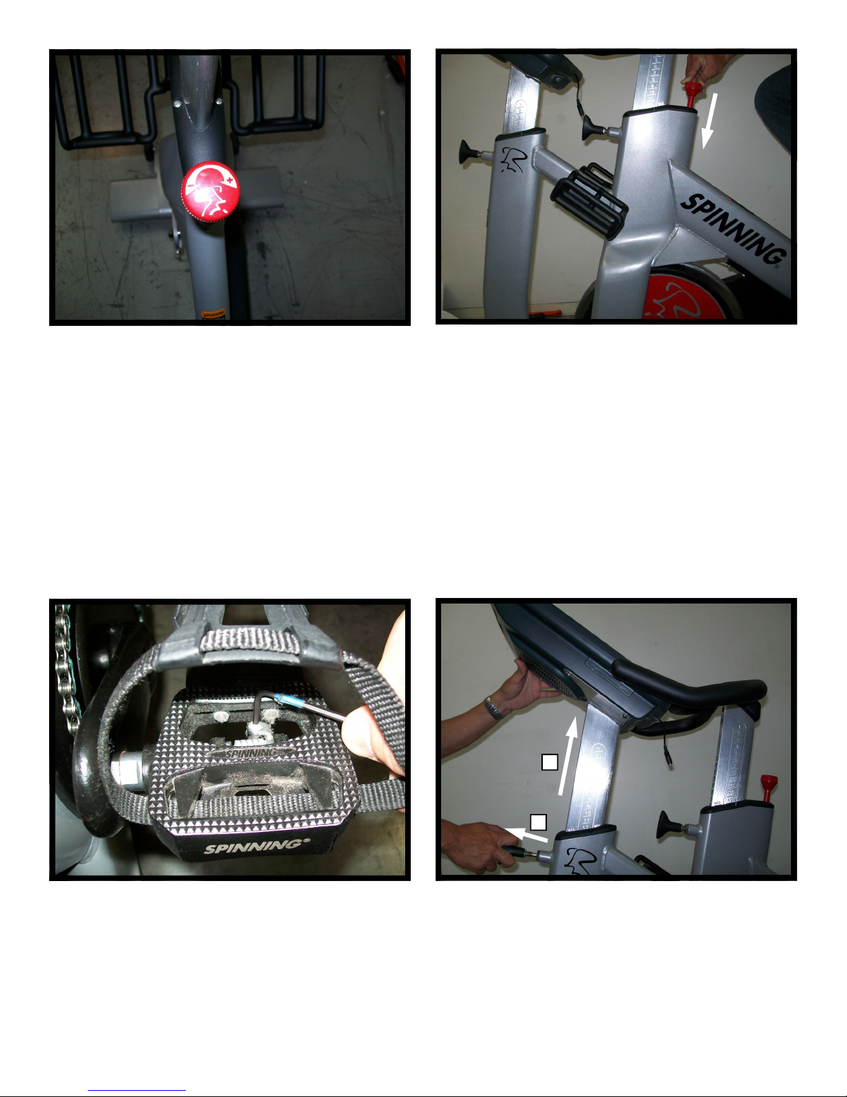
Step 83.
Test bike operation.
•Mount the bike.
• Turn Resistance Knob in the counterclockwise
direction to reduce brake resistance as
indicated by the “-” sign.
• Start pedaling when resistance is low.
• Verify that pedaling is smooth and that there is
no excessive noise or wobble.
• Increase the resistance by turning knob in the
clockwise direction and verify that it changes
accordingly. Confirm there is no excessive
noise or wobble.
• Decrease the resistance and verify that it
changes accordingly.
Step 84.
Push down the Resistance Knob (brake) to ensure
that Flywheel stops abruptly
.
Step 85.
Utilizing a 3mm Hex Wrench turn the adjustment
screw to ensure the bike shoe engages the SPD
pedal appropriately.
25
2
1
Step 86.
1. Loosen the Pop Pin and pull it away from the
frame.
2. Lift Console Post all the way up and verify that
the Pop Pin engages the corresponding mating
hole each time you raise the Console Post.
620-7924 Rev A
Page 26
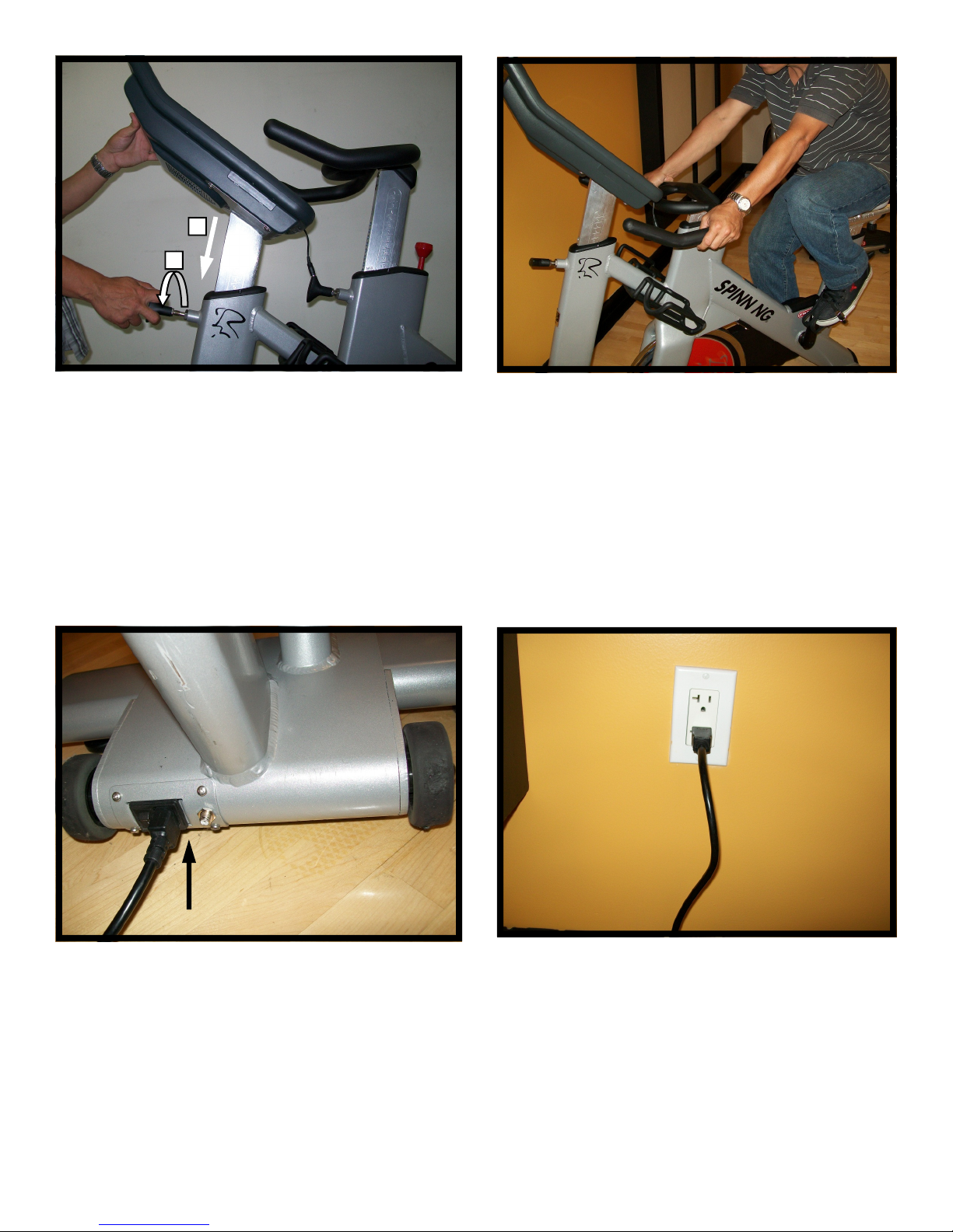
1
2
Step 87.
1. Lower the Console Post all the way down.
2. Allow Pop Pin engage the corresponding mating hole on the Console Post. Tighten Pop Pin.
Step 88.
Check the bike for steadiness.
Step 89.
Plug the Power Cord to the IEC connector.
26
Step 90.
Plug the Power Cord to the corresponding power
outlet.
620-7924 Rev A
Page 27
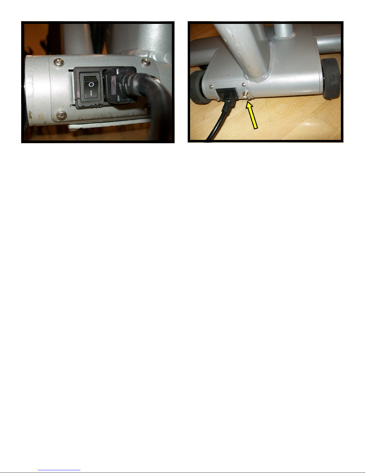
Step 91.
Turn the switch on. And Visually inspect the unit.
Step 92.
If connecting TV, install coax cable and tighten
with 7/16 wrench.
Note: For all questions regarding Calibration and
other settings please refer to the User’s Manual.
27
620-7924 Rev A
Page 28
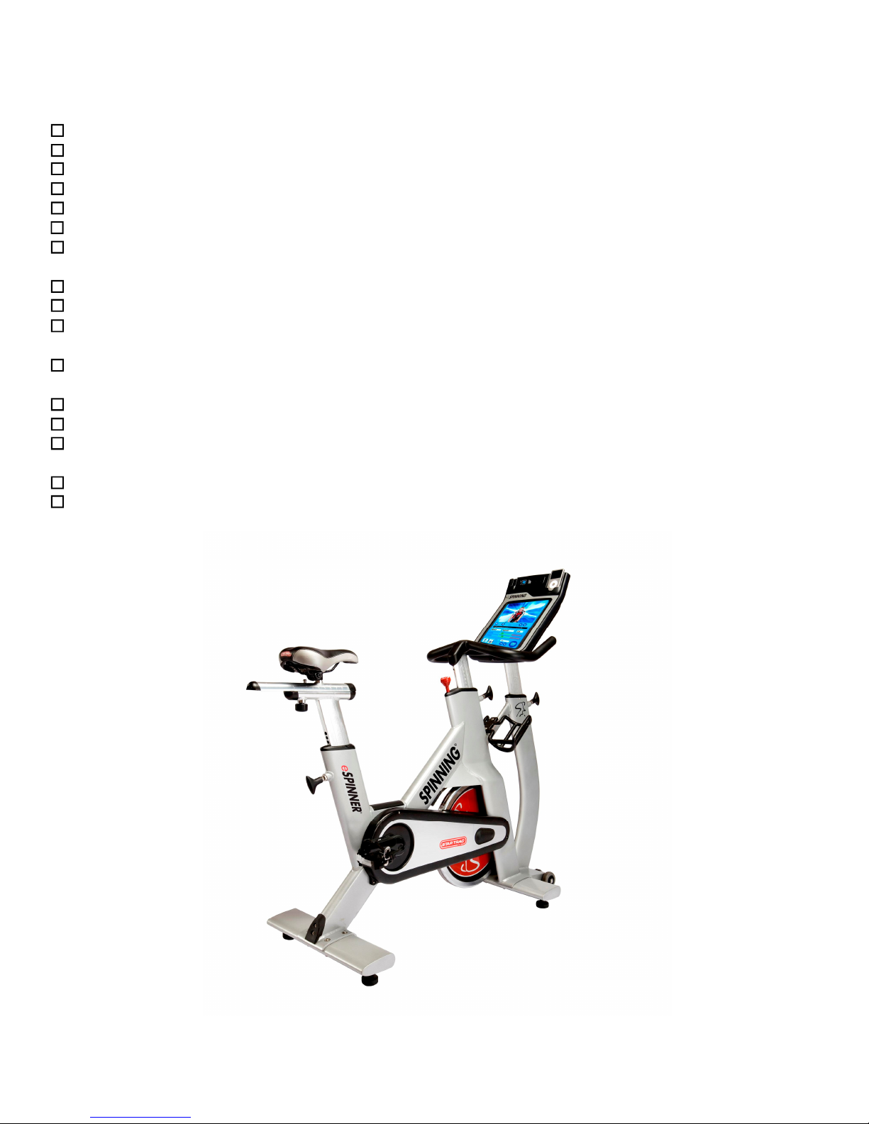
Use the checklist below to ensure the proper installation of the bike
1. Rear and front leg assemblies are properly installed and secured.
2. Handlebar post moves freely and can be locked in all levels.
3. Seat Post moves freely and can be locked in all levels.
4. Console Post moves freely and can be locked in all levels.
5. All screws are tightened and torqued down to the specified torque value.
6. Pop pins are secured and freely engage and disengage mating holes.
7. Seat slide is properly installed and slides along the entire travel range freely. Seat Slide can
be locked in all levels.
8. Right and left pedals are properly installed.
9. Resistance knob operates properly and when applied flywheel stops abruptly.
10. It takes approximately 80 seconds for the Console to boot into the e-Spinner application after
the switch is turned to the ON position.
11. Touch screen responds to commands as specified in the User’s Manual section regarding the
Calibration and Setup.
12. Video workouts operate and headphones output proper audio to both sides of headphones.
13. iPod test: Verify iPod menu is functioning and user can browse and listen to music and videos
14. TV is setup properly per the owner’s manual, signal is clear and audio is coming from both
headphones.
15. Using a chest strap or wireless heart rate simulator, verify heart rate is recording properly.
16. While computer is running, test ride a workout to verify cadence is picking up properly.
For technical assistance call Star Trac Customer Service: 1 800 503 1221
28
620-7924 Rev A
Page 29

Telephone: (800) 228-6635, (714) 669-1660
29
STAR TRAC
14410 Myford Road
Irvine, California 92606
Fax: (714) 508-3303
http://www.startrac.com
620-7924 Rev A
 Loading...