

Page 1
8TR/8TRx InsTallaTIon InsTRucTIons
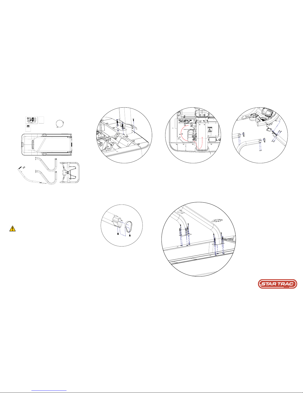
2. Install the Mast
Remove the Neck Grommet and Motor Shroud Cap
and set aside. Be careful to not damaged data cable.
Remove the Motor Shroud then the Front Motor Shroud
Cap from the unit.
Insert mast as shown and fasten with (2) 5/16-18 x 3.0”
and (2) 5/16-18 x 1.0” socket head cap screws, (4) 5/16
washers and (4) lock washers. Do not fully tighten.
3. Rout Cables thRough Mast
Route all cables up through the lower neck out out
of the top of the neck. Connect the following wires to
the MCB using the path shown under the elevation
motor:
715-3678 (DC Supply Power Cable) to J20
715-3682 (C-Safe Cable) to J10
715-3781 (Main Interface Ribbon Cable) to J1
4. Mount the DIsplay RaIl
Install the neck beauty ring onto the top of the lower
neck as shown in detail.
Use a 1/4” Hex Allen key to install the four (4) M8x16mm button head cap screws and four (4) 5/16” washers as shown to secure the display rail to the lower
neck. Do not fully tighten and take care when routing
cables to avoid crimping or pinching.
5. Install hanDlebaR
Insert the handrail beauty rings onto the left and right handrails
as shown in step 4. Cut in ring must be oriented as shown above
facing mast. Prior to connecting display rail, slide both side rail
covers onto siderails.
Insert the left and right handrails into the display rail then thread
four (4) 1/4”x3/8” screws into the handrails . Tighten the handrail
hardware only after display rail is connected to both mast and
handrails.
6. seCuRe sIDe RaIls to FRaMe
Position the left and right handrails and use the
three (3) 5/16-18 x 1.0” socket head screws
and three (3) 5/16 washers to secure the handrails to the frame. Start screws only.
Ensure that the neck, handrails, and display
rail are properly aligned then tighten the hardware securing the handrails to the display rail,
the hardware securing the handrails to the
frame, and the lower neck to the frame to the
torque specications below:
Lower Mast to Frame
5/16-18 x 3.0” Socket Head screws
240in-lbs / 27 N·m
Handrails to Frame
5/16-18 x 1.0” Socket Head screws
240in-lbs / 27 N·m
Handrails to display rail
1/4”x3/8” Button Head Socket screws
35in-lbs / 4.0 N·m
For installation assistance or missing parts, please call Startrac Support at 1-800-503-1221
Document #620-8379 - Revision A
1. ReMove all paRts FRoM the box
Remove all the packaging material so the treadmill is ready for
assembly on the shipping crate platform. The raised front of the
shipping crate platform can be removed so that the treadmill can
roll out of the raised shipping platform rather than having to be
lifted out.
With a helper, roll the treadmill frame assembly motor end rst
from the shipping crate platform and place it in the location where
it will be used. Make sure the unit is placed near a power outlet.
Caution: The motor shroud end of the frame assembly is
very heavy and two people may be needed to lift this end
when moving the frame assembly.
Page 2

7. Install MotoR shRouD
Reinstall Front Motor Shroud Cap then fasten Motor Shroud and Side Bed Covers with (6) #10 Truss
Head screws.
8. ReInstall shRouD Cap
Reinstall Motor Shroud Cap and Neck Grommet as
shown
9. valIDate asseMbly
Frame assembly is complete. Prior to mounting console, verify console rail is secure and all mast screws
are present.
10. Install DIsplay ReaR housIng
Fasten the back half of the console assembly to the
display rail using the screws supplied with the console.
11. ConneCt Cables to Console boaRD
Connect the appropriate wires coming out of the
mast to the correct locations, please reference the
console wiring guide (Doc 620-8387) contained in
the console box.
12. seCuRe DIsplay
Secure the front half of the console assembly to the
back half using the screws supplied with the console
taking care not to pinch any wires and ensuring that
the rubber console grommet has a good seal.
Document #620-8379 - Revision A
13. InstallatIon CoMplete
Perform nal testing:
1. Auto-calibrate the unit
2. Test max elevation
3. Test fans
 Loading...