

Page 1
x
x
SERVICE MANUAL
Pro Tread AC
7600
X
Star Trac Fitness x 14410 Myford Road x Irvine, California 92606 x 800-503-1221 Tel x 714-669-1660 Tel x 714-669-0739 Fax X
http://support.startrac.com
7700
email: support@startrac.com
Page 2
Service Manual: E-TR and E-TRi
INTRODUCTION
This is the Service Manual for the Star Trac AC Pro Tread 7600 & 7700. This manual is designed to
be easy to use, providing detailed instructions on how to service and maintain the AC treadmills.
Star Trac highly recommends that you read the entire manual prior to performing any maintenance or
repair. The information on the following pages will enable you to begin easily, quickly and safely.
This is not an Owners Manual. This service manual is intended for use by a qualified technician as a
guide to diagnose and repair service issues on the referenced product.
If you have any questions or require additional assistance, contact the Star Trac Customer Service
department during regular hours of operation.
Star Trac Customer Support contact information:
USA
Hours: Monday thru Friday (excluding U.S. holidays)
Check the support website for operating hours and holiday schedule
Toll Free: 800-503-1221
Tel: 714-669-1660
Fax: 714-669-0739
Website: http://support.startrac.com
Email: support@startrac.com
Europe
Hours: Monday thru Friday
Tel: +44 (0) 1494-688264
Fax: +44 (0) 1494-688268
Website: http://support.startrac.com
Email: EuropeSupport@startrac.com
(excluding U.K. holidays)
Español
Hours: Monday thru Friday
Website: http://support.startrac.com
Email: ServiciosEnEspanol@startrac.com
Tel: 714-669-1660
Fax: 714-669-0739
(excluding U.S. holidays)
Asia/Middle East
Hours: Monday thru Friday
Tel: +65-6225-6252
Fax: +65-6225-1501
Website: http://support.startrac.com
Email: AsiaSupport@startrac.com
Email: MiddleEastSupport@startrac.com
(excluding Asia/M.E. holidays)
1
Service Manual: E-TR and E-TRi
Page 3

TABLE OF CONTENTS
INTRODUCTION.................................................................................................................................................. 1
TABLE OF CONTENTS ....................................................................................................................................... 1
PRECAUTIONS - SAFETY .................................................................................................................................. 4
ELECTRICAL SAFETY ................................................................................................................................................. 4
MECHANICAL SAFETY ...............................................................................................................................................4
EQUIPMENT PLACING ...................................................................................................................................... 5
POWER (ELECTRICITY) .................................................................................................................................... 6
Objectives .......................................................................................................................................................................... 6
Safety ................................................................................................................................... Error! Bookmark not defined.
Terminology ........................................................................................................................ Error! Bookmark not defined.
General Electricity............................................................................................................................................................ 7
Electrical Tools ................................................................................................................................................................. 7
Wiring................................................................................................................................................................................ 7
Power Cords...................................................................................................................................................................... 8
PREVENTIVE MAINTENANCE......................................................................................................................... 9
Overview............................................................................................................................................................................9
Value of Preventive Maintenance.................................................................................................................................... 9
Determining When to Perform Maintenance................................................................................................................. 9
Preventive Maintenance Cautions................................................................................................................................... 9
Preventive Maintenance Schedule................................................................................................................................. 10
*Running Belt & Deck Rewaxing..................................................................................................................................................10
DAILY ............................................................................................................................................................................. 11
Clean ..............................................................................................................................................................................................11
Inspect ............................................................................................................................................................................................ 11
WEEKLY ........................................................................................................................................................................ 12
Clean ..............................................................................................................................................................................................12
Inspect ............................................................................................................................................................................................ 12
MONTHLY ..................................................................................................................................................................... 13
Clean ..............................................................................................................................................................................................13
Inspect ............................................................................................................................................................................................ 13
Lubricate.........................................................................................................................................................................................13
BI-MONTHLY.................................................................................................................... Error! Bookmark not defined.
Calibration and System Check ........................................................................................................Error! Bookmark not defined.
AS NEEDED ...................................................................................................................................................................13
Belt Service .................................................................................................................................................................................... 13
RUNNING BELT................................................................................................................................................. 14
Importance of Running Belt Maintenance ................................................................................................................... 15
1
Service Manual: E-TR and E-TRi
Page 4

Running Belt “Do Not’s” ...............................................................................................................................................................15
Cleaning a Running Belt ................................................................................................................................................ 16
Running Belt Tension..................................................................................................................................................... 17
Running Belt Alignment ................................................................................................................................................ 20
Roller Care & Maintenance........................................................................................................................................... 21
Applying Wax to a Waxless Running Belt ................................................................................................................... 22
MAINTENANCE MODE .................................................................................................................................... 24
Engaging Maintenance Mode ........................................................................................................................................ 24
Maintenance Mode Keys................................................................................................................................................ 25
DISPLAY PARAMETERS .................................................................................................................................. 26
Parameter Defaults.........................................................................................................................................................26
Parameter Setting Definitions ....................................................................................................................................... 28
MAINTENANCE MODE – TEST MODES ....................................................................................................... 31
DISPLAY TEST ............................................................................................................................................................................31
MOTOR TEST...............................................................................................................................................................................31
BELT/DECK TEST .......................................................................................................................................................................31
CALIBRATE SCALE....................................................................................................................................................................32
CSAFE TEST.................................................................................................................................................................................33
HEART RATE TEST.....................................................................................................................................................................33
INFRARED TEST .........................................................................................................................................................................33
LAST ERROR LIST ...................................................................................................................................................................... 33
MAINTENANCE MODE – AUTO CALIBRATION ......................................................................................... 34
LAST ERROR LIST DEFINITIONS ................................................................................................................. 35
DEFINITIONS...............................................................................................................................................................................35
LAST ERROR LIST BANKS........................................................................................................................................................ 35
DFR INFORMATION......................................................................................................................................... 36
DFR’s ............................................................................................................................................................................................. 36
Same Codes, Different Meanings................................................................................................................................................... 36
How Do You Know What or If a DFR Code Has Been Captured?................................................................................................ 36
SOFTWARE - DISPLAY..................................................................................................................................... 37
Uploaders......................................................................................................................................................................... 37
Uploading Software into the Uploaders........................................................................................................................ 38
SOFTWARE - MCB ............................................................................................................................................ 45
Uploading Software into the AC MCB with MCB Uploader .....................................................................................46
PART REPLACEMENT PROCEDURES.......................................................................................................... 50
Table Of Part Replacement Procedures ....................................................................................................................... 50
Running Belt Tensioning Procedure............................................................................................................................. 51
TROUBLESHOOTING ....................................................................................................................................... 55
Table Of Troubleshooting Documents..........................................................................................................................55
“Check Speed System” and “Check Motor System”...................................................................................................................... 56
DFR Code 1000000, 100000 and 10000 ........................................................................................................................................57
DFR Code 4000.............................................................................................................................................................................. 58
2
Service Manual: E-TR and E-TRi
Page 5

DFR Code 1000.............................................................................................................................................................................. 59
DFR Code 800 & 400.....................................................................................................................................................................60
DFR Code 200................................................................................................................................................................................61
DFR Code 40, 20 & 10...................................................................................................................................................................62
DFR Remaining Codes...................................................................................................................................................................63
Slipping Running Belt.....................................................................................................................................................................64
3
Service Manual: E-TR and E-TRi
Page 6
PRECAUTIONS - SAFETY
The 7600 and 7700 treadmills are wired for either 120 VAC nominal or 230 VAC nominal power input.
They are equipped with a specific electric cord and plug to permit connection to the proper electric
circuit. Make sure that the product is connected to a dedicated power line having an outlet with the
same configuration as that of the plug. NO adapter should be used with this product. If the product
must be reconnected for use on a different type of electric circuit, the reconnection should be made
by qualified service personnel.
Your safety and the safety of those around you must come first
when working on any piece of Star Trac equipment!
ELECTRICAL SAFETY
x Always make sure that the equipment you are working on is turned off and unplugged BEFORE
performing any work, unless otherwise noted, or when necessary for voltage testing.
x When replacing fuses, be sure the fuses are of the correct amperage rating. DO NOT exceed the fuse
amp rating. If necessary use a fuse of lower rating until the proper fuse may be obtained.
x When checking continuity at the wire connector, insert the test probe carefully to prevent the terminals
from bending.
x To pull apart electrical connectors, pull on the connector itself, not the wires.
MECHANICAL SAFETY
x When working on any mechanical equipment, be sure they are not moving when placing your body
parts anywhere near them.
x Avoid wearing loose clothing and jewelry while performing work on any unit with moving parts, whether
they are moving or not.
The 7600 and 7700 treadmills weight approximately 323 lbs (146.5 kg). Use caution when lifting,
moving or servicing.
4
Service Manual: E-TR and E-TRi
Page 7
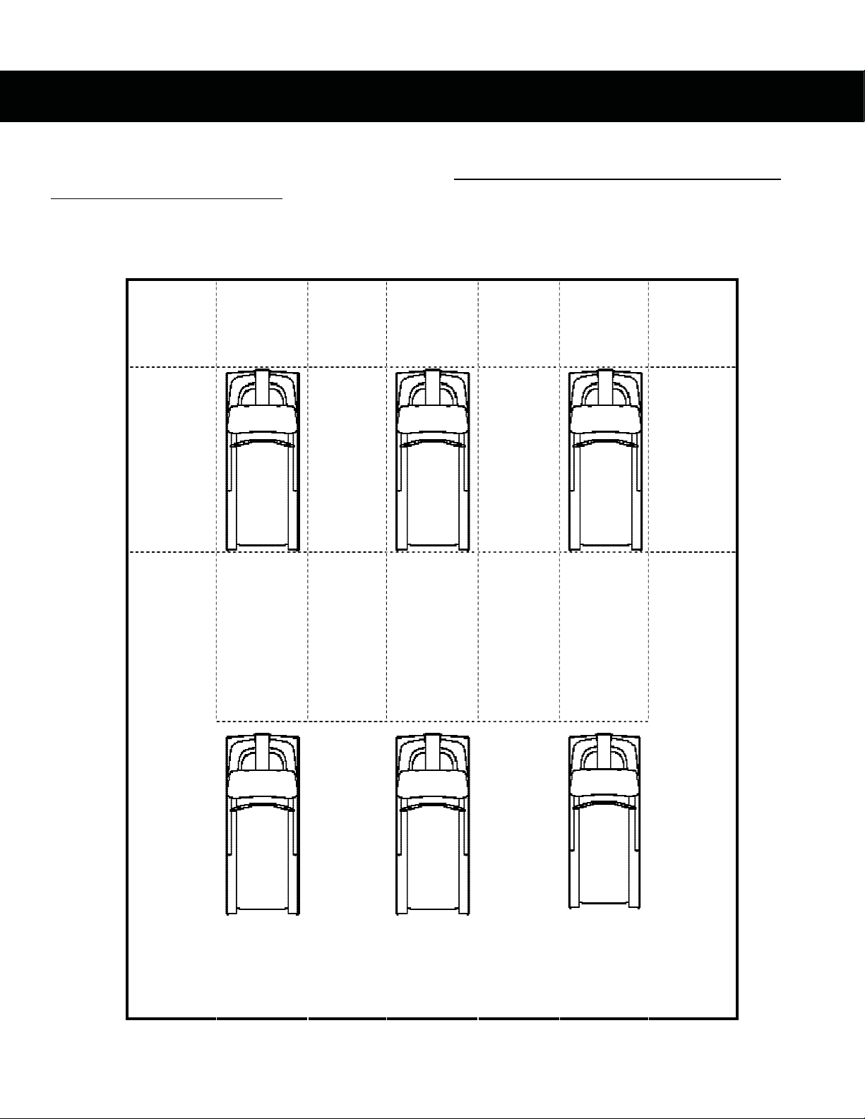
EQUIPMENT PLACING
Star Trac recommends that treadmills be spaced a minimum of 20.0 inches (0.5 m) apart to allow
safe and easy ingress and egress. More importantly, there must be at least 48 inches (1.25 m) of
free space behind the treadmill.
The Pro Series treadmill measures: 85.5” l by 34.0” w (217 x 86.5cm). See the following graph for
proper equipment spacing requirements:
inches
(0.5 m)
m 20.0 o
m 20.0 o
inches
(0.5 m)
inches
(1.25 m)
m 48.0 o
m 20.0 o
inches
(0.5 m)
m 20.0 o
m 48.0 o
inches
(0.5 m)
inches
(1.25 m)
m 20.0 o
inches
(0.5 m)
m 20.0 o
m 48.0 o
inches
(0.5 m)
inches
(1.25 m)
m 20.0 o
inches
(0.5 m)
5
Service Manual: E-TR and E-TRi
Page 8
POWER (ELECTRICITY)
Objectives
If you are not qualified/comfortable working with electricity you should consult a certified electrician.
This section should provide you with the information necessary to properly service your Star Trac unit
by giving you:
x A basic understanding of electrical safety
x A basic understanding of electrical terminology
x A basic understanding of electricity in general
x A basic understanding of electrical tools
x An overview of your Star Trac unit
Safety
See the “PRECAUTIONS – SAFETY” section of this manual.
Terminology
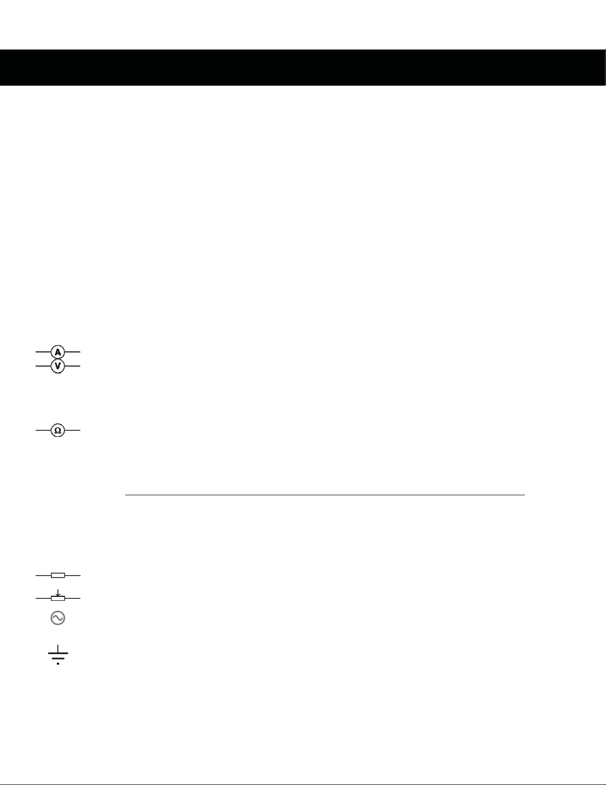
CURRENT – The number of electrically charged particles that flow past a given point on a
circuit in a given time
AMPERE (AMP) – A measure of current
VOLT – Measures the current pressure of a circuit
x Star Trac refers to the 2 most common global voltages as:
o 110V (or 110VAC)
o 220V (or 220VAC)
WATT – The rate at which an electrical device consumes energy
OHM – A measurement of resistance
o Ohm’s Law:
Current:
I = current, V = voltage, R = resistance
I = V / R
V
I =
R
Depending on what you are trying to solve, other variations can be made:
Voltage:
Resistance:
V = I x R
R = V / I
All variations of Ohm’s Law are mathematically equal to one another.
RESISTANCE – Used to dissipate passing current into heat to lower a voltage. Resistance
is measured in Ohm’s.
POTENTIOMETER (POT) – An electronic component which has an adjustable resistance
HOT wire – Delivers power to the unit. Typically has black, brown, or red insulation
NEUTRAL wire – Once electricity has done its work, it goes back through the neutral wire
to complete the circuit. Typically has white or blue insulation
GROUND wire – In addition to the neutral wire, the ground wire offers current another path
should an electrical short happen. Also help to dissipate static build-up from the running
belt and other components. Typically has green insulation (may be bare copper in some
cases)
6
Service Manual: E-TR and E-TRi
Page 9
General Electricity
Star Trac refers to the two most common global voltages as:
x 110V (or 110VAC)
x 220V (or 220VAC)
Voltages worldwide can vary. Star Trac products are designed to be stable within most voltages:
x For 110V systems the voltage range is: 110 VAC – 125 VAC 50/60hz
x For 220V systems the voltage range is: 190 VAC – 250 VAC 50/60hz
Electrical Tools
MULTIMETER – Used to test voltages, amperages and ohm readings. They
can vary on type from digital (as shown to the right) or analog. For this service
manual we will refer to the digital style for diagnostics.
Wiring
The 7600 or 7700 series treadmill is intended for commercial usage. Depending on the location type
and country a unit is manufactured for, it will come equipped with a special power cord and plug.
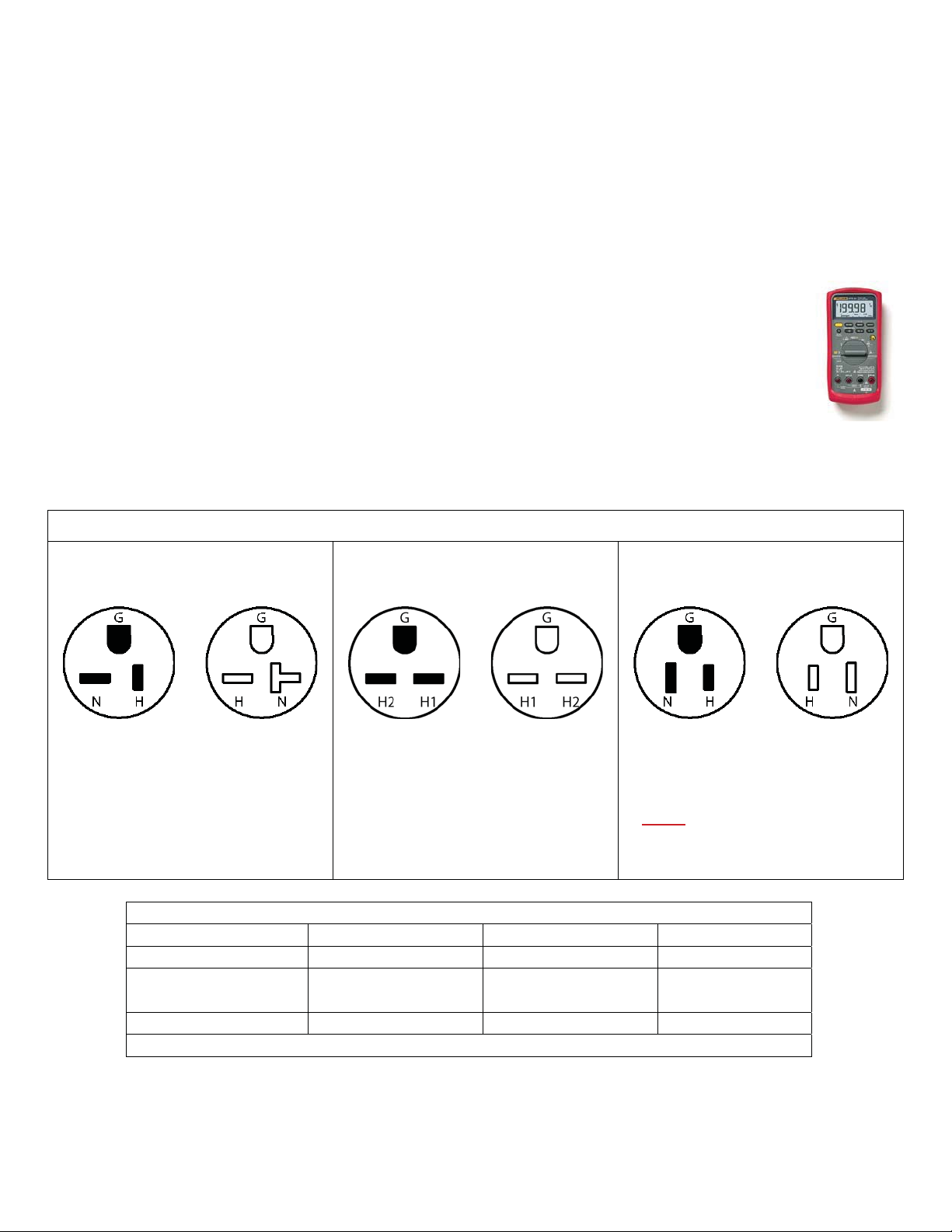
NEMA Configurations (U.S.A.)
110V Commercial 220V Commercial 110V Home
NEMA 5-20 NEMA 6-15 NEMA 5-15
Plug Receptacle Plug Receptacle Plug Receptacle
In this configuration, the HOT line is in
the normal 110V position, while the
NEUTRAL line has been turned 90q.
In this configuration, both the HOT and
NEUTRAL 220V lines are horizontal
(both opposite from the 110V config.)
This is the US standard 15 amp
configuration. Both HOT and
NEUTRAL lines are vertical.
THIS CONFIGURATION SHOULD
ONLY
BE USED ON TREADMILL
MODELS INTENDED FOR HOME
USE WITH A 15 AMP CIRCUIT
BREAKER!
Wire Configurations
HOT NEUTRAL GROUND
USA Wire
European Wire
Black White Green
Brown Blue Green/White
Green/Yellow
US Plugs
Small Flat prong Large Flat prong Round prong
Note: Some US units may have European wiring colors.
Star Trac treadmills require a “Dedicated” power line for proper operation and safety. Units should
never share a neutral or ground line. One 20 amp (or 15 amp) breaker per panel per treadmill only.
7
Service Manual: E-TR and E-TRi
Page 10
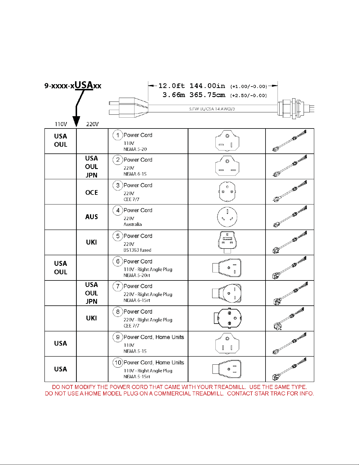
Power Cords
Below are the power cords you will find installed onto a Star Trac treadmill. Note the configuration of
the prongs for power and polarization:
8
Service Manual: E-TR and E-TRi
Page 11
PREVENTIVE MAINTENANCE
Overview
Preventive maintenance (PM) is a schedule of planned maintenance actions
aimed at the prevention of failures. PM is the best way to preserve and enhance
equipment reliability by keeping key components clean and free of debris. PM
activities may include cleaning, vacuuming, visual inspections of key
components, lubrication, etc. The better your PM program is, the more
dramatically you can increase the life of your product and significantly reduce
equipment failures.
Value of Preventive Maintenance
Long-term benefits of proper regular preventive maintenance include:
x Decreased product downtime
x Decreased cost of repair
x Improved product reliability
x Continuous user satisfaction
Long-term effects and cost comparisons usually favor preventive maintenance
over performing maintenance actions only when the system fails.
Determining When to Perform Maintenance
Some types of PM need to be performed more often than others. The frequency of PM depends a
great deal on the use and environment of the unit.
Star Trac has a baseline of procedures that should be performed at pre-determined intervals (as
outlined in the “Preventive Maintenance Schedule” section). It is imperative to understand that this is
a baseline and PM schedules should be adapted to the environment and usage that the unit receives.
Preventive Maintenance Cautions
x While maintaining equipment you will want to avoid spraying any liquids directly onto any
surface of the unit. Always spray cleaning solutions onto a clean towel first then wipe the unit.
x While vacuuming the floor area using an upright vacuum, avoid getting the power cord caught
in the beater-brush of the vacuum.
x Disconnect the power cord from the wall before vacuuming under the shroud.
x Use extreme caution while vacuuming around wires and/or electrical components under the
shroud.
x Do not attempt to clean the running belt with a mop
x Do not apply any cleaners, protectants or solutions onto the running belt (i.e. Armor All,
SlickStuff, belt dressing, etc.)
9
Service Manual: E-TR and E-TRi
Page 12
9
9
9
9
9
9
9
9
9
9
9
9
9
Preventive Maintenance Schedule
This section provides a comprehensive list of factory recommended PM requirements, along with
detailed procedures for performing each task.
DAI LY
WEEKLY
MONTHLY
AS NEEDED
Wipe down all surfaces including:
Display, handrails shroud and heart rate grips.
Clean under the running belt (soft cloth only)
Visually inspect running belt for alignment and tension
Ensure the power cord is not under the treadmill
Vacuum floor under and around treadmill
Inspect inside surface of running belt and top of deck
Correct any display or handrail squeaks and rattles
Visually inspect display panel (keypad) for wear
Vacuum inside shroud
Visually inspect the drive belt
Visually inspect the power cord for pinches or breaks
Wipe clean and lubricate elevation screws
Change belt and flip/new deck
Running belt & deck rewaxing*
* *
*Running Belt & Deck Rewaxing
The Pro Tread models 7600 and 7700 are equipped from the factory with a “Waxless” running belt
and deck system. It is not necessary to regularly wax, rewax or lubricate the running belt and deck.
Wax may be applied to alleviate running belt noise (see waxing instructions).
10
Service Manual: E-TR and E-TRi
Page 13
DAILY
Clean
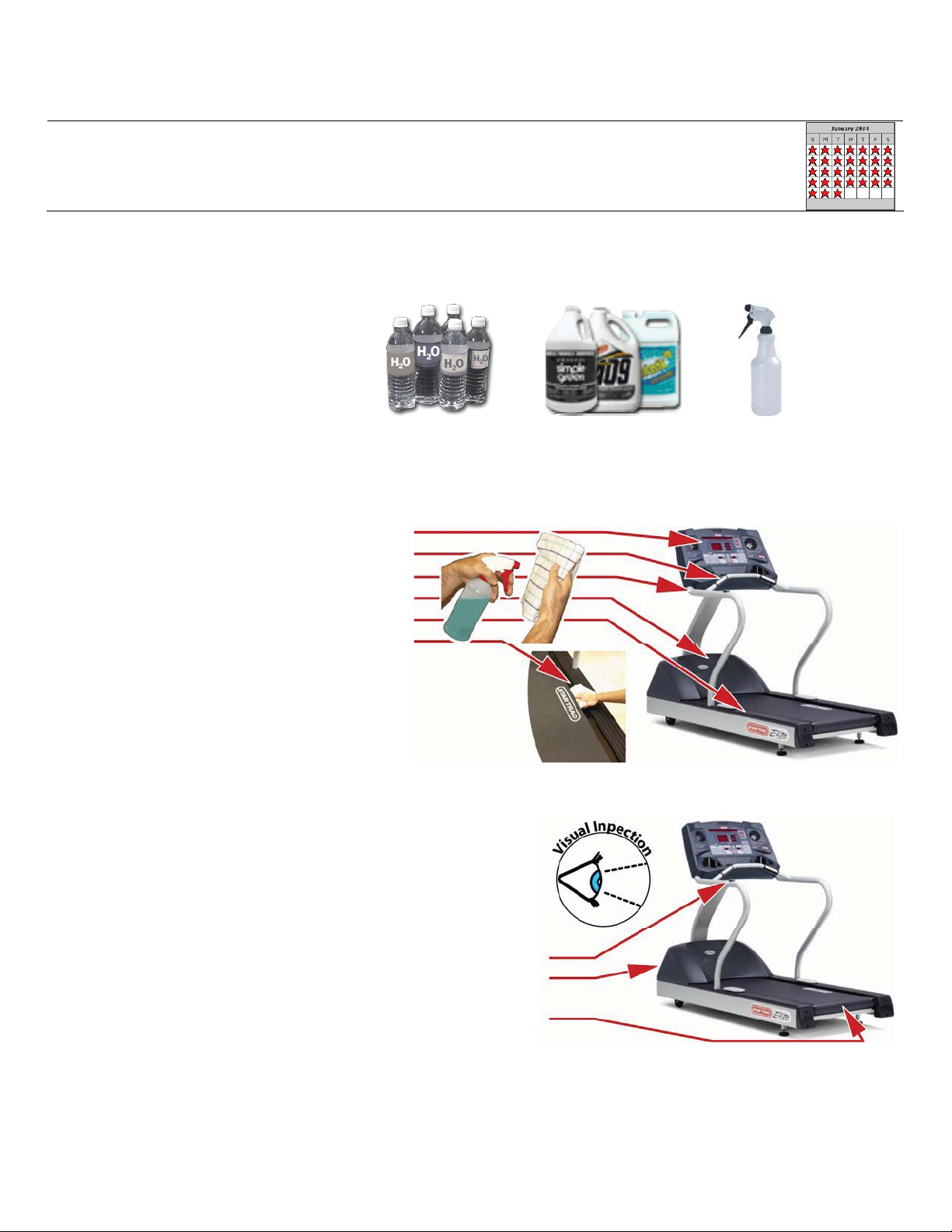
x Use a 5:1 dilution ratio (5 parts water to1 part Simple Green, Formula 409,
Fantastic,or the like).
+ =
(5 parts water) (1 part cleaner)
Apply cleaning solution to a clean cloth then wipe the following areas (Do not spray
directly onto surfaces):
o Display (Keypad)
o Heart Rate Grips
o Handrails
o Shroud
o Side Bed Covers
o Under Belt Edge
Inspect
x Inspect running belt for proper alignment
(see Running Belt section for adjustment)
x Inspect for wear and tear on exterior parts
to include:
o Side stop switch for function
o Shroud, housing and other
plastics for damage
o Running belt seam for tears or
splits
11
Service Manual: E-TR and E-TRi
Page 14
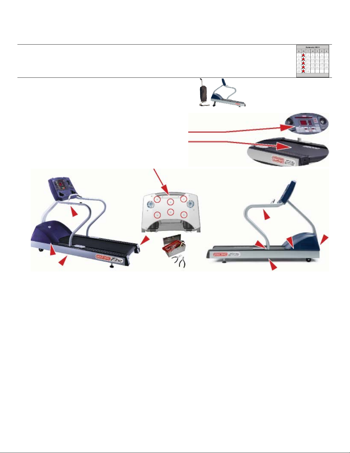
WEEKLY
Clean
Inspect
x Inspect display panel (keypad) for wear
x Inspect inside of running belt and top of
x Inspect all mounting hardware and
Elevate the treadmill and vacuum the floor
around and underneath.
deck
correct any squeaks or rattles
12
Service Manual: E-TR and E-TRi
Page 15
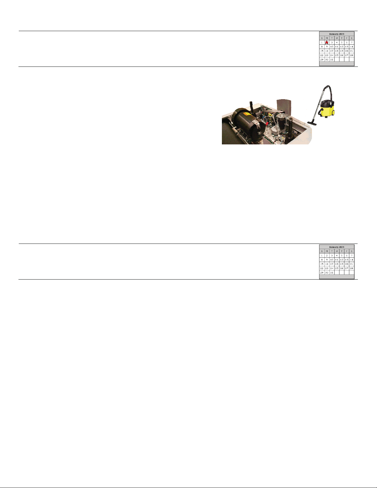
MONTHLY
Clean
x Unplug the treadmill and remove the
Inspect
x Inspect the drive belt for tension and wear.
x Inspect the power cord for pinches and/or
broken prongs
Lubricate
shroud. Use a portable vacuum with
dust attachment to clean any dust, dirt
or debris from inside the shroud area.
Use extreme caution to not damage
any components or knock and
connections loose
x Wipe and debris from the elevation screws then lubricate. Use a spray lithium grease or a
thin coating of grease. Avoid thin lubricants (i.e. TriFlow, WD-40, or the like).
AS NEEDED
Belt Service
x In high use locations, it may be advisable to replace the running belt with a new one to
prevent undetected wear. It is advisable to replace a running belt in a high use location in a
preventive manner, to prevent potential wear related issues. A worn or wearing belt can
cause undetectable issues.
13
Service Manual: E-TR and E-TRi
Page 16

RUNNING BELT
Once a deck surface has been used, it should not be used again.
You must install a new belt and new deck surface together. Most Star Trac decks are double-sided
so they can be flipped to utilize both sides. Failure to install a new belt over a fresh deck surface will
cause the belt to burn along the center walking area, the edges will curl, electrical components will
create so much heat as to begin to fail, and will not be covered under warranty.
The Pro Tread models 7600 and 7700 are equipped from the factory with a “Waxless” running belt
and deck system. It is not necessary to regularly wax, rewax or lubricate the running belt and deck
on these models. Wax may be applied to alleviate running belt noise (see waxing instructions).
During a non-belt and/or deck related service, if a running belt and/or deck are removed, it may be
acceptable to re-install the belt and deck as long as no visible signs of wear are present or the
situation does not require replacement.
If replacing a deck due to wear, it is advisable to replace the running belt as well, because wear is
commonly caused in conjunction with the running belt.
If you have questions on whether or not to replace a running belt and/or deck, contact Star Trac
Customer Support.
14
Service Manual: E-TR and E-TRi
Page 17

Importance of Running Belt Maintenance
The running belt is the most important part of a treadmill. It is what a treadmill is all about. It is the
core component that must be maintained to insure many years of continued function.
By performing a few maintenance steps at regular intervals, you can help to:
x Increase the life of a running belt
x Reduce unnecessary down-time
x Prevent electrical component failures
Dirt is an abrasive. When it builds up under a running belt, it can act like sandpaper, wearing off the
slick coating of the deck and reducing the life of both the running belt and deck surface.
Additionally, lack of proper PM can cause a running belt to over heat and can delaminate (separate
the layers of the belt) resulting in curled edges, folded edges and ripples in the center of the walking
area.
Checking for proper running belt tension can help ensure that the running belt is not too loose. If a
running belt is too loose, it has the potential of tracking to the side and becoming damaged.
A worn running belt will cause other components (i.e. MCB, Drive Motor, etc.) to develop enough heat
that over time will cause failure to those components.
Taking care of a running belt at regular intervals can greatly reduce maintenance costs and
unnecessary downtime.
Running Belt “Do Not’s”
x Do not use Armor All, Slick Stuff, WD-40 or the like, on the running surface of a belt
x Do not use cleaners with ammonia or alcohol on the belt
x Do not use any lubricants under the running belt
x Do not over-tension a running belt
x Do not wash a running belt then reinstall it
x Do not reuse a deck surface when installing a new running belt
15
Service Manual: E-TR and E-TRi
Page 18

Cleaning a Running Belt
The running belt should be cleaned to help prevent dirt build up and maintain a nice appearance for
users.
To properly clean a running belt you will need:
TOOLS & MATERIALS
x Clean towel (1)
x Paint stick or ruler (1)
x Diluted all-purpose cleaner (409, Simple Green, etc.)
x Bristle brush
CLEANING PROCEDURE:
1. CLEAN BETWEEN DECK & BELT:
A. Using the paint stick or ruler, slide a dry towel under the middle of the belt from one side of the
frame to the other.
B. Hold the edges of the towel and pull towards the tail roller then pull back towards the head
roller.
C. Rotate the running belt around and repeat to completely wipe the entire underside of the belt.
TIP: Fold the dirty towel and shake into trash.
2. CLEAN BELT SURFACE
Spray the diluted cleaning solution onto a towel then wipe the running belt surface. For
heavier soiled areas, spray a tiny bit of solution onto the spot and use the bristle brush to
gently agitate the spot then wipe with the towel.
3. CLEAN SIDEBED COVERS
Spray the towel with cleaning solution to give a final wipe of the sidebed covers to help ensure
cleanliness.
16
Service Manual: E-TR and E-TRi
Page 19

Running Belt Tension
Proper running belt tension and tracking are important to maintain the performance and life of the
belt. It is recommended to follow this tensioning and tracking procedure whenever the running belt or
deck is replaced or as needed.
PARTS REQUIRED
x Masking tape and pen or pencil
x Ruler or tape measurer
TOOLS REQUIRED
x 1/4” Allen wrench
FREQUENCY
After: 1,000 Miles (1,600 Km) OR 1 Month. Whichever comes first.
x Clean deck with dry cloth and retighten belt using procedure below.
After: 6,000 Miles (10,000 Km) OR 6 Months
12,000 Miles (20,000 Km) OR 12 Months
18,000 Miles (30,000 Km) OR 18 Months
24,000 Miles (40,000 Km) OR 24 Months
30,000 Miles (50,000 Km) OR 30 Months
OR whichever comes first.
x Clean deck with dry cloth. Clean between the belt and deck using the “Cleaning A
Running Belt” section. Clean the head and tail rollers using the “Roller Care &
Maintenance” section. Retighten belt using the following procedure “Running Belt
Retensioning Procedure”.
17
Service Manual: E-TR and E-TRi
Page 20
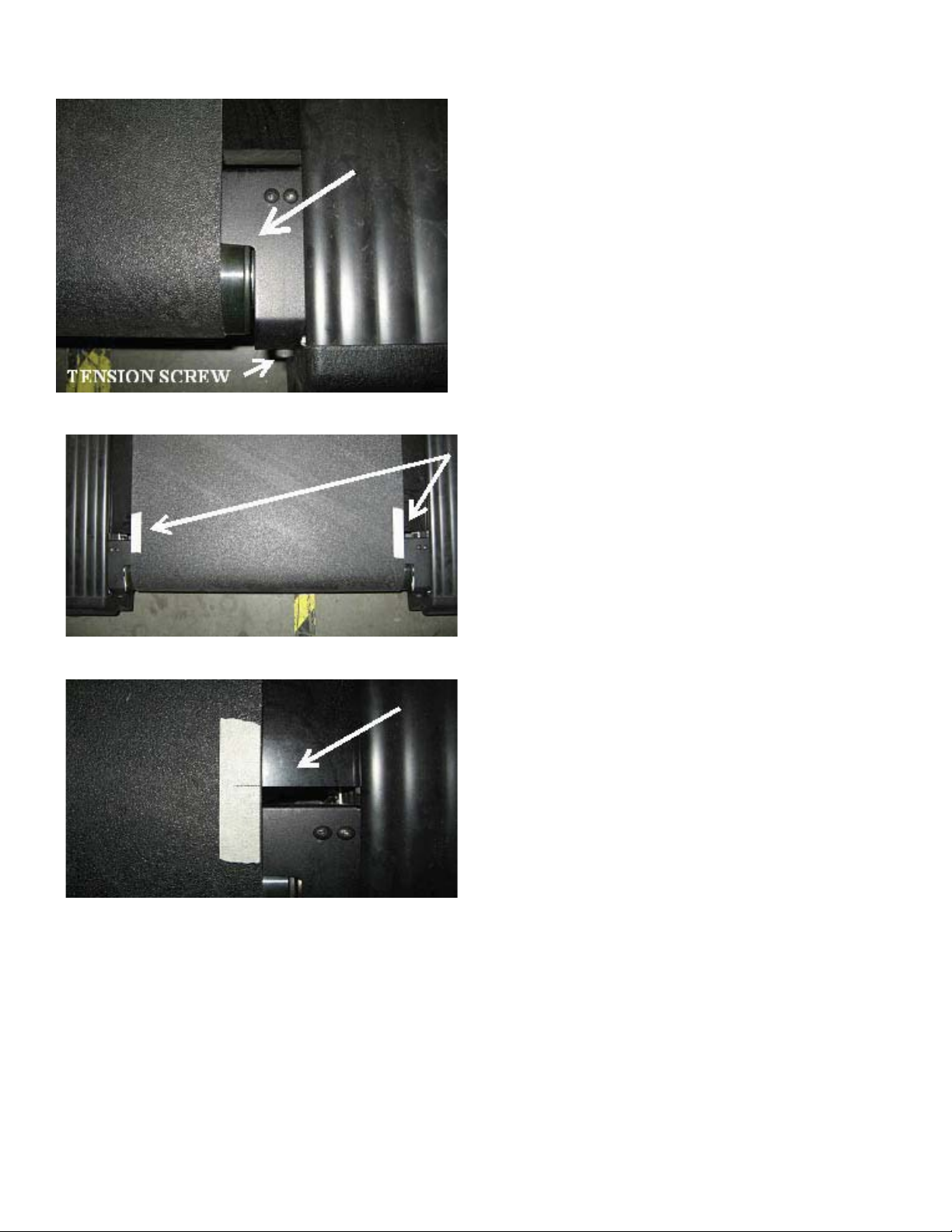
RUNNING BELT RETENSION PROCEDURE
Fig 1
Step 1: Release tension of running belt by
unscrewing the tension screws until the roller
touches the finger-guard. The belt should be
completely relaxed.
(Note: This applies to both left & right fingerguards.)
Step 2: Apply a piece of masking tape on the
edge of the running belt on both sides.
Fig 2
Fig 3
Step 3: Draw a line on each piece of masking
tape aligned with the edge of the deck.
(Note: Be careful not to move the belt or roller
while drawing the lines.)
18
Service Manual: E-TR and E-TRi
Page 21
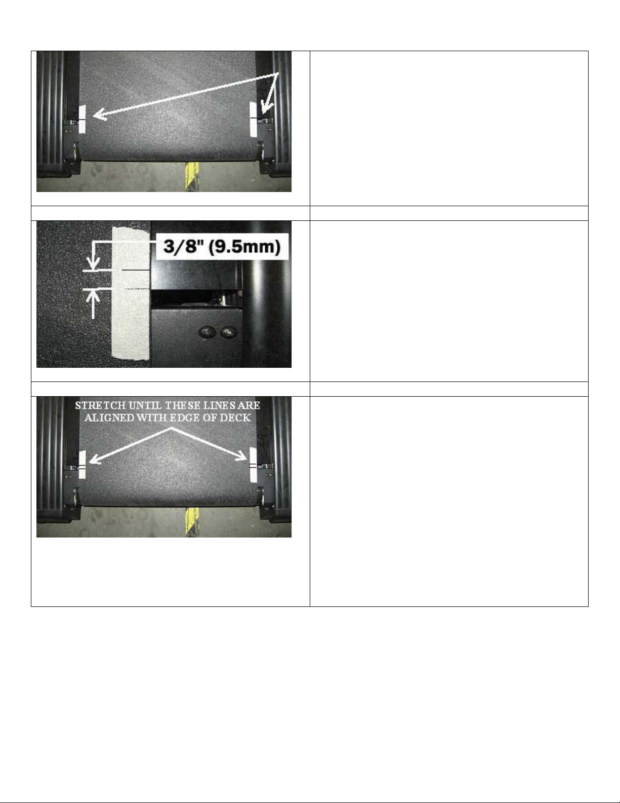
Step 4: Check to make sure that both lines are
aligned with the edge of the deck at the same
point. (See Fig 4)
Fig 4
Step 5: Using a ruler or tape measure, draw a
line on each piece of tape parallel to each first
line at a distance of 3/8” (9.5mm) from each first
line. (See Fig 5)
Step 6: You are now ready to begin tensioning
the belt. Before beginning, make sure the line on
each piece of tape closest to the tail roller is
aligned with the edge of the deck on each side.
(See Fig 5)
Fig 5
Step 6: Using the 1/4" Allen wrench begin
tightening the tensioning screws (see Fig 1). You
will tighten (or stretch) the run belt until the
forward lines on the tape are aligned with the
edge of the deck.
Be careful to ensure the Tail Roller does not
turn while you are stretching the belt. If the
Tail Roller turns while you are stretching the
belt, start the procedure over. If the Tail
Fig 6
Roller turns while stretching the belt you will
not obtain proper tension.
When finished, remove the tape from the running
belt.
19
Service Manual: E-TR and E-TRi
Page 22

Running Belt Alignment
Step 1: Start the treadmill and set the speed to
3.0 mph (5.0 kmh). Make sure the running belt
tracks to the center (see Fig 7).
If the running belt shifts or tracks to either side
(left or right), follow the appropriate procedure
below.
Fig 7
To move belt back towards the center
if it has tracked to the LEFT side:
Turn the LEFT
bolt ¼ turn
clockwise
To move belt back towards the center
if it has tracked to the RIGHT side:
Turn the RIGHT
bolt ¼ turn
counter-clockwise
Repeat above steps until the running belt tracks in the center.
Turn the LEFT
bolt ¼ turn
counter-clockwise
bolt ¼ turn
Turn the RIGHT
clockwise
20
Service Manual: E-TR and E-TRi
Page 23

Roller Care & Maintenance
The care and maintenance of the head and tail rollers are as important as the care and maintenance
of the running belt. Dirt buildup on the rollers can cause noise, rough feelings and unwanted belt
tracking.
CLEANING
Scrape any dirt and debris build up from the roller using a plastic scraper or an old credit card. Do
not use anything metal or sandpaper, as you will damage the coating on the roller. Vacuum up any
debris from the rollers.
ROLLER “DO NOT’s”
x
Do not lubricate the roller bearings. They are a sealed type bearing and any lubricant you
attempt to apply, will not penetrate the seal.
x Do not scrape a roller with metal. Use a plastic scraper or a credit card only.
x Do not use sandpaper to clean the rollers
21
Service Manual: E-TR and E-TRi
Page 24

S
S
A
AFFEETT
Y
Y FFII
R
R
S
STT!!
Applying Wax to a Waxless Running Belt
While it is generally not necessary to add wax to a waxless style running belt, if the running belt is
making unacceptable noises or is experiencing tracking difficulties, adding wax the underside of the
belt will improve the grip between the belt and the rollers which will reduce the noise and improve the
tracking response. This procedure should ONLY be performed by a person that is familiar with
waxing of running belts and is physically able to do so.
Parts Required
x Bottle of Micronized Powdered Paraffin Wax (Part No. 140-3180)
x #2 Phillips screwdriver
x Towel - 36” x 12” (90cm x 30cm) is suggested
x Plastic drinking straw – large diameter
Caution should be exercised at all times when performing the following procedure. If
you do not feel comfortable with this, stop immediately and obtain the services of a
qualified Service Provider.
Step 1:
x Place the towel between the deck and the running belt (Fig 1).
x Step on the sides of the towel and run the treadmill at 2 mph (3 kmh) (Fig 2).
¾ Make sure the towel does not come loose while the running belt is moving.
x Run the treadmill for about 1 minute then stop the treadmill.
x When the treadmill stops, remove the towel (Fig 3).
x Wipe around the deck edges with the clean part of the towel.
Fig 1
Fig 2
Fig 3
22
Service Manual: E-TR and E-TRi
Page 25

Step 2:
x Using the screwdriver, remove the three screws from the left and the three screws from
the right finger guards (Fig 4).
x Remove both finger guards (Fig 5).
Fig 4
Fig 5
CAUTION
Be mindful of loose clothing, long hair, loose and/or hanging jewelry, etc.
Step 3:
: The next step involves working near moving parts. BE CAREFUL!
x Insert the straw onto the bottle of wax (Fig 6).
x Start the treadmill at 3.0 mph (5.0 kmh).
x While the treadmill is running, squirt about 5-8 times on the left
side onto the underside of the running belt (Fig 7) and 5-8 times
on the right side onto the underside of the running belt (Fig 8).
x Check the bottle and make sure you have used at least half
bottle of wax (Fig 9). It may be necessary to use a full bottle
x Run on the treadmill for about 2 minutes.
the
Fig 6
Fig 7
Step 4:
x Stop the treadmill and reinstall both finger guards with screws (Fig 11).
x Wipe off any excess wax (Fig 12).
Fig 11
Fig 8
Fig 12
Fig 9
23
Fig 10
Service Manual: E-TR and E-TRi
Page 26

MAINTENANCE MODE
The Maintenance Mode allows you to query and modify the settings of the Star Trac product.
Engaging Maintenance Mode
Press and hold the
While holding all three keys release the
+ + keys.
key only.
A beep will sound and the display will
read “MAINTENANCE MODE”
momentarily in the information window.
Once in the Maintenance Mode release all of the keys.
The display will read “UNITS:
ENGLISH” (or “UNITS: METRIC”)
depending on your settings.
You will now be in the Maintenance Settings mode for you unit. As a safety precaution, the unit will
only stay in the Maintenance Mode for approximately 45 seconds after the last key stroke entry. As
long as you are adjusting settings or scrolling through parameters, the unit will stay in mode.
24
Service Manual: E-TR and E-TRi
Page 27

WARNING
Maintenance Mode Keys
The following keys are used to search through and modify the Maintenance Settings:
INCLINE keys: Display the next and previous parameters.
SPEED keys: Adjust the value of the displayed parameter up and down
respectively. Some parameters can utilize the number pad.
ALPINE PASS: Sets parameter back to its default factory setting. Note:
For parameter “LAST DECK” this key will set the parameter to the current
“MILEAGE” value to clear the “REWAX BELT” message.
OK key: Updates (saves) the value of the display setting in the memory.
START key: Used to initially enter the Maintenance Mode and updates
changed parameter values.
NUMBER PAD: Used to directly enter numeric values.
STOP key: Used to exit the Maintenance Mode.
Do not operate the unit for a workout while in the Maintenance Mode or Motor Test Modes.
25
Service Manual: E-TR and E-TRi
Page 28

DISPLAY PARAMETERS
Parameter Defaults
The following parameters can be accessed by entering the Maintenance Mode. When installing a
new display electronic board, it will come with factory default settings. Depending on the model and
voltage of unit you are installing the board into, you may need to adjust your settings by referencing
the following chart.
Parameter 110V Setting 220V Setting Default Parameter Ranges
UNITS
MINIMUM SPEED
MAXIMUM SPEED
ELEVATION
TIME
OPER HOURS
DISTANCE
WEIGHT
SERIAL NO
LANGUAGE
ENTRY
HEART RATE
METS
WATTS
PAUSE
SCALE
INFRARED COM
CSAFE
FAN
AUTO STOP
ENTERTAINMENT
ACCELERATION TIME
DECELERATION TIME
LOCK OUT
LOCK OUT ID
RAIL STOP
STOP SWITCH
10_REV
CNT/REV
MINUMUM PWM
1/2 MAXIMUM
MAXIMUM PWM
PERSON DETECT 1
PERSON DETECT 2
PERSON DETECT 3
DATE
ENGLISH ENGLISH, METRIC
0.5
(0.8kph)
10.0
(16.0kph)
ON OFF, ON
99 20 - 99
0 0 – 65535
155 0 – 350
0 0 – 65535
ENGLISH ENGLISH, DUTCH, FRENCH,
UNITS UNITS, TENTHS
BOTH CONTACT, POLAR, BOTH
OFF OFF, ON
OFF OFF, ON
45 20 – 120
ON OFF, ON
ON OFF, ON
ON OFF, ON
ON OFF, ON
OFF OFF, ON
OFF OFF, ON
35 25 – 60
30 20 - 60
OFF OFF, ON
12345 0 - 65535
ON OFF, ON
E-STOP E-STOP, LANYARD
376 376 376 0 – 740
31 31 31 0 – 125
(VARIES) (VARIES) 34 0 – 110
(VARIES) (VARIES) 200 0 – 340
(VARIES) (VARIES) 400 0 – 495
17 17 17 0 – 150
30 30 30 0 – 150
40 40 40 0 – 150
1.98 0.00 – 9.99
0.5
(0.8kph)
12.0
(20.0kph)
0.5
(0.8kph)
12.5
(kph)
0 0 – 65535
0.5 – 5.0
(0.8 – 8.0kph)
5.0 – 12.5
(8.0 – 20.0kph)
GERMAN, PORTUGUESE,
SPANISH, SWEDISH, ITALIAN,
KATAKANA
26
Service Manual: E-TR and E-TRi
Page 29

Parameter 110V Setting 220V Setting Default Parameter Ranges
NO RAIL STOP
KEY DOWN
SPEED CHG
ELEV STALL
ELEV RANGE
ELEV LOST
CHECK MOTOR SYS
ERROR CAPTURES
PROGRAM CAPTURES
CHECK SPEED SYS
FUSE BITS ERROR
ELEVATION ZERO
ELEVATION MAX
LAST DECK
LAST BELT
LAST MOTOR
CS AUTO STATUS
MODEL
HR CALC. TIME
MANUAL
FOREST WALK
TRAIL
ALPINE PASS
RANDOM
5K LOOP
10K LOOP
CUSTOM PALM
DYNAMIC HR
CONSTANT HR
QUICKSTART
FITNESS TEST
FIRE FIGHTER
US ARMY TEST
USMC TEST
USAF TEST
NAVY TEST
0 0 – 65535
0 0 – 65535
0 0 – 65535
0 0 – 65535
0 0 – 65535
0 0 – 65535
0 0 – 65535
0 0 – 65535
0 0 – 65535
240 240 240 0 – 242
70 70 70 0 – 170
0 0 – 65535
0 0 – 65535
0 0 – 65535
ON OFF, ON
PRO AC PRO S, PRO, PRO ELITE,
PRO AC, PRO ELITE AC
30 0 – 99
0 0 – 65535
0 0 – 65535
0 0 – 65535
0 0 – 65535
0 0 – 65535
0 0 – 65535
0 0 – 65535
0 0 – 65535
0 0 – 65535
0 0 – 65535
0 0 – 65535
0 0 – 65535
0 0 – 65535
0 0 – 65535
0 0 – 65535
0 0 – 65535
0 0 – 65535
Note: Some parameters shown above may or may not display in your unit.
27
Service Manual: E-TR and E-TRi
Page 30

Parameter Setting Definitions
The following are the definitions of each parameter from the Maintenance Mode.
UNITS:
MINIMUM SPEED:
MAXIMUM SPEED:
ELEVATION:
TIME:
OPER HOURS:
DISTANCE:
WEIGHT:
SERIAL NO:
LANGUAGE:
ENTRY:
HEART RATE:
METS:
WATTS:
PAUSE:
SCALE:
INFRARED COM:
CSAFE:
FAN:
AUTO STOP:
ENTERTAINMENT:
ACCELERATION
TIME:
DECELERATION
TIME:
LOCK OUT:
LOCK OUT ID:
Footnotes:
1 When replacing a display electronic board, it is a good idea to write down this number and set it into the
new electronic board to help keep accurate records of parameters with the unit.
2 When resetting the Rewax Belt message (LAST DECK parameter), this is the number that will automatically
be copied into the LAST DECK parameter to set the current mileage.
Sets the conversion for speed, distance and weight between US and Metric
measurements. (Conversions: Km = Miles x 1.6 x Lb = Kg x 2.2)
Sets the minimum start up speed for the unit.
Sets the maximum speed available for the unit.
Turns the elevation (incline) system on or off.
Sets the maximum workout time for the unit. Can be used in a high-use facility
or location that wishes to limit usage times of a unit.
The accumulation of hours the unit has been used
The accumulation of miles the unit has been used
1
1,2
Sets the default weight, usually 155 lbs (70 kg) that the unit will use to
calculate calories to be used if a user does not enter their weight during
workout setups.
The last few numbers of the unit serial number. *May or may not be used
Sets the language that the display will show.
Sets how the numbers will be entered during key strokes:
(UNITS = 1.0 increments, TENTHS = 0.1 increments)
Sets the type of Heart Rate to use: (POLAR only, CONTACT only or BOTH).
Used for workout feedback. *Consult an Owners Manual or a certified trainer
for definition.
Used for workout feedback. *Consult an Owners Manual or a certified trainer
for definition.
Sets the amount of time in seconds that a unit will pause when the side stop
switch or the stop key is pressed during a workout.
Turns the scale feature on or off.
Turns the infrared communication system on or off.
Turns the CSafe power outlets on or off.
Turns the fan system on or off.
*Not used at this time. Be sure this parameter is set to OFF.
Turns the entertainment system on or off.
Sets the amount of time the unit will take (in seconds) to go from 0.0 mph to
achieve the maximum speed as set in the MAXIMUM SPEED parameter.
Sets the amount of time the unit will take (in seconds) to go from the maximum
speed as set in the MAXIMUM SPEED parameter down to 0.0 mph.
Used to disable use of the unit unless the LOCK OUT ID has been entered.
A number combination used to lock out the display from use.
1
28
Service Manual: E-TR and E-TRi
Page 31

RAIL STOP:
Used to turn the side stop switch port on or off on International units.
*Note: This parameter should always be ON unless the mechanical stop
switch is installed.
STOP SWITCH:
10_REV:
Sets the type of International stop switch is in use: U.S.A. or International
Sets the speed and distance calculation value. This is the distance (in
inches) that the running belt travels for every 10 revolutions of the drive
1
CNT/REV:
motor
Sets the number of timing notches (or target ticks) that the RPM sensor
passes in each revolution of the RPM target1
MINIMUM PWM:
1/2 MAXIMUM:
MAXIMUM PWM:
PERSON DETECT 1:
PERSON DETECT 2:
PERSON DETECT 3:
DATE:
Sets the PWM value the unit needs to calculate the MINIMUM SPEED3
Sets the PWM value the unit needs to calculate half of the MAXIMUM
SPEED
3
Sets the PWM value the unit needs to calculate the MAXIMUM SPEED3
An internal calculation setting. Leave at default setting.
An internal calculation setting. Leave at default setting.
An internal calculation setting. Leave at default setting.
The date of manufacture of the unit. *May or may not be used
1
The following parameters are used to keep track of Error Codes that may have been displayed during
use. These should be reset (defaulted) back to 0 (zero) during each maintenance session.
To Reset: While on the parameter, press the “ALPINE PASS” key to reset value to 0, then press the “OK”
key or the “START” key to save the change.
NO RAIL STOP:
Side stop switch (in left handrail) disconnected or broken. Rare occasions
may be caused by faulty display electronic board.
KEY DOWN:
One or more keys on the display panel may be sticky or stuck. Rare
occasions may be caused by faulty display electronic board.
SPEED CHG:
Defined as a change in the speed feedback of 2.0 mph or more in more than
2 seconds.
ELEV STALL:
The elevation system did not detect any elevation movement, or the system
moved too slow.
ELEV RANGE:
The elevation system detected it went too high or too low than what the
parameters are set to.
ELEV LOST:
The elevation system has lost communication with the elevation sensor
inside the elevation motor.
CHECK MOTOR
SYS:
CHECK SPEED SYS:
See the TROUBLESHOOTING - CHECK MOTOR SYSTEM section of this
manual.
See the TROUBLESHOOTING - CHECK SPEED SYSTEM section of this
manual.
FUSE BITS ERROR:
Footnotes:
1 When replacing a display electronic board, it is a good idea to write down this number and set it into the
new electronic board to help keep accurate records of parameters with the unit.
3 When replacing a display electronic board, it is not necessary to change this value. It will automatically
Change during the Auto-Calibration procedure.
Fault during software upload.
29
Service Manual: E-TR and E-TRi
Page 32

ELEVATION ZERO:
ELEVATION MAX:
LAST DECK:
Sets the value for 0% (zero percent) for the elevation motor sensor.
Sets the value for 15% (maximum incline) for the elevation motor sensor.
This parameter is used for models with a waxable
have a waxless
style treadmill and REWAX BELT appears on your display,
style running belt. If you
go to the MODEL parameter and make sure your unit is set for the correct
model.
LAST BELT:
A parameter available for you to enter the mileage (DISTANCE) at which the
running belt was replaced. This aids in your record keeping.
LAST MOTOR:
A parameter available for you to enter the mileage (DISTANCE) at which the
drive motor was replaced. This aids in your record keeping.
CS AUTO STATUS:
MODEL:
An internal calculation setting. Leave at default setting.
Sets the model that the display electronic board will be used on. Note that
some features may not work (fans, scales, entertainment, etc.) if this setting
is incorrect.
HR CALC. TIME:
Sets the amount of time the Heart Rate system will seek to acquire a heart
rate reading before it resets and begins seeking again if not detected.
The following parameters are used to keep track of which programs users are selecting. These
parameters do not affect the functionality of the unit, but can be used to log the types of programs
users prefer to use.
MANUAL
FOREST WALK
TRAIL
ALPINE PASS
RANDOM
5K LOOP
10K LOOP
CUSTOM PALM
DYNAMIC HR
Check with a Star Trac sales representative for definitions
CONSTANT HR
QUICKSTART
FITNESS TEST
FIRE FIGHTER
US ARMY TEST
USMC TEST
USAF TEST
NAVY TEST
30
Service Manual: E-TR and E-TRi
Page 33

MAINTENANCE MODE – TEST MODES
Within the Maintenance Mode parameters are a few Test Modes that can be used to test various
functions of the unit. While in the Maintenance Mode, set the following parameter and use the
functions as listed to utilize each parameter.
DISPLAY TEST
The Display Test can be used to test each individual key for function and response, and can
also be used to verify led function and display.
Press ‘Start’ key
Press ‘Start’ key
Press ‘Start’ key
Press ‘Start’ key
Press ‘Stop’ key twice to return to the MAINTENANCE MODE
Press ‘1’ key
Press ‘Speed Plus’ key
Press ‘Speed Minus’ key
Press ‘Stop’ key twice to return to the MAINTENANCE MODE
Press ‘2’ key
Press ‘Stop’ key to verify function then press again to return to the MAINTENANCE MODE
Note: You can also access the Display Test right away when entering the Maintenance Mode:
When the display reads UNITS: ENGLISH (or UNITS: METRIC),
press the ‘5’ key then follow the procedures above.
Display will enter DISPLAY TEST and await your next command
Display will cycle thru a self test and display all led’s in a sequenced pattern
Display will enter DISPLAY TEST and await your next command
MC1 Vx.x CKSM xxxx will display
MC2 Vx.x CKSM xxxx will display
MC1 Vx.x CKSM xxxx will display
Display will enter DISPLAY TEST and await your next command
Display will read KEYBOARD TEST
Press any key except ‘Stop’ to verify function.
Loop
MOTOR TEST
This parameter is used by Star Trac at the factory.
*For MOTOR TEST MODE, see the MOTOR TEST MODE section of this manual.
BELT/DECK TEST
This parameter is used by Star Trac at the factory.
31
Service Manual: E-TR and E-TRi
Page 34

CALIBRATE SCALE
Press ‘Start’ key
Enter your exact weight *It is advisable to weigh yourself for accuracy just before performing this step.
After entering your weight press either the ‘Start’ or ‘OK’ keys.
Display will read :
If no weight entered, unit will read:
If no weight entered, unit will read:
If no load cells detected, unit will read:
Press ‘1’ key
Press ‘2’ key
Press ‘3’ key
Press ‘4’ key
Press ‘Stop’ key once to return to the CALIBRATE SCALE mode
Press ‘Stop’ key a second time to return to the MAINTENANCE MODE
Display will enter CALIBRATE SCALE mode and scroll the following:
1 = INPUT SPAN WEIGHT
2 = CAL SPAN WEIGHT
3 = CAL ZERO WEIGHT
Loop
4 = VERIFY WEIGHT
PRESS STOP TO EXIT
Pressing ‘Stop’ will return to MAINTENANCE MODE
Unit will read REF WEIGHT = 155
STEP ON WEIGHT PADS
PRESS OK TO BEGIN
Loop
Pressing ‘OK’ will read CALIBRATING X (X = your entered weight)
CAN NOT CALIBRATE
NO WEIGHT ACQUIRED
PRESS OK TO RETRY
PRESS STOP TO EXIT
Loop
Pressing ‘OK’ will return to previous step
Pressing ‘Stop’ will return to MAINTENANCE MODE
Display will read:
PLACE CAL WEIGHT
ON WEIGHT PADS
PRESS OK TO BEGIN
Loop
After pressing ‘OK’ unit will read CALIBRATING X (X = calibrated weight)
CAN NOT CALIBRATE
NO WEIGHT ACQUIRED
PRESS OK TO RETRY
PRESS STOP TO EXIT
Loop
Pressing ‘OK’ will return to previous step
Pressing ‘Stop’ will return to MAINTENANCE MODE
Display will read:
REMOVE WEIGHTS
PRESS OK TO BEGIN
After pressing ‘OK’ unit will read CALIBRATING X (X = weight zero)
CAN NOT CALIBRATE
NO WEIGHT ACQUIRED
PRESS OK TO RETRY
PRESS STOP TO EXIT
Loop
Pressing ‘OK’ will return to previous step
Pressing ‘Stop’ will return to MAINTENANCE MODE
Display will read: WEIGHT= 0 and display the weight as detected
32
Service Manual: E-TR and E-TRi
Page 35

º
¼
CSAFE TEST
This parameter is used by Star Trac at the factory.
HEART RATE TEST
The Heart Rate Test mode can be used to simultaneously test the function and response for
both the contact and Polar heart rate systems.
Press ‘Start’ key
, , Grab the HR grips
(If applicable) Polar strap *If you have a Polar transmitter or a polar signal simulator then signal will be detected
Press ‘Stop’ key twice to return to the MAINTENANCE MODE
INFRARED TEST
This parameter is used by Star Trac at the factory.
Display will read POLAR 0 CONTACT 0
CONTACT X should detect your heart rate then display the reading
and processed by the Polar system and display the value as POLAR X
LAST ERROR LIST
The Last Error List is a list bank of the last five issues the unit has captured into its memory for
diagnosis of an issue. To access the Last Error list banks, follow the procedure below. For
more information including DFR, see the DFR section in this manual.
Press ‘Start’ key
Press ‘Start’ key
Press ‘Start’ key
When opening the banks, #1 is the first code that was captured, #2 the second, #3 the third
and so on. If more than 5 codes have been captured, bank #5 will always be the latest code
captured and the previous number will be replaced accordingly.
For a list of definitions for the Last Error List, see the LAST ERROR LIST DEFINITIONS
section in this manual.
Press ‘Start’ key
Press ‘Stop’ key twice to return to the MAINTENANCE MODE
Press ‘1’ key
Press ‘Speed Plus’ key
Press ‘Speed Minus’ key
Press ‘Stop’ key twice to return to the MAINTENANCE MODE
Press ‘2’ key
Press ‘Stop’ key to verify function then press again to return to the MAINTENANCE MODE
Display will enter DISPLAY TEST and await your next command
Display will cycle thru a self test and display all led’s in a sequenced pattern
Display will enter DISPLAY TEST and await your next command
MC1 Vx.x CKSM xxxx will display
MC2 Vx.x CKSM xxxx will display
MC1 Vx.x CKSM xxxx will display
Display will enter DISPLAY TEST and await your next command
Display will read KEYBOARD TEST
Press any key except ‘Stop’ to verify function.
Loop
33
Service Manual: E-TR and E-TRi
Page 36

MAINTENANCE MODE – AUTO CALIBRATION
Electrical voltages vary between locations. The treadmill can run through an auto-calibration process
to allow the electronics to balance out with the speed control.
To run an auto-calibration procedure, do the following:
Auto-Calibration
DO NOT LEAVE THE TREADMILL UNATTENDED WHILE RUNNING
THE AUTO-CALIBRATION PROCEDURE AS IT WILL RUN THE
BELT TO THE MAXIMUM SPEED SETTING.
1. Enter the Maintenance Mode (see “Engaging Maintenance Mode”).
The display will read:
2. Enter the Motor test mode by pressing the ‘8’ key once. The display
will read:
3. Start the auto-calibration process by pressing the ‘Forest’ key once
and immediately stepping off of the treadmill.
The center number (3) as shown above, will begin to increase, running
belt will move and the center number will on the right hand side of the
display (0.0) will move .
The treadmill running belt will begin to move in the following manner:
x Running belt will move, center number will increase and the
numbers on the right hand side of the display ‘0.0’ will move
34
Service Manual: E-TR and E-TRi
Page 37

DEFINITIONS
LAST CODE
LST CHK
LAST MTR CURR
LAST STAT
LAST OPHR
LAST ODOM
LAST PRGM
LAST DFR
LAST TIME
LAST MSPD
LAST PWM
LAST SSPD
LAST EPOT
LAST ELEV
LAST ERROR LIST DEFINITIONS
The last code (Check Speed Sys, Key Down, Elev Stall, etc.)
Check Sum at time of incident. Check Sum is part of the software language.
Motor Current sensed at time of incident.
Total unit OPER HOURS (Operating Hours) at time of incident.
Total unit DISTANCE (mileage) at time of incident.
Program that was running at time of incident.
See DFR INFO below.
Time in seconds during the program incident occurred.
The Measured Speed at time of incident.
The PWM at time of incident.
The Set Speed at time of incident.
The Elevation System Potentiometer reading at time of incident.
The set Elevation at time of incident.
LAST ERROR LIST BANKS
Bank 1 Bank 2 Bank 3 Bank 4 Bank 5
LAST
CODE
LST
CHK
LAST
MTR
CURR
LAST
STAT
LAST
OPHR
LAST
ODOM
LAST
PRGM
LAST
DFR
LAST
TIME
LAST
MSPD
LAST
PWM
LAST
SSPD
LAST
EPOT
LAST
ELEV
0000000
0000
0
0000000
0
0.0
0
0.0
0
0.0
Note: Some newer software version display electronic boards may read FUSE B in the LAST CODE
field as a default. It can be ignored since it displays when the software was installed at the factory.
0
0
0
0
LAST
CODE
LST
CHK
LAST
MTR
CURR
LAST
STAT
LAST
OPHR
LAST
ODOM
LAST
PRGM
LAST
DFR
LAST
TIME
LAST
MSPD
LAST
PWM
LAST
SSPD
LAST
EPOT
LAST
ELEV
0000000
0000
0
0000000
0
0.0
0
0.0
0
0.0
0
0
0
0
LAST
CODE
LST
CHK
LAST
MTR
CURR
LAST
STAT
LAST
OPHR
LAST
ODOM
LAST
PRGM
LAST
DFR
LAST
TIME
LAST
MSPD
LAST
PWM
LAST
SSPD
LAST
EPOT
LAST
ELEV
0000000
0
0000000
0.0
0.0
0.0
0
0
0
0
0
0000
0
0
LAST
CODE
LST
CHK
LAST
MTR
CURR
LAST
STAT
LAST
OPHR
LAST
ODOM
LAST
PRGM
LAST
DFR
LAST
TIME
LAST
MSPD
LAST
PWM
LAST
SSPD
LAST
EPOT
LAST
ELEV
0000000
0000
0
0000000
0
0.0
0
0.0
0
0.0
0
0
0
0
LAST
CODE
LST
CHK
LAST
MTR
CURR
LAST
STAT
LAST
OPHR
LAST
ODOM
LAST
PRGM
LAST
DFR
LAST
TIME
LAST
MSPD
LAST
PWM
LAST
SSPD
LAST
EPOT
LAST
ELEV
0
0000000
0
0000
0
0
0
0000000
0
0.0
0
0.0
0
0.0
35
Service Manual: E-TR and E-TRi
Page 38

DFR INFORMATION
DFR’s (Drive Fault Records)
The AC MCB (Motor Control Board) monitors the drive system and reports any anomalies by
triggering what is called a DFR (Drive Fault Record) code.
Same Codes, Different Meanings
The AC System has the same codes as the DC system but the meanings may not necessarily be the
same, specifically “CHECK SPEED SYSTEM” and “CHECK MOTOR SYSTEM”. You must now take
in to account that the MCB may have issued a DFR code which has shut the treadmill down and
display one of the “CHECK” codes. In most cases you will find that a DFR code has been flagged and
caused the unit to shut down.
How Do You Know What or If a DFR Code Has Been Captured?
There are two ways to check to see if a DFR code has been captured:
1. Check the LAST ERROR LIST in the Maintenance Mode
x Engage the Maintenance Mode and access the LAST ERROR LIST
(see “LAST ERROR LIST” in the “MAINTENANCE MODES – TEST MODES” section)
x Scroll the parameters until you come to the LAST DFR
x There will be an 8 digit number that is the DFR code
Example: LAST DFR(X) 00004000 (over temp on motor or drive).
o Ignore the first set of zero’s before the number. This example will be
considered a 4000 code
o If the Last DFR list reads LAST DFR(X)00000000, a DFR has not been
recorded by the MCB and reported to the display. Follow the appropriate
troubleshooting steps for the code displayed (i.e. ELEVATION STALL, etc.)
2. Count the blinks from the Status led’s on the MCB
x When the MCB records a DFR, the three Status
led’s (Led 1, Led 2 and Led 3) will blink together
simultaneously
x The Status led’s will blink the number of times
that indicate the particular DFR code
x There will be a short pause in the blinking to
show counting separation (Count the blinks
between the pauses)
Example: Count 15 blinks, pause, 15 blinks
again would indicate a 4000 DFR code, which is
an “over temp on motor or drive”
*See DFR Code Chart in the “Troubleshooting” section, for blink reference chart.
36
Service Manual: E-TR and E-TRi
Page 39

SOFTWARE - DISPLAY
The display on the AC Pro Tread contains the software to operate the treadmill. This software may be
updated via the “uploaders” or by replacing the display electronics which contains an updated version
of the software.
Uploaders
Uploaders are two small grey boxes that contain the primary (MC1)
and secondary (MC2) software for the display. In order to use these
uploaders you must install software onto a computer which allows
you to upload the treadmill software into each box. Those boxes can
be used to update the software in the E-TR and E-TRi treadmill
displays.
Software updates occur to add new features or enhancements to the
system. When these updates are available, the treadmill software
files will be posted on the Star Trac Support web site
(http://support.startrac.com/Software) and can be downloaded onto
the PC and uploaded into the uploader boxes.
Uploader kit contains all
parts shown above.
Part number: 800-3899
37
Service Manual: E-TR and E-TRi
Page 40

Uploading Software into the Uploaders
The following procedure explains how to upload software into the grey uploader boxes. The software
may be downloaded from the Star Trac Support Website (http://support.startrac.com/Software).
Click on the Service Provider tab at the top then click on the Latest Product Software link.
The Pro Tread Series display uses a flash memory system to store the software that runs the
treadmill. To update the software requires the use of two “uploader” boxes and a PC. (Note: The PC
is to upload the software into the uploaders only.)
This section will explain:
x Assembling the uploader boxes and connecting the RS232 cable to the PC.
x Installing the FISP software onto your PC (FISP software is used to put the Pro Tread software
into the uploader boxes).
x Installing Pro Tread software into the uploaders for two micro controller types (Mega 103 and
Mega 128)
o Primary and Secondary box
Time Required
x 10-15 minutes
Parts Required
x (2) Uploader kits
Note: There are two styles of uploaders. The newest style (USB) is:
Star Trac part number: 610-0281 which contains one each of
the following parts:
**You will need 2 each of 610-0281 kits in
Tools Required
x Phillips head screw driver
x PC computer with Windows 95 or higher
Software Required (on your PC)
x Winzip (or equivalent)
9 (1) Grey uploader box
9 (1) Data cable
9 (1) USB cable
8 The USB style uploaders do not require a
battery pack.
order to have Primary and Secondary
software available during uploads.
38
Service Manual: E-TR and E-TRi
Page 41

You will need Winzip (or equivalent) installed on your PC. If you do not have a zip file extractor
program, you can get a free version from www.winzip.com
.
Obtaining the FISP and Latest Software
1. Open your web browser and go to the
Support Website (*1). Click on the ‘Service
Providers’ tab (*2). Click on ‘Latest Product
Software’ (*3). Click on the ‘FISP Loader
4. Move your mouse pointer into the white
space but do not hover over a folder. Right
click in the white space (*1). Hover your mouse
over ‘New’ (*2) to open the window to the right.
Click ‘Folder’ (*3) to create a New Folder.
Program’ link (*4).
2. When you choose FISP Loader Program,
the following window will appear. Click ‘Save’.
5. Rename the ‘New Folder’ to ‘AVRISP’.
Make sure the ‘File Name’ and ‘Save as type’
are as shown below:
3. The following window will appear. Do not
click ‘Open’ yet.
6. You should now have the following window
open. Click ‘Save’.
39
Service Manual: E-TR and E-TRi
Page 42

7. Open your web browser in the Latest
Product Software section. Click on the latest
Display Version of software for the 7000 (7k)
treadmills.
8. When you choose Display Ver X.X / X.X, the
following window will appear. Click ‘Save’.
Extracting (Unzipping) the Zip Files
1. Open the ‘AVRISP’ folder. Right click on
‘fisp_setup.zip’ then left click on ‘Open with
Winzip’.
2. If using the free trial of Winzip and you have
the screen as below, click on ‘Use Evaluation
Version’.
9. The following window will appear. Make
sure you are in the ‘AVRISP’ folder. Click
‘Save’.
<End of procedure>
3. Once extracted, a new window will appear
as shown below. Click and hold on the
‘fisp_setup.zip’ icon then drag it to the white
space in the ‘AVRISP’ folder.
4. Close the ‘Winzip’ window only. Leave the
‘AVRISP’ window open.
40
Service Manual: E-TR and E-TRi
Page 43

5. In the ‘AVRISP’ folder, right click on
‘Pro_tread-disp_verXX_XX.zip’ then left click on
‘Open with Winzip’.
6. Once extracted, a new window will appear as
shown below with 2 files in it. Click and hold in
the white space next to the lower file (*1) and
drag the selection box across both files to select
them both (*2). Once both files are selected,
click and hold one of them and drag them to the
white space in the ‘AVRISP’ folder (*3).
Connecting the USB Cable to the PC
1. On the back of your PC (or on the front on
newer PC’s), locate the USB port. Plug the
USB cable in to the USB port on the PC.
2. Plug the smaller end of the USB cable in to
the uploader. The led should glow Orange
when connected to a PC.
7. The ‘AVRISP’ folder should look like this:
41
Service Manual: E-TR and E-TRi
Page 44

Installing the FISP Program on the PC
1. In the ‘AVRISP’ folder, open the executable
file for the FISP program called ‘fisp_setup.exe’.
If a ‘Security Warning’ window appears,
click ‘Run’).
4. Create the Start Menu folder as ‘Fisp’.
5. This is your choice for a desktop icon.
6. Click ‘Install’ to install Fisp on your PC.
2. Click ‘Next’ to run the setup wizard.
3. Make sure you are going to install into the
‘AVRISP’ folder then click ‘Next’.
7. Click ‘Install’ to install USB driver.
8. Once installed, you should get the following
window. Click ‘OK’.
9. Click ‘Finish’ to complete the wizard.
42
Service Manual: E-TR and E-TRi
Page 45

Uploading the Software into the Uploader
1. Be sure the upload is plugged in to the USB
cable and the USB cable is plugged in to the
PC and the Orange led is lit on the uploader.
2. Open the ‘AVRISP’ folder. Open the ‘Fisp’
folder.
3. Open the ‘fisp.exe’ program.
5. Under the ‘Device’ drop down menu, choose
the ‘Mega128’.
. PROJECT CHANGE POINT .
You will need to upload one program at a time.
‘Primary’ or ‘Secondary’. Follow the next steps
to upload the Primary program into the Primary
uploader. When prompted at Step 12, return to
this point to upload the Secondary program into
the Secondary uploader.
6. Click once in the white space under ‘Flash
Filename’ (*1). When the ‘Open Intel Hex File’
window opens, click on ‘Primary_VXX.a90’ (*2)
then click ‘Open’ (*3).
4. The Fisp program will automatically detect
your uploader and will display the FISP USB
Ver X.X as shown below.
7. Click on the ‘Device’ – ‘Options’ button.
43
Service Manual: E-TR and E-TRi
Page 46

8. The ‘Device’ – ‘Options’ window will appear
with several tabs.
LOCK BITS - Uncheck all:
FUSE BITS – Check “SUT0 Fuse” only
10. Click on ‘Load Fisp’ to send software to the
uploader.
11. You will see a Transferring Date” status
window. Click ‘Close’ when prompted.
FUSE BITS HIGH – Check “CKOPT
Fuse” and “JTAG Fuse” only.
FUSE BITS EXTENDED – Uncheck all.
9. Once all check boxes are set as above, click
‘OK’ to finish and close window.
12. This will complete the programming of the
Primary uploader. Return to the Project
Change Point to complete the Secondary
uploader.
. RETURN TO PROJECT CHANGE POINT .
13. Use a sticker or tape and mark each
uploader as “Primary” or “Secondary”. It is also
a good idea to put the version of software and
which model it if for. You can update them
when updating software versions for future
uses.
44
Service Manual: E-TR and E-TRi
Page 47

SOFTWARE - MCB
45
Service Manual: E-TR and E-TRi
Page 48

Uploading Software into the AC MCB with MCB Uploader
The following procedure explains how to upload software into the MCB (Motor Control Board) of the
AC Pro Treadmill. The software may be downloaded from the Star Trac Support Website
http://support.startrac.com. Click on the Service Provider tab at the top then click on the Latest
Product Software link.
Time Required
x 10 minutes
Parts Required
x Uploader kit part number 800-4043. Kit includes:
9 Black uploader box
9 RS232 cable
9 Power cable
Tools Required
x Phillips head screw driver
CAUTION: DO NOT TOUCH THE MOTOR CASE WITH THE POWER ON. THE CASE OF THE
MOTOR IS LIVE IN THE CIRCUIT AND CAN RESULT IN ELECTRICAL SHOCK
Set Up Procedure for Programming mode
1. Turn the treadmill off at the on/off switch.
2. Remove the motor shroud.
Fig 1
3. Locate the RS232 connector on the MCB it is labeled J1 RS232
at the top left corner of the MCB (see Fig 1 - Arrow 1)
4. Locate the display cable connector at the top of the MCB.
Unplug the display cable (see Fig 1 - Arrow 2)
5. Locate the Jumpers JP1 and JP2 they are just below the RS232
connector on the MCB (see Fig 1 - Arrow 3)
CAUTION: Be very careful when unplugging the jumpers. It is very
easy to drop them. If you do drop them, find them immediately as
the treadmill can not run or be programmed without them.
46
Service Manual: E-TR and E-TRi
Page 49

6. Unplug JP1 and move it up one pin so it is now connected to the
top two pins and the bottom pin is exposed (see Fig 3).
7. Unplug JP2 and move it down one pin so it is now connected to
the bottom two pins and the top pin is exposed (see Fig 3).
Jumpers in PROGRAM mode
Fig 3
8. Plug the uploader cables to the uploader box:
x Plug the power cable into the uploader inserting the small
pin connector into the small hole.
x Plug the RS232 cable (flat ribbon cable) into the uploader
taking note of the index key in the connector and the plug.
9. Plug the RS232 cable to the RS232 pins on the mcb with the
RED wire facing down (see Fig 4).
Fig 4
10. Plug the power cord to the display cable plug on the mcb (see
Fig 5).
Fig 5
47
Service Manual: E-TR and E-TRi
Page 50

Uploading to the MCB
1. Turn the treadmill on at the on/off switch.
2. Turn the treadmill power on. After 2 to 3 seconds the RED led
on the uploader should light steady (see Fig 6)
Fig 6
3. Press the RED button once. The Led’s should blink on and off
then one led will remain lit.
If the RED led is on, the upload did not work.
x Check all connections and verify the jumper settings then
repeat the procedure.
If the GREEN led is on, the upload was successful, proceed to the next
step.
Fig 7
Setting Back To Run Mode
1. Turn the power off at the on/off switch.
2. Move the jumpers back to their original run position (see Fig 8).
3. Unplug the RS232 cable from the mcb.
4. Unplug the uploader power cable from the mcb and plug the
Fig 8
display cable of the treadmill in.
5. Unplug JP1 and move it down one pin so it is connected to the
bottom two pins and the top pin is exposed.
6. Unplug JP2 and move it up one pin so it is now connected to the
top two pins and the bottom pin is exposed.
Jumpers in RUN mode
48
Service Manual: E-TR and E-TRi
Page 51

7. Turn the power on at the on/off switch.
8. The LED’s near the jumpers J1 and J2 should be blinking.
If they are lit solid:
x Turn the power off and verify that the jumpers in the RUN
mode positions.
(NOTE: Do not move the jumpers with the power on.)
If they are blinking, proceed to the next step.
9. Install the motor shroud.
10. Test the treadmill for proper function.
49
Service Manual: E-TR and E-TRi
Page 52

PART REPLACEMENT PROCEDURES
Table Of Part Replacement Procedures
x Running Belt Tensioning Procedure
x Display Panel (Keypad)/Electronics Replacement
50
Service Manual: E-TR and E-TRi
Page 53

Running Belt Tensioning Procedure
Applies to models: 4500, 4000, 3900, 4200, 5500, 5600, 6500, 6600, 7500, 7600 and 7700
Proper running belt tension and tracking are important to maintain the performance and life of the
belt. Star Trac recommends following this tensioning and tracking procedure whenever the running
belt or deck are replaced or as needed.
Time Required
x 10 minutes
Parts Required
x Masking tape
x Ruler or tape measurer
x Pen or pencil
Tools Required
x 1/4” Allen wrench
Frequency Recommended Preventative Maintenance
After 1,000 Miles (1,600 Km) OR 1 Month
Whichever comes first.
After: 6,000 Miles (10,000 Km) OR 6 Months
12,000 Miles (20,000 Km) OR 12 Months
18,000 Miles (30,000 Km) OR 18 Months
24,000 Miles (40,000 Km) OR 24 Months
30,000 Miles (50,000 Km) OR 30 Months
Whichever comes first.
Clean Deck with dry cloth and Retighten Belt
using procedure below.
Clean Deck with dry cloth. Clean between belt
and deck with towel while treadmill is running.
If rollers have dirt build-up, scrape off with
credit card, plastic putty knife or similar nonscratching instrument (Do not use metal against
rollers). Retighten Belt using procedure below.
Step 1
Release tension of running belt by unscrewing
the tension screws until the roller touches the
finger-guard. The belt should be completely
relaxed. (Note: This applies to both left & right
finger-guards.)
Fig 1
51
Service Manual: E-TR and E-TRi
Page 54

Step 2
Apply a piece of masking tape on the edge of the
running belt on both sides.
Fig 2
Step 3
Draw a line on each piece of masking tape
aligned with the edge of the deck. (Note: Be
careful not to move the belt or roller while
drawing the lines.)
Fig 3
Check to make sure that both lines are aligned
with the edge of the deck at the same point. (See
Fig 4)
Fig 4
52
Service Manual: E-TR and E-TRi
Page 55

Step 4
Using a ruler or tape measure, draw a line on
each piece of tape parallel to each first line at a
distance of 3/8” (9.5mm) from each first line.
(See Fig 5)
Step 5
You are now ready to begin tensioning the belt.
Fig 5
Fig 6
Before beginning, make sure the line on each
piece of tape closest to the tail roller is aligned
with the edge of the deck on each side. (See Fig
5)
Step 6
Using the 1/4" Allen wrench begin tightening the
tensioning screws (see Fig 1). You will tighten
(or stretch) the run belt until the forward lines on
the tape are aligned with the edge of the deck.
Be careful to ensure the Tail Roller does not
turn while you are stretching the belt. If the
Tail Roller turns while you are stretching the
belt, start the procedure over. If the Tail
Roller turns while stretching the belt you will
not obtain proper tension.
When finished, remove the tape from the running
belt.
53
Service Manual: E-TR and E-TRi
Page 56

Step 1
Start the treadmill and set the speed to 3.0 mph
(5.0 kph). Make sure the running belt tracks to
the center (see Fig 7).
If the running belt shifts or tracks to either side
(left or right), follow the appropriate procedure
below.
Fig 7
If the belt tracks to the LEFT side:
Turn the LEFT bolt ¼
turn
clockwise
Turn the RIGHT bolt ¼
counter-clockwise
turn
If the belt tracks to the RIGHT side:
Turn the LEFT bolt ¼
turn
counter-clockwise
Turn the RIGHT bolt ¼
clockwise
turn
Repeat above steps until the running belt tracks in the center
Note that the above drawings are not to scale and have been exaggerated to better show an offset tracking.
If you have any questions or concerns STOP and contact Star Trac immediately!
800-503-1221 Toll Free x 714-669-1660 Tel
54
Service Manual: E-TR and E-TRi
Page 57

TROUBLESHOOTING
Table Of Troubleshooting Documents
x Check Speed System and Check Motor System
x Troubleshoot DFR Codes:
x Code: 1000000, 100000, 10000
x Code: 4000
x Code: 1000
x Code: 800 & 400
x Code: 200
x Code: 40, 20 & 10
x Remaining Codes
x Slipping Running Belt
55
Service Manual: E-TR and E-TRi
Page 58

“Check Speed System” and “Check Motor System”
Flowchart for Display Codes: “CHECK SPEED SYSTEM” & “CHECK MOTOR SYSTEM”
Start
Press 0, 2, and start
keys simultaneously
Screen will display
“Maintenance Mode”
Press “Incline – or +“
key until display reads
“Last Error List”
Press “OK” key
Screen will display
“Press list error to view
last error list”
Press “5” key
Does the
Last Code (5) read
Check MO or
Check SP?
Yes
Press “Speed – or +“
key until display reads
“Last DFR (5)xxxxxxxx”
Does
DFR (5) register
any # greater
than zero?
Yes
Refer to DFR
# flowchart
Press # 4 key
Does the
Last Code (4) read
Check MO or
Check SP?
Yes
Press “Speed – or +“
key until display reads
“Last DFR (4)xxxxxxxx”
No
Does
DFR (4) register all
zero?
No
Yes
Press # 3 key
No
Does the
Last Code (3) read
Check MO or
Check SP?
Yes
Press “Speed – or +“
key until display reads
“Last DFR (3)xxxxxxxx”
Does
DFR (3) register
any # greater
that zero?
Yes
Refer to DFR
# flowchart
No
Refer to DFR
# flowchart
No
No
Press # 2 key
Does the
Last Code (2) read
Check MO or
Check SP?
Yes
Press “Speed – or +“
key until display reads
“Last DFR (2)xxxxxxxx”
Does
DFR (2) register all
zero?
Yes
Press # 1 key
Does the
Last Code (1) read
Check MO or
Check SP?
Yes
Press “Speed – or +“
key until display reads
“Last DFR (1)xxxxxxxx”
Does
DFR (1) register
any # greater
that zero?
Yes
Call for tech
support
No
Refer to DFR
# flowchart
No
Refer to DFR
# flowchart
No
Refer to DFR
# flowchart
No
Refer to DFR
# flowchart
56
Service Manual: E-TR and E-TRi
Page 59

DFR Code 1000000, 100000 and 10000
57
Service Manual: E-TR and E-TRi
Page 60

DFR Code 4000
58
Service Manual – Treadmills: E-Series x P-Series
Page 61

DFR Code 1000
59
Service Manual – Treadmills: E-Series x P-Series
Page 62

DFR Code 800 & 400
DFR CODE FLOWCHART: DEFINITIONS / MCB LED Blinks
DFR Flowchart For #: 800 & 400
Solution:
__ E1_______
Clean the under the
running belt and re-test
Note: If the problem
continues replace the
running belt.
__ E2_______
Replace MCB
Note: Make sure there
are no objects or
moveable parts that
may cause damage to
the wire.
___________________
Solution:
__ F1________
Replace MCB
Note: If AC LED is on
and you get this error,
replace the MCB.
__ F2________
Reconnect display
cable and re-test
Note: If AC LED is not
on check the I/O
interface cable and
connection. A speed
command with the relay
off can cause this error.
DFR Code = 800
Phase Over Current / 12 Blinks
Possible Causes:
(1) Worn running belt.
(2) Dirty running belt
(3) Faulty MCB.
Start
Turn the power off then back on at
Incline the unit to max elevation.
Stand at the highest point of the
Decline unit back to zero percent
Increase the speed to 2 MPH and
the switch.
Engage Motor Test Mode.
incline and push body weight
back.
Does
the running belt slide
smoothly across
deck?
Yes
in test mode.
attempt to push the
belt back faster that the
commanded speed.
No
E1
DFR Code = 400
Illegal Speed Command / 11 Blinks
Possible Causes:
(1) Pinched or damaged display cable.
(2) Bad wire connection to drive system
(3) Faulty MCB.
Start
Turn the power off then back on at
Check AC LED on MCB to see if
Check I/O cable (display cable) at
Check I/O cable (display cable)
the switch.
it’s lit.
Does the AC LED off?
Yes
the display and MCB for bad
connection.
Was the I/O cable
(display cable) making a
good connection?
Yes
pinched or damaged wires.
No
F1
No
F2
__ F3________
Replace I/O Interface
cable (Display Cable)
__ F4________
Replace I/O Interface
cable (Display Cable)
and if the error still
occurs replace the MCB
Does the
running belt hold strong
to it’s commanded
speed?
E1
End End
No
E2
60
Was the I/O cable
(display cable) pinched or
damagd?
Yes
F3
Service Manual – Treadmills: E-Series x P-Series
No
F4
Page 63

Solution:
__ G1_______
Consult with electrician
to fix AC input rail
voltage.
Note: The AC rail
voltage with a load
should never drop
greater than a 5 volt
deferential comparing it
with no load. There are
many equations to
measure for low rail
voltage.
Example: If you take a
person that weighs 200
Lbs at the speed of 5
MPH and the voltage
drops greater than a 5
volt deferential, the wall
voltage is not adequate
and can cause
intermittent 200 DFR
codes.
__ G2_______
Replace EMI Filter
__ G3_______
Replace MCB
DFR Code 200
DFR CODE FLOWCHART: DEFINITIONS / MCB LED Blinks
DFR Flowchart For #: 200
DFR Code = 200
DC Link Bus Under Voltage / 10 Blinks
Possible Causes:
(1) Low AC voltage from wall.
(2) Low AC voltage from EMI filter.
(3) Faulty MCB.
Start
Turn the unit power off at the
Measure AC voltage at the wall
95 to 125vac for a 110v unit
185 to 250vac for a 220v unit
Check AC voltage coming out of
switch.
outlet.
The AC voltage should
be between:
Was the AC voltage
within the specs
listed above?
Yes
the EMI filter
No
G1
Engage Motor Test Mode
(Press ‘8’ after engaging
Maintenance Mode)
Increase the speed to 5 MPH or
Measure AC input voltage with a
The input AC voltage should be
less than a 5 volt deferential from
the original AC voltage that was
greater.
load
taken with out a load
Was the voltage
greater than a 5 volt
deferential?
Yes
No
G3
G1
End
Was the AC voltage within
the specs listed above?
Yes
Engage Maintenance Mode
(0, 2, start simultaneously)
No
G2
61
Service Manual – Treadmills: E-Series x P-Series
Page 64

DFR Code 40, 20 & 10
DFR CODE FLOWCHART: DEFINITIONS / MCB LED Blinks
DFR Flowchart For #: 40, 20 & 10
DFR Code = 40
Phase A Circuit Open / 7 Blinks
DFR Code = 20
Phase B Circuit Open / 6 Blinks
Solution:
__ H1_______
Replace MCB
__ H2_______
Replace I/O cable
__ H3_______
Reinsert the phase
wires into the harness
connector.
Note: If the wire
continues to make a
bad connection replace
drive motor.
DFR Code = 10
Phase C Circuit Open / 5 Blinks
Possible Causes:
(1) Bad wire connection on drive motor.
(2) Open phase wire in drive motor.
(3) Faulty MCB.
Start
Turn the power off then back on at
There is a relay on the MCB that
will activate when turning the AC
power on when unit is in operable
Check I/O cable (display cable)
the switch.
condition.
Did the
display beep with
out the relay switch
activating?
Yes
for pinched or damaged wires.
No
H1
Was there a
damaged wire or
bad connection on the
phase wires
to harness
connector?
Yes
H3
End
No
H1
Was the I/O cable
in good condition?
Yes
Check the phase wires on the
drive motor for good connection in
the motor harness connector, or
for a damaged wire.
No
H2
62
Service Manual – Treadmills: E-Series x P-Series
Page 65

DFR Remaining Codes
63
Service Manual – Treadmills: E-Series x P-Series
Page 66

Slipping Running Belt
Slipping is the term that many people use when a running belt stops moving for a split second, but the
motor, possibly the head roller, keeps moving.
Possible causes for a slipping running belt:
x Loose drive belt
x Worn running belt
x Loose running belt
To identify the cause of a slipping running belt, follow these troubleshooting steps:
1. Lift the motor shroud.
2. With the motor shroud lifted, start walking on the treadmill. Watch the head roller.
x If running belt slips and the head roller stops
Tighten the drive belt.
x The running belt slips but the head roller keeps moving. There are two possible causes.
1. The running belt is worn. Check the condition of the running belt. Feel the underside
of the belt. If the belt feels glazed/ glossy in the center, it is worn and should be
replaced. The underside of the running belt should have a rough canvas feel to it.
2. The running belt is loose. Turn each tail roller screw ¼ turn clockwise. Check to see
if the running belt continues to slips. If the running belt continues to slip, tighten the
tail roller screws another ¼ turn clockwise. Keep following this procedure until the
running belt stops slipping. Note: If the running belt continues to slip after the tail
roller screws have been tightened one full turn clockwise, call Star Trac Customer
Support for more assistance.
Many people assume only a loose running belt causes slipping, and will attempt to correct the
problem by adjusting the tail roller screws. This may cause damaged to the running belt by over
tensioning.
moving. This indicates the drive belt is loose.
64
Service Manual – Treadmills: E-Series x P-Series
Page 67

This page intentionally left blank
65
Service Manual - AC Pro Tread 7600 x 7700
Page 68

x
SERVICE MANUAL
X
Star Trac Fitness x 14410 Myford Road x Irvine, California 92606 x 800-503-1221 Tel x 714-669-1660 Tel x 714-669-0739 Fax X
http://support.startrac.com
email: support@startrac.com
Doc: 620-7734
Rev: B
 Loading...