

Page 1
•
•
STAR TRAC
SERVICE MANUAL
VERSION 1.0
r
~
~
-
- -
.)
- G
~
c
......
•
"
~Jr=I,BYUNISEN,
INC._
®liIIlC
Page 2

Copyright 1993, Unisen, Inc. All rights reserved, including those to reproduce this bookorpart
thereof
in
any form without first obtaining written permission from Unisen, Inc.
Every effort has been made to keep the information current; however, periodically changes are made to
the information herein,
and these changes willbeincorporated into new editionsofthis publication. All
product names
and logos are trademarksoftheir respective owners. Printedinthe USA, 01093.
•
•
•
Page 3
••
FOR
ADDITIONAL SUPPORT
Customer Service
Unisen, Inc.
14352 Chambers Road
Tustin, California 92680
Telephone: 714
I 669 - 1660
Fax: 714
I 838 - 6286
~.
Hotline Telephone:
Technical Assistance:
Sales Assistance:
800
I 535 - 4634
800
I 503 -
1221
800
I 228 - 6635
NOTE:
For
faster service, please have your
STAR
TRAC
Model and Serial
Numbers available.
Page 4

••
•
Page 5

---
•
ACKNOWLEDGEME
TS
We
wish to extend thanks to the entire STAR TRAC Customer
Service team for their support. And, a special thanks to Dennis Vega
and Sandy Sather for their valuable technical assistance.
l~
........
;;;;.;...-
_
Page 6

•
••
•
Page 7
r
•
CONTElVl'S
TABLE OF CONTENTS
PAGE
NUMBER
r
•
'.
How
TO
USE
TIllS
MA
AL
7
CHAPTER 0 E:
PREvE
TlVE
MAl
TE
A
CE
9
DAILY
10
WEEKLY
11
BnNEEKLY
12
MONTI-U.Y
13
CHAPTER
Two:
DIAG
OSTIC
TEST 15
ACTIV
AT
G MOTOR
TEsT
MODE
16
ACTIVATIG DlSPLAY
TEsT
MODE
25
CHAPTER THREE: TROUBLESHOOTI G ERROR CODES 27
SPEED
ERRORS 28
ELEVATlO ERRORS 38
FS
ERRORS 52
CPU
ERRORS 55
No DISPLAY POWER 57
CHAPTER
Fo
R:ICREASING
MECHA
leAL
UPTIME 59
Ru
G BELT TROUBLESHOOTING
60
DRIVE MOTOR TROUBLESHOOTING 65
HEAD-
AND TAll..ROLLER TROUBLESHOOTING 68
TREADMILL
VmRA
TIO TROUBLESHOOTING 69
TREADMll...L STATIC AND SHOCKING TROUBLESHOOTING
71
Page 8
-------------------
-
CO!'ffENTS
PAG£
NUMBeR
•
CHAPTER FIVE: REPLACEMENT PROCEDURES
72
DISPLA Y CABLE
74
EMERGENCY STOP SWITCH
78
ELEVATION MOTOR
81
MOTOR BELT
85
ELEVATION SENSOR
87
LIMIT
SWITCH
89
RPM
SENSOR
92
MOTOR CONTROL BoARD
95
FLYWHEEL
98
MOTOR PULLEY
101
HANDRAILS
104
SUK
DECK
106
RUNNING BELT
110
•
ELEVATION CANS
115
INDEX
117
•
Page 9
~.
•
How
TO
USE
TIns
MANuAL
This service manualisintended to assistinpreventive maintenance, troubleshooting,
and replacing worn parts for the STAR TRAC 2000 and 3000 Series Treadmills.
STAR
TRAC
MODELS
2000P Series
~1~0
STAR TRAC Programmable
2000S Series
STAR TRAC Simple
2000J Series
~
\
STAR TRAC Jogger
2000W Series
STAR TRAC Walker
3000P Series STAR TRAC Programmable
3000S Series
STAR TRAC Simple
3000J Series
STARTRAC Jogger
3000W Series ST
AR
TRAC Walker
In
Chapter
One: Preventive Maintenance, you will find the recommended
maintenance guide for your treadmill.
Keep~ng
a regular preventive maintenance
schedule increases the treadmill uptime and runners' enjoyment.
In
Chapter
Two: Diagnostic Test you will learn how to acti ate the Motor Test
Mode and Display Test Mode to prevent problems and service your treadmill.
Correcting problems and troubleshooting error codes are covered
in
Chapter
Three:
Troubleshooting
Error
Codes.
Chapter
Four: Increasing Mechanical ptime provides hints and tips for preventing
and troubleshooting common mechanical problems.
Chapter
Five: Replacement
Procedures
details with text and illustrations how to replace the worn parts.
Page 10
Chapter Four: Increasing echanical Uptime provides hints and tips for preventing
and troubleshooting common mechanical problems.
Chapter Five: Replacement
Procedures
details with text and illustrations how to replace the worn parts.
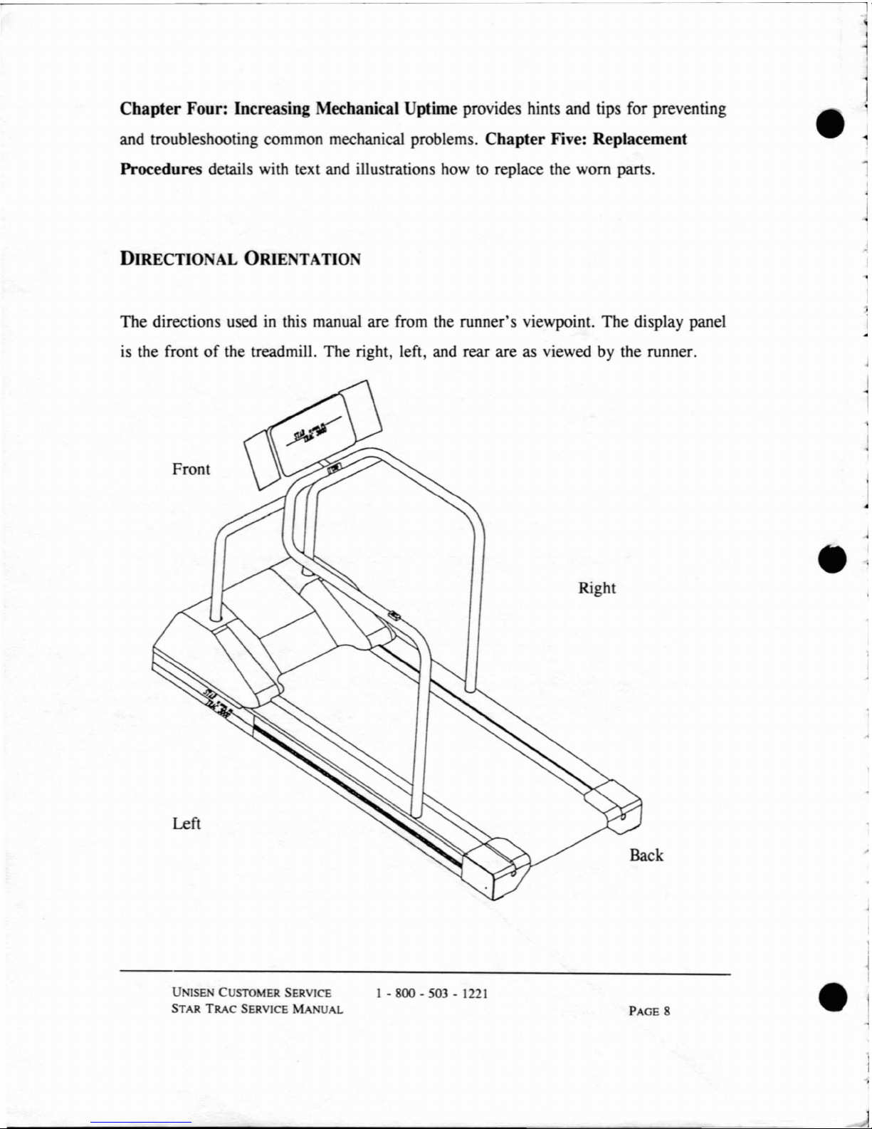
DIRECTIO AL
ORlE
TATIO
The
directions usedinthis manual are from the runner's viewpoint.
The
display panel
is the front
of
the treadmill. The right, left and rear are as viewed by the runner.
•
Front
Left
UNISE
CUSTOMER SERVICE
STAR
TRAC
SERVICE
MA
UAL
I - 800 - 503 -
1221
Right
Back
PAGE 8
•
Page 11
•
CHAPTER
ONE:
PREVENTIVE
MAINTENANCE
•
Performing regular preventive maintenance on all STAR TRAC treadmills is strongly
recommended. Without preventive maintenance, normal wear and tear may cause
cumulative effects, such as misalignment and early replacement
of
parts.Inaddition,
the more the treadmill is
in
use, the stricter you should adheretothe preventive
maintenance schedule.
NOTE:Ifany unusual problems, such as error codes and blown circuit breakers,
occur, please refer to Chapter Three: Troubleshooting Error Codes.
•
UNlSEN
CUSTOMER SERVICE
STAR
TRAC
SERVICE
MANuAL
1 -
800-503-1221
PAGE 9
l~
_
Page 12
DAILY PREVENTIVE MAINTENANCE
You should perform the following maintenance on a daily basis.
• Use a cloth and diluted all-purpose cleaner to remove any dust, dirt,
and other substances from the main
part
of
the treadmill. Wipe the
display panel, console, handrails, and motor cover. Avoid using cleaner
under the running belt.
• To ensure the longevity
of
the running belt, clean under the running
belt with a soft,
dry cloth.
To clean, slide the cloth between the running belt and the deck from
one side
of
the frametothe other side. You may need a rulerorrod to
slide towel under the running belt.
Then, holding the edges
of
the cloth, pull the cloth from the headroller
to the tailroller.
NOTE:
Do
NOT clean the running belt by activating the treadmill. Do
NOT place feet or any weight on the running belt when cleaning the
treadmill.
•
•
UNISEN CUSTOMER SERVICE
STAR
TRAC
SERVICE MANUAL
I - 800 - 503 -
1221
PAGE
10
•
Page 13
You should perform the following maintenanceona weekly basis.
•
•
•
•
•
Check the running belt for alignment and tension.
NOTE: Do NOT automatically tighten the belt daily. For additional
infonnation on how to verify belt alignment
or
correct a belt that has
slipped or mistracked, please refer
to Chapter Four: Increasing
Mechanical Uptime.
Verify power cord is not under the treadmill.Ifthe power cord is
placed under the treadmill, it may become pinched
or
bind up the
elevation screws. This results
in
error codes or treadmill damage.
WEEKL
Y PREVENTIVE MAINTENANCE
Elevate the treadmill and vacuum the floor under the treadmill. Be
careful nottobump the elevation switches as you sweep.
• Inspect the deck and running belt surfaces for unusual wear.
Check the deck for worn areas where the underlying fiber board
or
soft
spots are visible. Inspect the underside center
of
the running belt for a
worn, glazed appearance.
•
UNISEN CUSTOMER SERVICE
STAR
TRAC
SERVICE
MANUAL
1 - 800 - 503 -
1221
PAGE
11
Page 14
•
Walk on the deck surface.Ifany portion feels soft, replace the deck.
NOTE: For information on replacing a worn deck or belt, please refer
to Chapter Five: Replacement Procedures.
•
•
If
you have a 3000 Series, check the subdeck and weardeck screws.
If
loose, tighten them.
BIWEEKLY
PREVENTIVE MAINTENANCE
You should perform the following maintenance biweeklyortwice a month basis.
•
Vacuum around the motor and electronics by removing the shroud
cover and lifting the motor shroud.
Raise the motor shroud and suspend it from the display neck with the
bungie cord, from your STAR TRAC Treadmill Toolkit.
Be sure to
avoid bumping or damaging the RPM disc and sensor, elevation sensor,
limit switches, and wire connections.
NOTE:
To
raise the motor shroud, use the Phillips screwdriver to
remove the screw in the motor shroud. Gently lift the motor shroud
up
the display handrail.
Using
the bungie cord from the STAR TRAC
Toolkit, hold the motor shroud
at the top
of
the display handrail.
•
UNISEN CUSTOMER SERVICE
STAR
TRAC
SERVICE
MANUAL
1 - 800 - 503 -
1221
PAGE
12
•
Page 15
•
To
replace the motor shroud, remove the bungie cord and
Lower
the
motor shroud until it touches the frame. Press the sides
of
the motor
shroud to the frame and attach the
veLcro
fasteners. Using the Phillips
screwdriver, tighten the screw in the center
of
the motor shroud.
MONTHLY
PREVENTIVE
MAINTENANCE
You should perform the following maintenance once a month.
• Lubricate the elevation screws with a silicon lubricant to prevent rust
accumulation.
• Activate Motor Test Mode and Display Test ModeofDiagnostic Test.
This will diagnose any unforeseen maintenance and error codes.
NOTE: For additionaL information on activating Diagnostic Test,
please refer to Chapter
Two:
Diagnostic test.
••
UNISEN CUSTOMER SERVICE
STAR
TRAC
SERVICE
MANUAL
1-
800-503-1221
PAGE
13
Page 16

e.
e·
e
Page 17
r
I
[
I
•
•
--
--
-----------------
CHAPTER Two:
DIAGNOSTIC TEST
The STAR TRAC software program contains a self-diagnostic test mode that precisely
determines the reason for
an
error. This chapter outlines howtoactivate Diagnostic
Test and diagnose the problem.
Diagnostic Test consists
of
the Motor Test Mode and Display Test Mode. You will
use the test mode to check the motor, sensors (if they are working and calibrated),
and switches (if they are active and responding). The Display Test Mode checks the
keyboard response and
Qualityofthe LEDs. The Diagnostic Tests are the best
methods for determining specific failure areas
on
the STAR TRAC treadmill.
Remember,
in
Diagnostic test, you areincommand. Pay attention to the display
panel. The LED lights and readouts show you the exact position and limits
of
the
treadmill.
In
this chapter,
you
will learn:
CONTENTS
ACTIVATING MOTOR TEST MODE
ACTIVATING DISPLAY TEST MODE
PAGE
NUMBER
16
25
•
UNISEN CUSTOMER SERVICE
STAR TRAC SERVICE
MANUAL
1 - 800 -
503
- 1221
PAGE 15
Page 18
ACTIV
ATING
MOTOR TEST MODE
OF
DIAGNOSTIC TEST
Use the Motor Test Modetocheck the motor, sensors (if they are working and
calibrated), and switches (if they are active and responding).
In
addition, you may be
instructed to activate the Motor Test Mode during preventive maintenance
or
troubleshooting.
To activate Motor Test Mode, please follow these instructions.
If
your treadmill does
not respond, please refer
to
Chapter Four: Increasing Mechanical Uptime or
contact STAR TRAC customer service.
•
..
Step One
Tum the power switchtothe OFF position.
Place the treadmill into the Motor Test Mode.
Step Two
•
If
you have a Jogger, Programmable,orSimple with number
keys, simultaneously press key number 8, while turning the
power switch
to
ON.
•
•
If
you have a Walker or Simple with no number keys,
simultaneously press the
- (minus) key, while turning the power
switch
to
ON.
UNISEN CUSTOMER SERVICE
STAR
TRAC
SERVICE MANUAL
1 - 800 - 503 -
1221
PAGE 16
•
Page 19
•
Step Three Verify the display panel reads:
Verify the running belt
is
not moving.
•
If
you have a 2000 Series treadmill from 1990orearlier, verify
the display panel reads:
If
the running beltisnot moving, proceed to the next step.
If
the running belt begins moving, then:
•
To
raise the motor shroud, use the Phillips screwdriver
to remove the screw holding the motor shroud to the
frame. Gently raise the motor shroud up the display
handrail.
Using
the bungie cordfrom the STAR TRAC
Toolkit, hold the motor shroud at the top
of
the display
handrail.
I
J
r
•
Step Four
o
o
3
2
0.0
0.0
UNISEN
CUSTOMER SERVICE
STAR
TRAC
SERVICE
MANUAL
1 - 800 - 503 - 1221
PAGE 17
Page 20
•
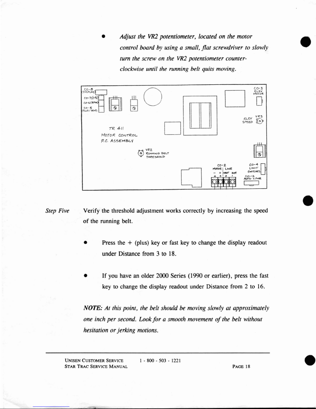
Adjust the
VR2
potentiometer, located on the motor
control board by using a small, flat screwdriver to slowly
tum
the screw on the
VR2
potentiometer counter-
clockwise until the running belt quits moving.
•
TR
4/1
JV1oroR.
CONTRoL
p.C.
ASSEMBL'{
rn
D
L-.-..----J
D
(,0-3
ELE"
"""OTOR.
o
o
co-2.
>1aTl>'t
I
L,,,e
- +.....,...
"dT
..
2 I
CO-4D
L'
.....
'l
S"'''!l:1l!£
c.o-\2.
AurD·'J,.F
.....
1it
C::::J
•
Step Five Verify the threshold adjustment works correctly by increasing the speed
of
the running belt.
• Press the
+ (Plus) key
or
fast key to change the display readout
under Distance from 3 to 18.
•
If
you haveanolder 2000 Series (1990orearlier), press the fast
key to change the display readout under Distance from 2 to 16.
NOTE:
At
this point, the belt should be moving slowly at approximately
one inch per second. Look
forasmooth.
movementofthe belt without
hesitation orjerking motions.
UN1SEN CUSTOMER SERVICE
STAR
TRAC
SERVICE
MANUAL
1 - 800 - 503 -
1221
PAGE
18
•
Page 21
•
•
If
The
belt doesn't move or moves too fast, then adjust the
belt speed.
• Adjust the
VR2
potentiometer, located on the
motor control board by using a small, flat
screwdriver.
To
increase the running belt speed, carefully
tum
the screw clockwise.
To
decrease
The
running belt speed, carefully
tum
the
VR2
screw counter-clockwise.
• Verify the running beltismoving at approximately
one inch per second.
• Replace the motor shroud by removing
The
bungie
cord and lowering the motor shroud until
it
TOuches
the frame. Press the sidesofthe motor
shroud to the frame and attach the velcro
fasteners.
Using
the Phillips screwdriver, tighten
the screw
in the centerofthe motor shroud.
•
UNISEN
CUSTOMER SERVICE
STAR
TRAC
SERVICE
MANUAL
1 - 800 - 503 -
1221
PAGE
19
Page 22
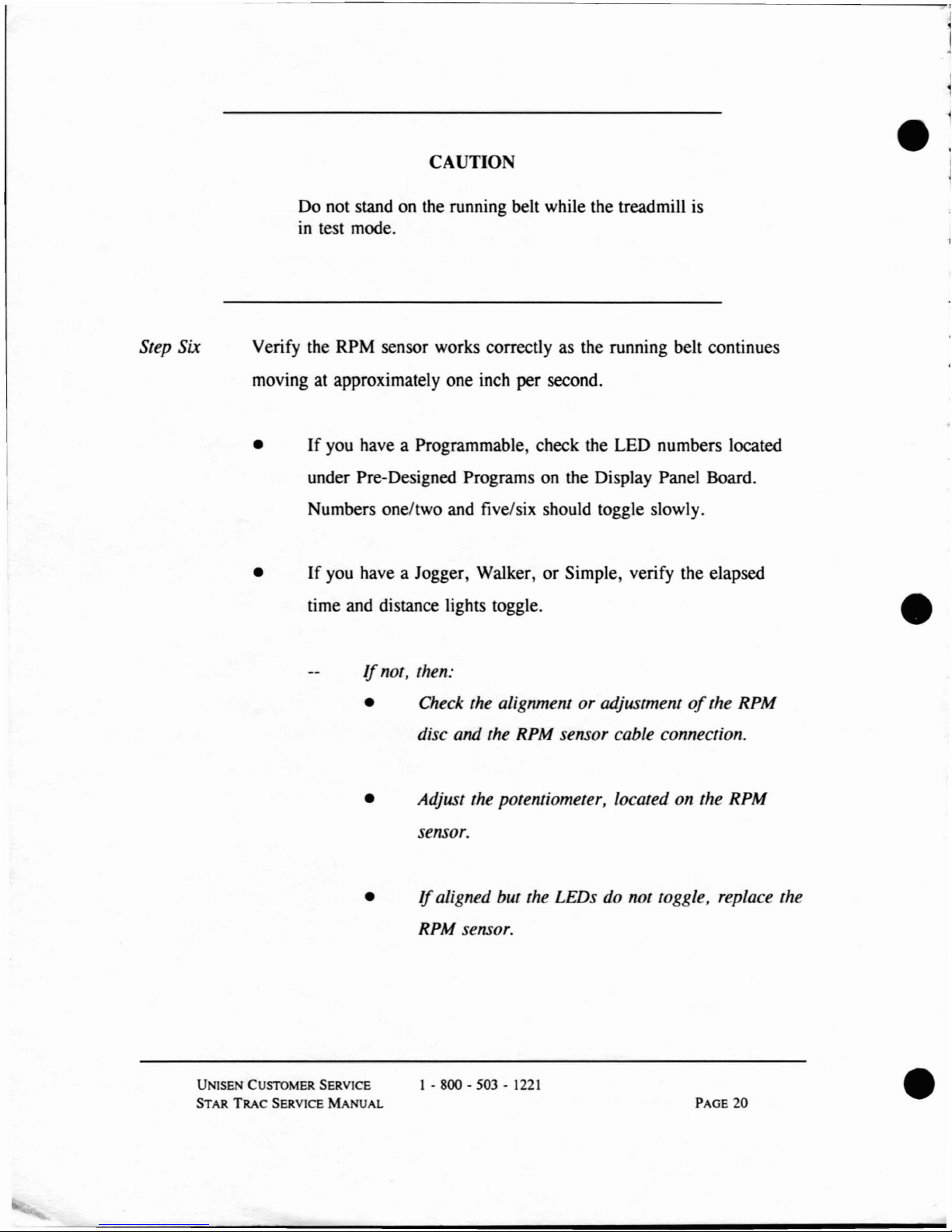
Step Six
CAUTION
Do not stand on the running belt while the treadmill is
in
test mode.
Verify the RPM sensor works correctly as the running belt continues
moving at approximately one inch per second.
•
If
you have a Programmable, check the LED numbers located
under Pre-Designed Programs on the Display Panel Board.
Numbers one/two and five/six should toggle slowly.
•
•
If
you have a Jogger, Walker,orSimple, verify the elapsed
time and distance lights toggle.
If
not, then:
• Check the alignment
or
adjustmentofthe RPM
disc and the RPM sensor
cabLe
connection.
• Adjust the potentiometer, Located on the RPM
sensor.
•
If
aligned but the LEDs do not toggLe,
repLace
the
RPM sensor.
•
UNISEN CUSTOMER SERVICE
STAR
TRAC
SERVICE MANUAL
1 - 800 - 503 -
1221
PAGE
20
•
Page 23
•
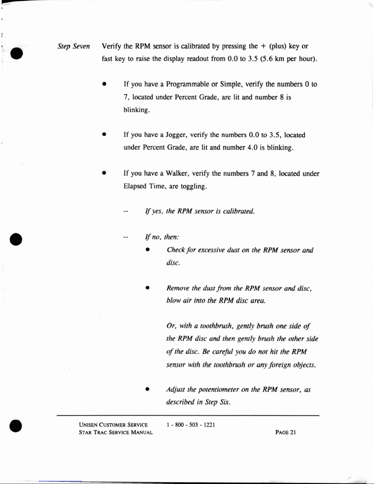
Step Seven Verify the RPM sensor is calibrated by pressing the + (Plus) key
or
fast key to raise the display readout from
0.0
to 3.5 (5.6
km
per hour).
•
If
you have a ProgrammableorSimple, verify the numbers 0 to
7, located under Percent Grade, are lit and number 8 is
blinking.
•
If
you have a Jogger, verify the numbers
0.0to3.5,
located
under Percent Grade, are lit and number
4.0
is blinking.
•
If
you have a Walker, verify the numbers 7 and 8, located under
Elapsed Time, are toggling.
If
yes, the RPM sensoriscalibrated.
If
no, then:
• Check for excessive dust on the RPM sensor and
disc.
• Remove the dust from the RPM sensor and disc,
blow air into the RPM disc area.
Or,
with a toothbrush, gently brush one side
of
the RPM disc and then gently brush the other side
of
the disc.
Be
careful youdonot hit the RPM
sensor with the toothbrushorany foreign objects.
• Adjust the potentiometer on the RPM sensor,
as
describedinStep Six.
•
UNISEN CUSTOMER SERVICE
STAR TRAC SERVICE
MANUAL
1 - 800 - 503 -
1221
PAGE
21
Page 24
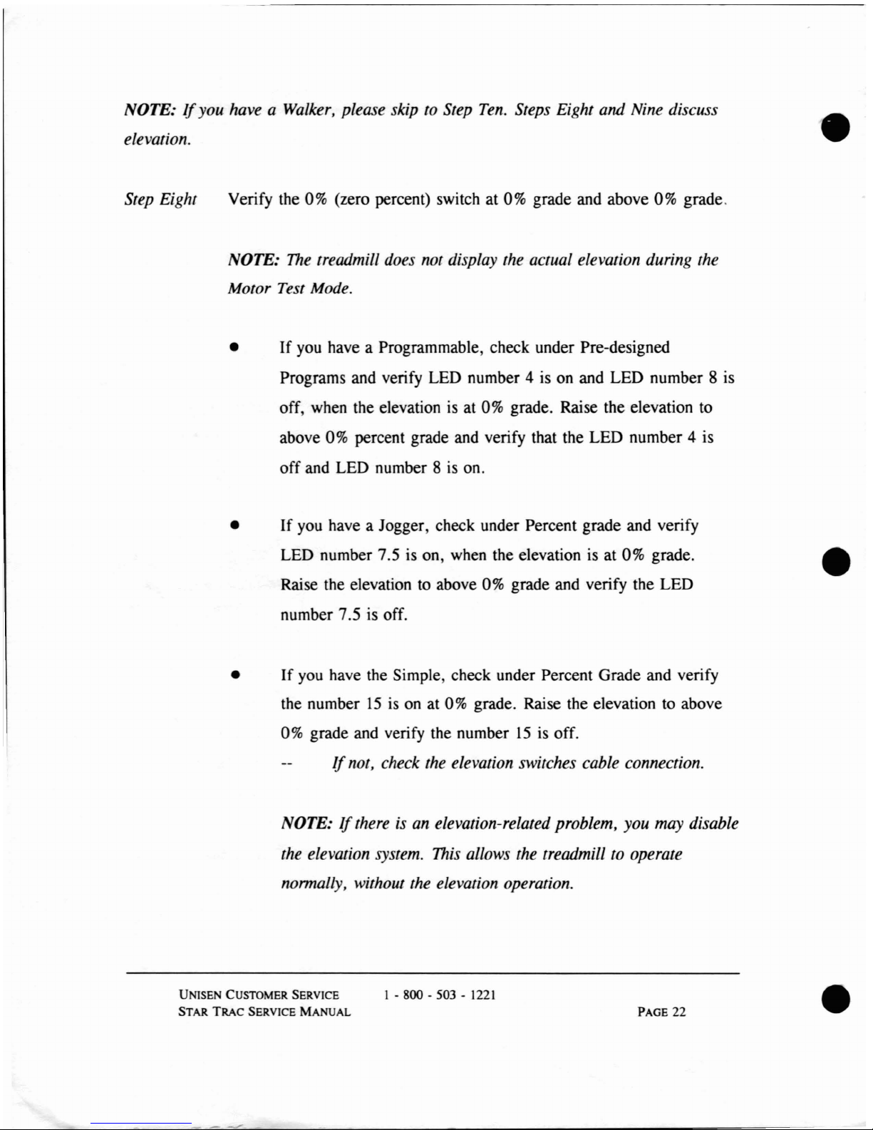
NOTE:Ifyou have a Walker, please skiptoStep
Ten.
Steps Eight and Nine discuss
elevation.
•
Step Eight
Verify the 0% (zero percent) switch at 0% grade and above 0% grade.
NOTE:
The
treadmill does not display the actual elevation during the
Motor Test Mode.
•
If
you have a Programmable, check under Pre-designed
Programs and verify LED number 4 is on and LED number 8 is
off, when the elevation is at 0% grade. Raise the elevation to
above 0% percent grade and verify that the LED number 4 is
off and LED number 8
is
on.
•
If
you have a Jogger, check under Percent grade and verify
LED number 7.S is on, when the elevation is at 0% grade.
Raise the elevation to above
0%
grade and verify the LED
number 7.5 is off.
•
•
If
you have the Simple, check under Percent Grade and verify
the number
15ison at
0%
grade. Raise the elevation to above
0% grade and verify the number
15isoff.
If
not, check the elevation switches cable connection.
NOTE:
If
thereisan
elevation-related problem, you may disable
the elevation system.
This
allows the treadmill to operate
nonnaLLy,
without the elevation operation.
UNISEN CUSTOMER SERVICE
STAR
TRAC
SERVICE
MANUAL
1 - 800 - 503 -
1221
PAGE 22
•
Page 25
p
r
l
•
l
•
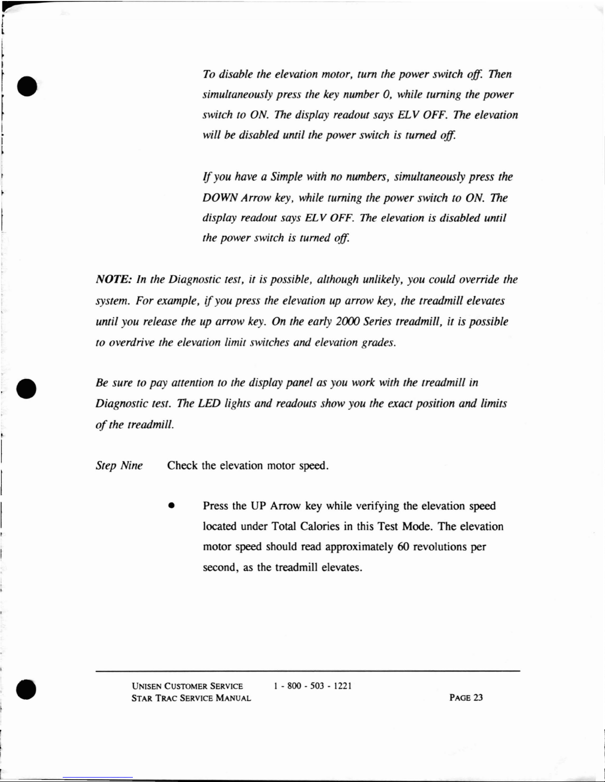
To
disabLe
the eLevation
mOlor,
turn the power switch off. Then
simuLtaneousLy press the key number 0, while turning the power
switch
to ON.
The
dispLay
readoUl
says ELV OFF. The eLevation
will be disabLed until the power switch is turned off.
Jfyou
have a Simple with no numbers, simultaneously press the
DOWN Arrow key, while turning the power switch
to ON. The
dispLay
readout says ELV
OFF.
The
eLevation is disabLed until
the power switch is turned off.
NOTE:
In
the Diagnostic test, it is possibLe, aLthough unlikeLy, you could override the
system. For exampLe,
if
you press the elevation up arrow key, the treadmill elevates
until you release the up arrow key. On the early 2000 Series treadmill, it is possible
to overdrive the elevation
Limit
switches and eLevation grades.
Be sure
to pay attention to the display panel as you work with the treadmill in
Diagnostic test. The
LED
Lights
and readouts show you the exact position and
Limits
of
the treadmill.
Step Nine
Check the elevation motor speed.
• Press the UP Arrow key while verifying the elevation speed
located under Total Calories
in
this Test Mode. The elevation
motor speed should read approximately 60 revolutions per
second, as the treadmill elevates.
•
UNISEN CUSTOMER SERVICE
STAR
TRAC
SERVICE
MANUAL
1 - 800 - 503 -
1221
PAGE
23
Page 26
•
Press the DOWN Arrow
key
while verifying the elevation speed
located under Total Calories
in
this Test Mode. The elevation
motor speed should read approximately 60 revolutions per
second or higher, as the treadmill descends.
If
not, then:
• Adjust
VR3
on the Motor Control Board.
To
increase the speed,
tum
VR3
clockwise.
To
decrease the speed,
tum
VR3
counter-clockwise.
If
yes, proceed to the next step.
If
the display numbers aren't reading, check the elevation
sensor connection.
•
Step
Ten
If
an error code appears,
tum
the power switch to
OFF.
Wait
four seconds, then
tum
the power switch to
ON.
Replace the motor shroud by removing the bungie cord and lowering
the motor shroud until it touches the frame. Press the sides
of
the
motor shroud
to
the frame and attach the velcro fasteners. Using the
Phillips screwdriver, tighten the screw
in
the centerofthe motor
shroud.
•
Step Eleven Exit the Motor Test Mode by pressing the STOP key.
• Tum the power switch
to
OFF. Wait four seconds, then tum the
power switch
to
ON.
UNISEN CUSTOMER SERVICE
STAR
TRAC
SERVICE
MANUAL
1 - 800 - 503 -
1221
PAGE
24
•
Page 27
•
ACTIVATING DISPLAY
TEST
MODE
OF DIAGNOSTIC
TEST
Use the Display Test Modetocheck the display panel, key response, and quality
of
the LEDs. In addition, you may be instructed to activate the Display Test Mode
during preventive maintenance
or
troubleshooting.
To activate Display Test Mode, please follow these instructions:
Step One
Step
Two
Tum
the power switch to the OFF position.
Place the treadmill into Display Test Mode.
•
If
you have a Programmable, Walker,orSimple with number
keys, simultaneously press the key number 5, while turning the
power switch to ON.
•
•
If
you have a JoggerorSimple with no number keys,
simultaneously press the
+ (Plus) key, while turning the power
switch to ON.
NOTE:Ifyou cannot access Display Test Mode, you may need to
replace the display panel. For addifional injonnafion on
troubleshooting the display panel, please refer
to Chapter Three:
Troubleshooting
Error
Codes.
•
UNISEN
CUSTOMER SERVICE
STAR
TRAC
SERVICE
MANUAL
1 - 800 - 503 -
1221
PAGE 25
Page 28
Step Three All the LEOs on the Display Panel should be lit. Press any key, except
the STOP key, to display the EPROM number.
• Please make note
of
this EPROM number.Ifthere are problems
with the display panel, STAR TRAC requires this EPROM
number to ship the correct replacement part.
•
Step Four
Step Five
Check the key response by individually pressing each key on the
display panel. Each key should beep and display a pattern
of
LED
lights on the display panel readout. The 0 key will beep, but no LED
lights will
be displayed.
If
not all the LEDs to form the pattern are lit, you may need to
replace the display panel. For additional information, please
refer
to Chapter Three: Troubleshooting Error Codes.
Exit the Display Test Mode.
• Press the STOP key.
• Tum the power switch to OFF. Wait four seconds, then tum the
power switchtoON.
•
UNlSEN CUSTOMER SERVICE
STAR TRAC SERVICE
MANUAL
5
I - 800 - 503 -
1221
PAGE
26
•
Page 29
•
•
CHAPTER
THREE:
TROUBLESHOOTING ERROR CODES
This chapter outlines the speed, CPU elevation, and FS (fail safe) error codes and
howtosolve
the
error
code
problems.
To correct an error using this troubleshooting guide, locate the typeoferror code,
such as
SPD
ER 2, and follow the instructionsinthe flow charts.Ifthe error persists
continue to the next step and follow the instructions and so on.
In
this chapter, you will learn error codes for:
•
CONTEIVTS
SPEED
(SPD
ER)
ELEVATION
(EL
ER)
FAIL
SAFE
(FS ER)
CPU (CPU ER) ERROR
No
DISPLAY POWER
UNISEN CUSTOMER SERVICE
STAR
TRAC
SERVICE
MA
UAL
1 - 800 - 503 -
1221
PAGE NUMBERS
28
38
52
55
57
PAGE
27
Page 30
SPEED
(SPD
ER)
ERROR CODES
Speed (SPD ER) error codes indicate that the RPM sensor may be damaged or the
CPU circuit is being interrupted, such
as
a ground problem or loose connection.
The following flow charts demonstrate the corrective steps for speed error codes 0,
1,
2, and 3. Begin these instructions by placing the treadmillinthe Motor Test Mode.
To enter Motor Test Mode, simultaneously press the 8 key, while turning the power
switch to ON.
If
you have a Simple with no number keys, simultaneously press the -
(minus) key, while turning the power switch to ON.
•
The display panel should read:
or
on older models:
o
o
3
2
0.0
0.0
NOTE: Please begin by cleaning dust and obstructions from the RPM disc and RPM
sensor.
•
UNISEN CUSTOMER SERVICE
STAR
TRAC
SERVICE
MANUAL
1 - 800 - 503 -
1221
PAGE
28
•
Page 31
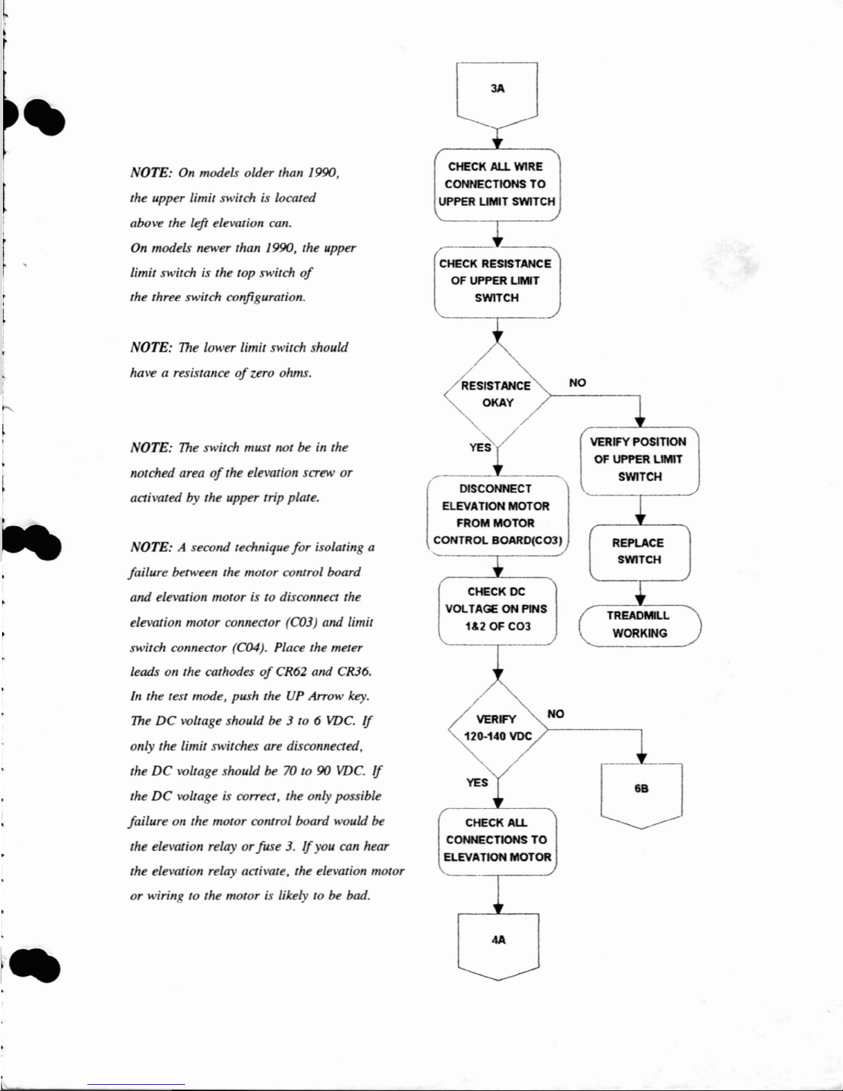
OTE:
On
models older than 1990,
the upper limit switch is located
above the left elevation can.
On
models newer than 1990, the upper
limit switch is the top switch
of
the three switch configuration.
NOTE: The lower limit switch should
have a resistance
of
zero ohms.
OTE: The switch must not be
in
the
notched area
of
the elevation screw or
activated by the upper trip plate.
OTE: A second technique
for
isolating a
failure between the motor colltrol board
and elevation motor is to disconnect the
elevation motor connector (C03)
and limit
switch connector (C04). Place the meter
leads on the cathodes
of
CR62 and CR36.
In
the test mode, push theUPArrow key.
The
DC
voltage should be 3 to 6 VDe.
If
only the limit switches are disconnected,
the
DC
voltage should be 70 to90VDe.
If
the
DC
voltage is correct, the only possible
failure on the motor colltrol board would be
the elevation relay
or
fuse 3.Ifyou can hear
the elevation relay activate, the elevation motor
or wirin to the motor is likely to be bad.
]A
CHECK ALL WIRE
CONNECTIONS
TO
UPPER
UMIT
SWITCH
CHECK RESISTANCE
OF UPPER LIMIT
SWITCH
~SISTANCE
~
OKAY
YES /
[
DISCONNECT
ELEVATION
MOTOR
FROM MOTOR
CONTROL
BOARD(COJ)
CHECK DC
VOLTAGEONPINS
1&2 OF
C03
NO
CHECK
ALL
CONNECTIONS
TO
ELEVATION
MOTOR
4A
NO
VERIFY POSITION
OF
UPPER LIM1T
SWITCH
REPLACE
SWITCH
TREADMILL
WORKING
6B
Page 32
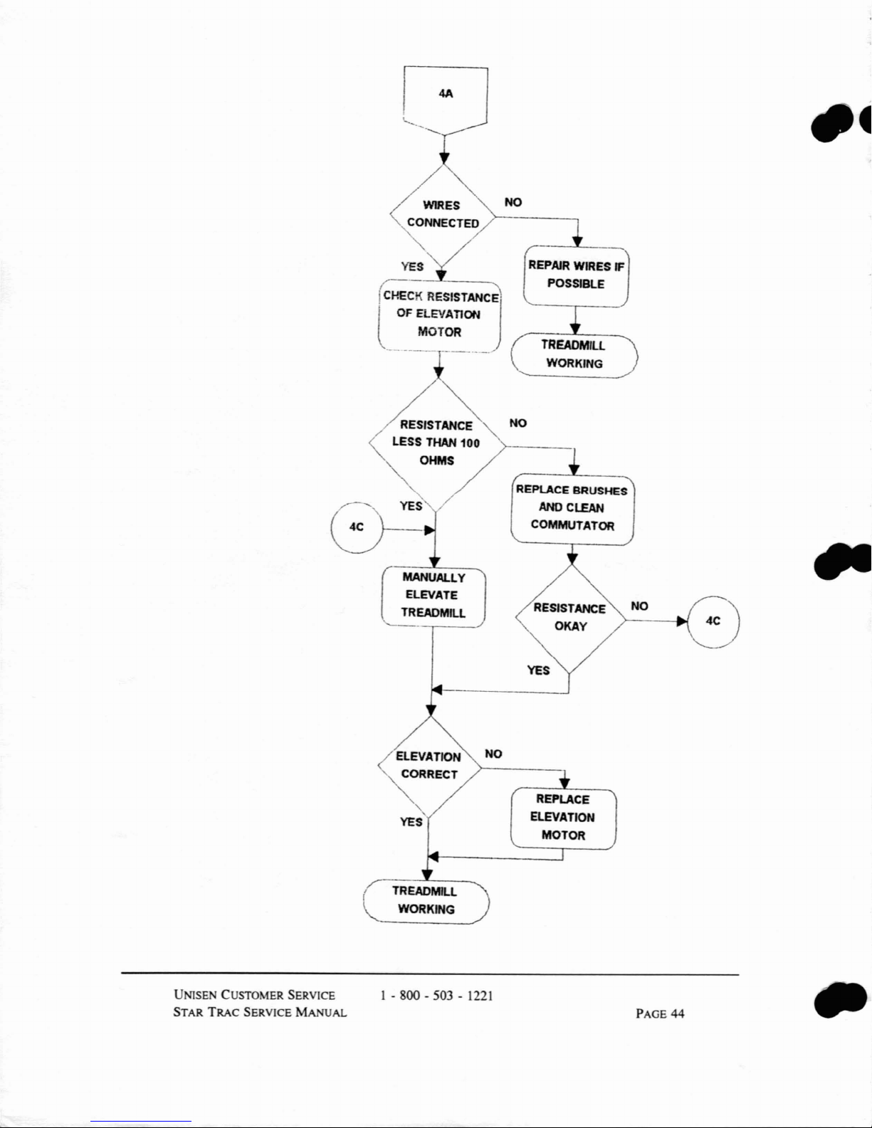
o
~
•
~ES
<CO:ECTED
YES
C-
!
CHECK
l
cr
RESISTANCJE'
OF
ELEVATION
MOTOR
-----
RESISTANCE
LESS THAN
OHMS
UALLY
ELEVATE
TREADMIU
_._--
100
NO
REPAIR
POSSIBLE
TREADMIll
WORKING
NO
REPlACE
ANoC~
COMMUTATOR
WIRES
IF
BRUSHES
UNISE CUSTOMER SERVICE
STAR
TRAC
SERVICE MANUAL
TREADMILL
WORKING
1 - 800 - 503 -
1221
NO
REPLACE
ELEVATION
MOTOR
PAGE
44
Page 33

NOTE:
On
models older than 1990,
the
0% switch is located next to the
lower limit switch under the treadmill.
On
models newer than 1990, the 0%
switch is the bortom switchofthe
three switch configuration.
NOTE:
The
0% switch should have a
resistance
of
infinite ohms at 0%
and 0 ohms above 0%.
UNISEN
CUSTOMER SERVICE
STAR
TRAC
SERVICE
MANUAL
5A
CHECK
All
WIRE
CONNECTIONS
TO
ZERO PERCENT
SWITCH
CHECK RESISTANCE
OF
ZERO PERCENT
SWITCH
RESISTANCE
OKAY
REPLACE
SWITCH
TREADMill
WORKING
1 - 800 - 503 -
1221
YES
RECHECK ALl
WIRES
PAGE
45
Page 34
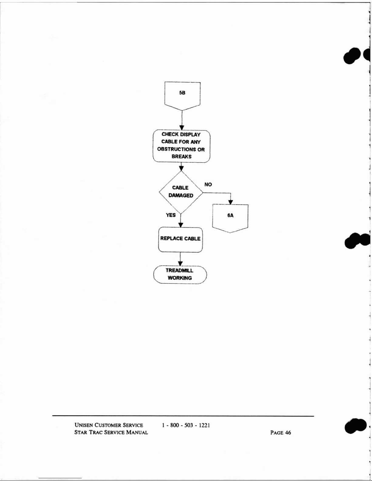
58
CHECK
DISPLAY
CABLE
FOR
ANY
OBSTRUCTIONS
OR
BREAKS
J
j
CABLE
DAMAGED
NO
6A
UNlSEN CUSTOMER SERVICE
STAR
TRAC
SERVICE MANUAL
REPLACE
CABLE
TREADMILL
WORKING
1 - 800 - 503 -
1221
PAGE
46
Page 35

•
OTE: Simultaneously press the key
number 5 (on Simples without number
keys, press the + (plus) key), while
turning the power switch to
ON.
UNlSEN CUSTOMER SERVICE
STAR
TRAC
SERVICE MANUAL
6A
ENTER DISPLAY
TEST
MOOE
/
//
/ KEYS
RESPOND
~-~
("
REPLACE
t,
FACEPLATE
--,-
TREADMILL
WORKING
I -
gOO-503-1221
YES
OOONNECT
DISPlAY
CABLE
ON MOTOR
CONTROL AND
DISPLAY BOARD
IF
ERROR CONTINUES,
REPLACE DISPLAY
CABLE
AND/OR DISPlAY
BOARD
PAGE
47
Page 36

For older models:
NOTE: For transfonner with resistor:
red/white
black/white
red/black
red/white
black/white
red/black
= approx. J6 ohms
= approx. 4 ohms
= approx. J3 ohms
= approx. 4. 7 ohms
= approx.
2.
7 ohms
= approx.
2.3
ohms
68
~
-"
CHECK RESISTANCE
AUTOT':SFOR_
J
NO
REPLACE AUTO
TRANSFORMER
TREADMILL
WORKING
YES
REPlACE
MOTOR
CONTROL
80ARD
..
NOTE:Ifthe elevation error cominues, disable the elevation circuit by turning the power switch to
OFF.
Wait
four
seconds, then simultaneously press the key number 0
(on
Simples without number keys,
press the
DOWN
Arrow key), while turning the power switchtoON.Toenable the elevation circuit,
turn the
power
switch to
OFF.
UNISEN CUSTOMER SERVICE
STAR
TRAC
SERVICE
MANUAL
1 - 800 - 503 -
1221
PAGE
48
.,
Page 37

NOTE:
To
ellter Motor Test Mode,
please
refer to the instructions
on page 38.
ELEVATION
ERROR 2
( ENTER TEST
MODE
ELEVATE TREADMILL.,
THEN DOWN
TO
ZERO
LEVEL
SPEED
NO
CORRECT
>------------,
PAGE
49
ADJUST
VR3
ON
MCB
TO
THE
CORRECT SPEED
GOTOELEV.
ERROR 1 OR 3
FLOWCHART
1A
NO
~EVATES
TREADMILL
WORKING
RESET
TREADMIlL
BY
TURNING POWER
SWITCH OFF THEN
ON
CHECK ELEVATION
MOTOR
SPEED WHILE
MOTORISOPERATING
I - 800 - 503 -
1221
UNlSEN CUSTOMER SERVICE
STAR
TRAC
SERVICE
MANUAL
NOTE:Inthe test mode, the
correct Speed is displayed
uruler Elapsed
Time.
NOTE:
VR3islocated on the
right cellter
of
the motor
control board.
NOTE: When ascending, the
elevation speed should be
between
55
and 60.
When
desceruling, the speed should
befaster than
60.
Page 38

FAIL SAFE (FS
ER)
ERROR CODE
Fail safe (FS ER) error codes are caused by shorted or faulty keys on either the
display panel
or
the emergency stop switch.
The following flow charts demonstrate the corrective steps for fail safe error codes 1
and 2. Begin these instructions by placing the treadmill
in
Display Test Mode.
NOTE:Ifthe
FS
Error Code occurs when you are entering Motor Test Mode, you
may
have pressed the wrong key number. Confinn the typeofSTAR TRAC treadmill
(programmable, simple, jogger,
or
walker) and verify the key number. Re-enter test
mode.
Begin these instructions by placing the treadmillinthe Display Test Mode.
To
enter
Display Test Mode, simultaneously press the key number 5, while turning the power
switch to the ON.
If
you have a Simple without number keys, simultaneously press
the
+ (Plus) key while turning the power switch
to
the ON.
--
UNISEN CUSTOMER SERVICE
STAR
TRAC
SERVICE
MANUAL
1 - 800 - 503 - 1221
PAGE
50
Page 39

TREADMILL
WORKING
•
FS ERROR 1
TURN POWER SWITCH
TO
-OFF-
WAIT 2 I
SECONDS THEN
TUR
TO-OW
INPUT
ANY
I
INSTRUCTiON I
ERROR
CODE
~O
_
CONTIN7
YES
ENTER DISPLAY
TEST
MODE
YES
•
OTE:
To
ellter Display
Test
Mode,
please refer to the instructions
on
page 50.
(
PRESS
EACH
KEY,
THE
DISPLAY
BEEPS
AND CHANGES
CHANGE
FACEPLATE
NO
REPLACE FACE
PLATE
OR
DISPLAY
ASSEMBLY
TREADMILL
WORKING
•
UNISEN CUSTOMER SERVICE
STAR
TRAC
SERVICE
MANUAL
TREADMIlL
WORKING
1 - 800 - 503 -
1221
PAGE 51
Page 40

NOTE:
To
enter Display
Test
Mode,
please refer to the instrucriollS
on page 50.
UNISE CUSTOMER SERVICE
STAR
TRAC
SERVICE
MANUAL
FS ERROR 2
DISCONNECT
EMERGENCY
STOP
SWITCH FROM BACK
OF DISPLAY BOARD
CONNECT
2 PINS ON
DISPLAY
BOARD
TOGETHER USING A WIRE
OR PAPER CLIP
ENTER DISPLAY
TEST
MODE
REPLACE
DISPLAY BOARD
TREADMIlL
WORKING
1 - 800 - 503 -
1221
REPLACE
REMOTE
STOP SWITCH
AND/OR
CABLE
PAGE
52
•
•
•
Page 41

•
•
CPU
(CPU
ER)
ERROR
CODES
The CPU (CPU ER) error codes indicate the CPU (central processing unit) circuit is
being interrupted by a ground problem, loose connection, or static noise.
The following flow chart demonstrates the corrective steps for all CPU error codes.
CAl.mON
Always unplug the STAR TRAC treadmill from the power outlet,
prior
to
troubleshooting.
(
OFF/ON POWER
SWITCH CYCLED TOO
FAST
[
URN
POWER
SW'9CH'
TO
-OFF-
WAIT 2
SECONDS THEN TURN
TO
-ON-
/
/CPU
ERROR
" CONTINUES
"
NO
YES
1A
•
UNISEN CUSTOMER SERVICE
STAR TRAC SERVICE
MANUAL
TREADMIll
"")
WORKING
./
1 - 800 - 503 - 1221
PAGE
53
Page 42
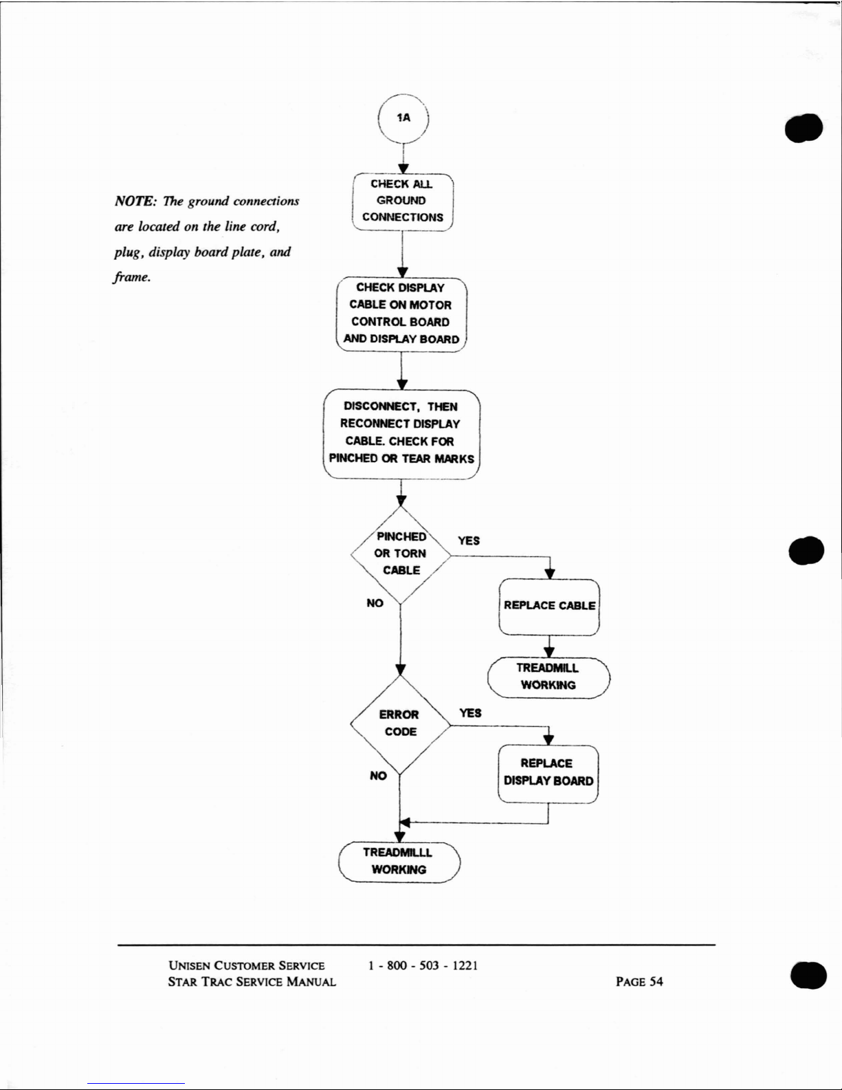
NOTE:
The
ground connections
are located on the line cord,
plug, display board plate,
and
frame.
G
r
I
CHECK
AU.
GROUND
\.. CONNECTIONS
CHECK
DISPlAY
CABLE ON MOTOR
CONTROl. BOARD
AND
DISPlAY
BOARD
DISCONNECT. THEN
RECONNECT DISPLAY
CABLE. CHECK
FOR
PINCHED
OR
TEAR
MARKS
•
NO
YES
YES
REPLACE CABLE
TREADMILL
WORKING
•
NO
REPLACE
DISPlAYBOARD
UNlSEN CUSTOMER SERVICE
STAR
TRAC
SERVICE
MANuAL
TREADMlU.L
WORKING
1 - 800 - 503 - 1221
PAGE
54
•
Page 43

•
•
No
DISPLAY
POWER
When the power switch is turned to ON, you should be able to read the display.
If
not, begin by visually inspecting the treadmill, wall circuit breaker and power
switch.
UNISEN CUSTOMER SERVICE
STAR
TRAC
SERVICE MANUAL
1 - 800 - 503 -
1221
PAGE
55
Page 44

NOTE:
The
flat ribbon cableisconnected
to
the venical connection.
The
round cable
is connected to the horizolltal connection.
OTE:
The
REG 2 is located 011 the upper left
of
the motor colltrol board. Place the red lead
of
the meter on the left sideofREG 2 and black
lead on the center groulld
serl!}
.
NO DISPLAY
POWER
VERIFY WALL CIRCUIT
BREAKER IS ON,
TREADMIUISPLUGGED IN
AND
POWER SWITCH IS ON
VERIFY
AC
INPUT
VOLTAGE AT PINS
1 & 2
OF CO-2 ON MOTOR
CONTROL BOARD
----~
VERIFY DISPLAY
CABLE IS PLUGGED
IN
TO
CORRECT
CONNECTOR
(CO-8)
VERFY
8VDC ON
REG 2
VERIFY 8VOC ON
REG1
•
•
UNlSE
CUSTOMER SERVICE
STAR
TRAC
SERVICE
MANUAL
2A
1 - 800 - 503 -
1221
NO
REPLACE MOTOR
CONTROL BOARD
TREADMI.l.
WORKING
PAGE 56
•
Page 45
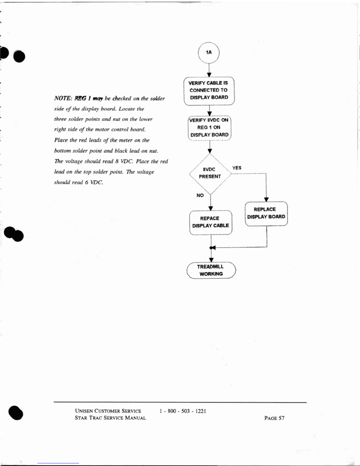
REPACE
DISPLAY CABLE
VERIFY 8VDC ON
REG
1
ON
DISPLAY BOARD
..
OTE:
RE6
J
"'l1Y
be checked on the solder
side
of
the display board. Locate the
three solder poillts and nut on the lower
right side
of
the motor control board.
Place the red leads
of
the meter on the
bottom solder point and black lead on nut.
The
voltage should read 8
VDC.
Place the red
lead on the top solder poillt.
The
voltage
should read
6
VDC.
VERIFY CABLE IS
CONNECTED
TO
DISPLAY BOARD
/ 8VDC
PRESENT
TREADMILL
WORKING
YES
)>---_.--,
REPlACE
DISPLAY BOARD
•
U ISE CUSTOMER SERVICE
STAR
TRAC
SERVICE
MANUAL
1 - 800 - 503 -
1221
PAGE
57
Page 46
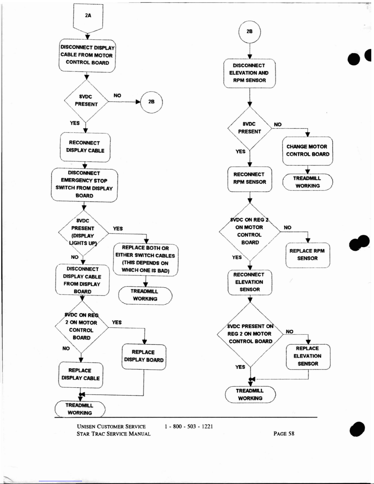
2A
DISCONNECT DISPLAY
CABLE FROM MOTOR
CONTROL BOARD
DISCONNECT
ELEVATION AND
RPM SENSOR
REPLACE
ELEVATION
SENSOR
TREADMl..L
WORKING
CHANGE
MOTOR
CONTROL BOARD
NO
YES
RECONNECT
RPM SENSOR
8VDC PRESENT
REG 2 ON MOTOR
CONTROL BOARD
REPlACE
DISPLAY BOARD
NO
YES
RECONNECT
DISPLAY CABLE
REPlACE
DISPLAY
CABLE
DISCONNECT
EMERGENCY STOP
SWITCH FROM
DISPlAY
BOARD
ON
REG
ON
MOTOR
NO
YES
CONTROl.
-
BOARD/
REPlACE
BOTH
OR
REPLACE RPM
NO
EITHER SWITCH CABLES
YES
SENSOR
(THIS DEPENDS
ON
(
DISCONNECT
WHICH ONE IS BAD)
RECONNECT
DISPLAY CABLE
ELEVATION
FROM
DISPLAY
SENSOR
BOARD
TREADMILL
WORKING
TREADMILL
WORKW<;
UNISEN CUSTOMER SERVICE
STAR
TRAC
SERVICE
MANUAL
1 - 800 - 503 -
1221
TREADMLL
WORKWG
PAGE
58
•
Page 47
..
CHAPTER FOUR:
INCREASING MECHANICAL UPTIME
This chapter describes simple preventive maintenance guidelines that increase
treadmill uptime and reduce mechanical downtime.
In
this chapter, you will troubleshooting of:
CONTENTS
RUNNING
BELT
DRIVE
MOTOR
HEAD-
AND TAILROLLER
TREADMilL
VmRA
TIO
TREADMILL
STATIC
AND SHOCKING
PAGE
NUMBERS
62
65
68
69
71
•
UNISE CUSTOMER SERVICE
STAR
TRAC
SERVICE
MANuAL
1 - 800 - 503 -
1221
PAGE
59
Page 48
RUNNING BELT TROUBLESHOOTING
For
optimal performance during the lifetimeofthe treadmill, running belt adjustments
may become necessary. All adjustments are performed by turning the tailroller
adjustment with a one-quarter inch Allen wrench.
To
troubleshoot your running belt before any problems occur, you may verify the
running belt is properly adjusted and working smoothly by performing the following
four steps:
Step One
Step
Two
Place your hand under the middleofthe running belt. You
should not feel any glaze.
If
the undersideisglazed, replace the running belt.
Elevate the treadmill to the maximum grade. Then, without
electronically activating the running belt, stand at the top
of
the
running belt and gently push
off
from the front handrail. You
should be able to coast
to
the bottomofthe treadmill.
If
you are not able to coast to the boltom, check the wax
glaze, belt tension, and wax build
up
on the tailroller.
If
okay, replace the running belt.
UNISEN CUSTOMER SERVICE
STAR
TRAC
SERVICE
MANUAL
1 - 800 - 503 -
1221
PAGE
60
•
Page 49

Step Three
Activate the running belt electronically. Stand at the backofthe
treadmill and visually inspect the running belt. The running belt
should move smoothly, without drifting from side to side.
If
the running beltisnot moving smoothly or is drifting
from side to side, check the belt tracking as outlined in
Running Belt
Tracking
in this section.Ifokay, replace
the
running belt.
To
replace the running belt, please
refer
to Chapter Five: Replacement Procedures.
..
If
you observe the following symptoms, then the running belt must be replaced:
• Blown breaker after short use.
• Slipping continues after tighten tailroller tension.
• Edges
of
running belt fraying.
• Seam
of
running belt pulling apart.
• Middle
of
running belt folding.
NOTE:Ifyour running belt requires replacement, contact Unisen.
Be
sure to have
your model number and serial number handy.
For
instructions on replacing a running
belt, please refer to Chapter Five: Replacement Procedures.
•
UNISEN CUSTOMER SERVICE
STAR
TRAC
SERVICE
MANUAL
1 - 800 - 503 -
1221
PAGE 61
Page 50
If
the running belt is moving from side to side, the tracked may require adjusting.
Please use the following steps.
NOTE: Turning the bolts as little as one-quanerofa bolt may have substantial effect.
The
best tracking position is
114"to112"
(6mm
to 12mm) from the headroller pulley.
If
your running belt is tracking to the right, then adjust
the running belt to track to the left. Loosen the left
tailroller bolt by turning counter-clockwise
or
tighten the
right tailroller bolt by turning clockwise.
Verify the running belt tracking. Continue adjusting, as
necessary, by turning the tailroller bolt one quarter at a time.
•
RUNNING
BELT
TRACKING
Adjust the tracking by turning the tailroller bolt one quarter tum
at a time.
•
If
your running belt is tracking to the left, then adjust the
running belt to track
to
the right. Tighten the left
tailroller bolt by turning clockwise
or
loosen the right
tailroller bolt by turning counter-clockwise.
Step
Two
Step One
UNISEN CUSTOMER SERVICE
STAR
TRAC
SERVICE
MANUAL
1 - 800 - 503 -
1221
PAGE
62
•
Page 51

•
RUNNING BELT SLIPPAGE
AND
TENSION
The running belt tension
may
needtobe adjusted over time to keep the running belt
from slipping each jogging step or at high speed.
An easy method for testing belt
slippage, before it becomes a problem
is
as follows:
•
Step One
Step
Two
Step Three
Accelerate the running beltto2 mph.
Stand at the side
of
the treadmill. Grasping the handrails firmly,
place one foot on the treadmill with a very sharp impact. The
running belt should not stop.
If
the running belt does not stop, the running belt tension
is good.
If
the running belt stops and slippage occurs, check that
the location
of
the slippage.Isit caused by the running
belt slipping over the rollers or the drive belt slipping
over the pulleys? Loosen the motor mount bolts and
tighten motor adjustment bolt.
This causes the drive belt
to tighten.
If
the slippage is caused by the running belt slipping over
the rollers, tighten the running belt.
Tighten the left and right tailroller bolts by turning clockwise.
Always tighten or loosen the two tailroller bolts the same
number
of
quarter turns.
•
PAGE
63
Page 52

Step Four
Repeat Step Two and Three. Continue adjusting, as necessary.
However, do not overtighten the running belt.
•
NOTE:
The
overtighteningofthe running belt causes premature failureofrunning
belts
or
rollers.
The running belt has been tightened too much and may require loosening, if:
• You
can't
slide your hand under the belt and raise your hand
one quarter
of
an inch.
• The edge
of
the running belt curls down, causing a bubble in the
middle.
• Running belt creaks as it runs over the rollers.
NOTE:
If
the running belt creaks in spiteofbeing tightened, apply dry lubricant,
such as TFE Teflon, to the slik deck. While this will stop the creaking
for
a short
time, the running belt may still need replacement.
•
Page 53

•
•
DRIVE
MOTOR
TROUBLESHOOTING
The following adjustments relating to the drive motor
may
be required when the drive
motor is replaced
or
misadjustment is indicated. However,ifthe following symptoms
are observed, the drive motor may require
repl.:icing:
• Motor control board stops working.
• Motor grinds and knocks.
• Motor hesitates and jerks.
• Flywheel begins sparking.
NOTE:Ifthe display panel indicates an error code,
fix
the error code prior to
replacing the drive motor.
If
the flywheel begins sparking, check the motor brushes.
For additional infonnation, please refer to Chapter Three: Troubleshooting Error
Codes.
•
UNlSEN CUSTOMER SERVICE
STAR TRAC SERVICE
MANUAL
1 - 800 - 503 -
1221
PAGE
65
Page 54

DRIVE BELT TENSION TROUBLESHOOTING
The drive belt tension may require tightening,ifa slipping problem occurs on the
drive pulley. You will need a medium Phillips screwdriver and two 1/2" wrenches.
•
Step One
Step
Two
Step Three
Step Four
Step Five
Remove the power cord from the power outlet.
Raise the motor shroud by using the Phillips screwdriver to
remove the screw
in
the motor shroud. Gently lift the motor
shroud up the display handrail. Using the bungie cord from the
ST
AR
TRAC Toolkit, hold the motor shroud at the topofthe
display handrail.
Loosen the four motor mounting nuts, using a 1/2" wrench.
Place the mounting nuts to the side.
Loosen the belt tension locknut, using a 1/2" wrench.
Adjust the belt tension by turning the belt tension screw.
If
too tight,
tum
the belt tension screw counter-
clockwise.
If
too loose,
tum
the belt tension screw clockwise.
•
NOTE:
The
easiest methodfor achieving optimum tension is
loosening the drive belt. Tum the belt tension screw clockwise
until the belt
is
taut, then
tum
the tension screw one additional
full rotation.
UNISEN CUSTOMER SERVICE
STAR
TRAC
SERVICE
MANUAL
1 -
800-503-1221
PAGE
66
•
L
---=----
_
Page 55

I~
(
•
•
Step Six
Step Seven
Step Eight
Step Nine
Simultaneously, tighten the belt tension locknut, while holding
the belt tension screw with a 1/2" wrench.
Simultaneously, tighten the right rear motor mounting nut while
moving the flywheel backwards. Then tighten the other three
motor mounting nuts.
Replace the motor shroud by removing the bungie cord and
lowering the motor shroud until it touches the frame. Press the
sides
of
the motor shroudtothe frame and attach the velcro
fasteners. Using the Phillips screwdriver, tighten the screw
in
the centerofthe motor shroud.
Plug the treadmill into the power outlet.
•
UNlSEN CUSTOMER SERVICE
STAR TRAC SERVICE
MANUAL
1 - 800 - 503 -
1221
PAGE
67
Page 56

HEAD-
A D TAlLROLLER TROUBLESHOOTING
You may needtoreplace the head- or tailroller, if you observe the following
symptoms:
• Delron end caps are loosening.
• Bearings are grinding and knocking.
• Lagging (coating) is loose.
• Thumping sounds (indicates a possible wax buildup)
NOTE: For information on replacing the head- or tai/roller, please refer to Chapter
Five: Replacement Procedures.
•
•
UNISE CUSTOMER SERVICE
STAR
TRAC
SERVICE
MANUAL
1 - 800 - 503 -
1221
PAGE
68
•
Page 57

•
TREADMILL VIBRATIONS TROUBLESHOOTING
A treadmill vibrates during useifthe floor is unevenorbolt is loose. You may
diagnose treadmill vibration problems by following these steps:
•
Step One
Step
Two
Step Three
Verify the treadmill is on
an
even, uncarpeted floor.
If
no, move the treadmill to an even floor.
If
flooriscarpeted, place treadmill on a rubber mat.
If
yes, proceed to next step.
Verify all the handrail bolts and the bottom weld under the
handrail bolt are secure.
If
no, tighten the bolts.
If
yes, proceed to next step.
Verify all the slik deck bolts are secure.
If
no, tighten the bolts.
Ijyes,
proceed to next step.
•
UN1SEN CUSTOMER SERVICE
STAR
TRAC
SERVICE
MANUAL
1 -
gOO-503-1221
PAGE
69
Page 58

Step Four
Step Five
Step Six
Step Seven
Verify the flywheel is secure.
If
no, tighten the bolts.
If
yes, proceed to next step.
Verify the elevation screws are even.
If
no, make elevation screws even.
If
yes, proceed to next step.
Remove the drive belt and isolate the drive motor.
If
the drive motor vibrates, check the motor mount bolts.
If
loose, tighten the motor mount bolts.Ifnot, check the
motor brushes
for
wear or the motor mount
for
cracking.
If
the drive motor does not
Vibrate,
proceed to next step.
Check the drive motor shaft for damage.
If
yes, replace the drive motor shaft.
If
no, replace the drive motor.
•
•
UNISEN CUSTOMER SERVICE
STAR
TRAC
SERVICE MANUAL
1 -
800-503-1221
PAGE
70
•
Page 59
•
TREADMILL STATIC AND SHOCKING TROUBLESHOOTING
The treadmill may cause a slight shock from the display panel or handrails, due to a
faulty ground wire or worn running belt and slik deck. To diagnose the source
of
the
treadmill static and shocking follow these steps:
•
Step One
Step
Two
Check the line cord and plug prongs for signsofdamage. Verify no
prongs are broken, loose or missing.
NOTE: A damaged line cord may cause a shock between treadmills.
If
damaged, contact Unisen
for
a replacement.
Check the green groundwireonthe frame.
If
damaged, contact Unisen
for
a replacement.
Step Three
Check the display panel for metal ground plate.
If
damaged, contact Unisen
for
a replacement.
•
UNISEN CUSTOMER SERVICE
STAR
TRAC
SERVICE MANUAL
1 - 800 - 503 -
1221
PAGE
71
Page 60

~~----
-------
•
•
•
Page 61
•
•
CHAPTER FIVE:
REPLACEMENT PROCEDURES
This chapter outlines the procedures for replacing mechanical and electrical
components
of
the STAR TRAC treadmills. Before replacing any parts, verify the
problem by using the Diagnostic Test, detailed
in
Chapter Two: Diagnostic Test.
NOTE:Ifyou have additional assistance, please contact STAR TRAC Hotline at 800 /
503 - 1221.
In
this chapter, you will learn replacement procedures for:
CONTENT'S PAGE NUMBERS
CONTENT'S
PAGE NUMBERS
DISPLAYCABLE
74
MOTOR CONTROL
BoARD
95
EMERGENCY
STOP
SWITCH
78
FLYWHEEL
98
ELEVA
nON
MOTOR
81
MOTOR PULLEY
101
MOTOR
BELT
85
HANDRAILS
104
ELEVATION SENSOR
87
SUK
DECK
106
LIMIT
SWITCH
89
RUNNING
BELT
110
RPM
SENSOR
92
ELEV
ATION CANS
115
•
UNISEN CUSTOMER SERVICE
STAR
TRAC
SERVICE
MANUAL
1 -
800-503-1221
PAGE
73
Page 62
DISPLAY CABLE REPLACEMENT
You will need the following tools for replacing the display cable:
• 9/16" Wrench
• 5/32" Hex Key
• Eight feet rollofstring and a small weight, such as keysora fishing
sinker
• 5/64" Allen Wrench
CAUTION
Always tum the power switchtothe OFF position. Unplug the treadmill power
cord from the power outlet.
•
•
Step One
Step
Two
Verify the STAR TRAC treadmill is unplugged from the power
outlet.
Raise the
m·otor
shroud by using the Phillips screwdriver to
remove the screw
in
the motor shroud. Gently lift the motor
shroud
up
the display handrail. Using the bungie cord from the
STAR TRAC Toolkit, hold the motor shroud at the topofthe
display handrail.
UNISEN CUSTOMER SERVICE
STAR TRAC SERVICE MANUAL
1 - 800 - 503 -
1221
PAGE
74
•
Page 63

NOTE:
!fyour
treadmill does not have handrails, please skip to Step Five-A.
F
I
I
~
"
I
•
•
Step Three
Step Four
Remove the display panel faceplate.
• Using a 5/64" Allen wrench, remove the five small hex
screws from the back
of
the display console. Place the
five screws to the side.
• Gently dislodge the display panel from the console.
• Disconnect the Display Cable and Stop Switch cable,
if
applicable, from the display panel.
• Place the display panel
in
a safe place.
If
your
treadmill has handrails, remove the display handrail
assembly.
• Using a 9/16" wrench, loosen the U-bolt nuts and
washers from both sides
of
the treadmill. Set the nuts
and washers
in
a safe place.
• Using a 5/32"
hex
key, remove the two buttonhead
screws below the Display handrail. Set the buttonhead
_
screwsina safe place.
• Disconnect the Display cable from the Motor Control
Board and carefully lift the display handrail away from
the elevation screws. Set the Display handrail in a safe
place.
•
UNISEN CUSTOMER SERVICE
STAR
TRAC
SERVICE MANUAL
1 - 800 - 503 -
1221
PAGE
75
Page 64
Step Five
Remove the current display cable by removing the mylar insert
•
that holds the display cable against the handrail.
•
Tie a string to the current display cable at the display
panel faceplate assembly.
•
Remove the display cable from the bottomofthe
handrail, by pulling the string. The string should be
threaded through both ends
of
the handrail.
•
Tie a string to the new display cable at the display panel
faceplate assembly.
•
Carefully pull the string with the new display cable
attached, through the handrail.
•
Replace the mylar insert that holds the display cable
against the handrail.
Step Five-A
If
your treadmiU does not have handrails, disconnect your
•
display cable from the motor control board.
• Tie a string to the current display cable at the display
panel faceplate assembly.
• Remove the display cable from the bottom
of
the
handrail, by pulling the string. The string should be
threaded through both ends
of
the handrail.
• Tie a string to the new display cable at the display panel
faceplate assembly.
• Carefully pull the string with the new display cable
attached, through the handrail.
• Connect the display cable to the motor control board.
UNISEN CUSTOMER SERVICE
STAR
TRAC
SERVICE
MANUAL
1 - 800 - 503 -
1221
PAGE
76
•
Page 65

...
•
NOTE:Ifyour treadmill does not have side handrails, please skip to Step Seven.
Step Six
Step Seven
Replace the display handrail assembly.
• Using a 5/32"
hex
key, replace and tighten the two
buttonhead screws below the display handrail.
• Using a 9/16" wrench, tighten the U-bolt nuts and
washers on both sides
of
the treadmill.
• Reconnect the display cable to the motor control board
and carefully replace the display handrails over the
elevation screws.
Replace the display control board.
•
•
•
•
Connect the display cable and the emergency stop switch
to the back
of
the display panel.
Using a 5/64" Allen wrench, replace the five hex screws
from the backofthe display console. Verify the bottom
right hand screw is the ground (largest screw) and that it
isincontact with the metal plate attached to the display
panel.
Gently replace the display panel from the console.
Step Eight
Replace the motor shroud
by
removing the bungie cord and
lowering the motor shroud until it touches the frame. Press the
sides
of
the motor shroudtothe frame and attach the velcro
fasteners. Using the Phillips screwdriver, tighten the screw
in
the centerofthe motor shroud.
•
UNISEN CUSTOMER SERVICE
STAR TRAC SERVICE
MANUAL
1 - 800 - 503 -
1221
PAGE
77
Page 66

Step Nine Plug the STAR TRAC treadmill into the power outlet.
Tum
the
power switch to ON.
•
•
UNISE CUSTOMER SERVICE
STAR
TRAC
SERVICE MANUAL
1-
gOO-503-1221
PAGE 78
•
Page 67

a
l
I
•
••
EMERGENCY STOP SWITCH REPLACEMENT
NOTE: Treadmills without side handrailsdonot have emergency stop switches.
You will need the following tools for replacing the emergency stop switch:
• 9/64" Wrench
• 5/32" Hex Key
• Roll
of
String
CAUTIO
Always tum the power switch to the OFF position. Unplug the treadmill power
cord from the power outlet.
Step One
Step
Two
Verify the STAR TRAC treadmillisunplugged from the power
outlet.
Remove the left side handrail.
• Using a 5/32" hex key, remove the two buttonhead
socket screws below the display handrail.
• Slowly remove the side handrail from the display
handrail.
•
UNlSEN CUSTOMER SERVICE
STAR
TRAC
SERVICE
MANUAL
1 - 800 - 503 -
1221
PAGE
79
Page 68

Step Three
Step Four
Step Five
Step Six
Step Seven
Step Eight
Remove the two screws holding the emergency stop switch and
place the two screws to the side.
Disconnect the emergency stop switch from the side handrail.
Insert the new emergency stop switch.
• Replace the two screws that hold the emergency stop
switch
in
place.
Reconnect the emergency stop switch by replacing the two
buttonhead screws.
Connect the remote display cable to the extension cable
in
the
handrail.
Replace the side handrail.
• Slowly reinsert the side handrail to the display handrail.
• Using a 5/32" hex key, replace the two buttonhead
socket screws below the display handrail.
• Verify the display cable is not pinched.
NOTE:
The
treadmill displays an
FS
2 error code when the
power
is
tumed on,ifthe display cable is pinched.
•
•
UNISEN CUSTOMER SERVICE
STAR TRAC SERVICE
MANUAL
I - 800 - 503 -
1221
PAGE 80
•
Page 69

•
ELEVATION MOTOR REPLACEMENT
NOTE:
Treadmills with no elevation do not have an elevation motor.
You will need the following tools to replace the elevation motor:
•
•
Two 17mm Wrench
1/8" and 5/65" Allen Wrenchs
•
•
Phillips Screwdriver
1/4" Nutdriver
•
• PairofPliers
CAUTION
Always tum the power switchtothe OFF position. Unplug the treadmill power
cord from the power outlet.
Step One
Step Two
Verify the STAR TRAC treadmill is unplugged from the power
outlet.
Raise the motor shroud by using the Phillips screwdriver to
remove the screw
in
the motor shroud. Gently lift the motor
shroud
up
the display handrail. Using the bungie cord from the
ST
AR
TRAC Toolkit, hold the motor shroud at the topofthe
display handrail.
•
UNlSEN CUSTOMER SERVICE
STAR
TRAC
SERVICE
MANuAL
1 - 800 - 503 -
1221
PAGE
81
Page 70

Step Three
Step Four
Step Five
Step Six
Step Seven
Step Eight
Disconnect the elevation sensor (CO-5) from the motor control
board.
Disconnect the elevation motor connection
(CO-3) from the
motor control board.
Lay the treadmill
on
its side.
Remove the four screws located on the switch panel at the base
of
the treadmill. Place the screwsina safe place.
• Gently remove the switch panel as far as possible without
stressing the wires.
Remove the tension from the elevation belt by loosening the
idler pulley.
• Simultaneously loosen the top nut
of
the idler pulley with
a
17
mm
wrench, while holding the bottom nutinplace
with a second
17
mm
wrench.
Remove the elevation motor pulley, by using a 5/65" Allen
wrench
to
loosen the two setscrews. Set the setscrews in a safe
place.
•
•
UNISEN
CUSTOMER SERVICE
STAR
TRAC
SERVICE
MANUAL
1 - 800 - 503 -
1221
PAGE
82
•
Page 71

•
•
Step Nine
Step
Ten
Step Eleven
Step Twelve
Remove the four mounting screws and washers from the bottom
of
the elevation platform, using a 1/8" Allen wrench. Set the
mounting screws and washers in a safe place.
• Remove the elevation motor.
Install the new elevation motor with the square end down.
• Align the elevation motor so the sensor mounting studs
are close to the drive pulley shaft
of
the drive motor.
• Replace the four mounting screws and washers on the
bottom
of
the elevation platform. You will need to use a
1/8" Allen wrench.
Replace the elevation motor pulley. Tighten the two setscrews,
using a 5/65" Allen wrench.
• Check that both
of
the elevation motor pulleys are
straight.
Replace the tension on the elevation belt by tightening the idler
pulley.
• At the same time, tighten the top nut
of
the idler pulley
using a
17
mm
wrench and hold the bottom nut in place,
using a second
17
mm
wrench.
Replace the switch panel at the base
of
the treadmill. Tighten
the four screws.
•
Step Thineen
UNISEN
CUSTOMER
SERVICE
STAR
TRAC
SERVICE
MANUAL
1 - 800 - 503 -
1221
PAGE
83
Page 72
Step Founeen
Step Fifteen
Step Sixteen
Step Seventeen
Step Eighteen
Step Nineteen
Stand the treadmillina upright position.
Connect the elevation motor sensor (CO-3) on the Motor
Control Board.
Connect the elevation sensor (CO-5) on the Motor Control
Board.
Replace the motor shroud by removing the bungie cord and
lowering the motor shroud until it touches the frame. Press the
sides
of
the motor shroud to the frame and attach the velcro
fasteners. Using the Phillips screwdriver, tighten the screw
in
the centerofthe motor shroud.
Plug the treadmill into the power outlet.
Tum the power switch to the ON position.
•
•
UNlSEN CUSTOMER SERVICE
STAR
TRAC
SERVICE
MANUAL
1-
800-503-1221
PAGE
84
•
Page 73

•
MOTOR
BELT
REPLACEMENT
CA
TION
Always tum the power switchtothe OFF position. Unplug the treadmill power
cord from the power outlet.
Step One
Verify the STAR TRAC treadmillisunplugged from the power
outlet.
•
Step
Two
Raise the motor shroud by using the Phillips screwdriver to
remove the screw
in
the motor shroud. Gently lift the motor
shroud up the display handrail. Using the bungie cord from the
ST
AR
TRAC Toolkit, hold the motor shroud at the topofthe
display handrail.
Step Three
Remove the motor belt from the motor pulley.
3
UNlSEN CUSTOMER SERVICE
STAR
TRAC
SERVICE
MANUAL
PAGE 85
while firmly pushing down
and to the left on the motor
belt (where it approaches the
motor pulley). Continue
until the drive belt slides.
• Simultaneously, rotate the
flywheel forward, then
backward one revolution,
I "
I,
, ,
, ,
I -
800-503-1221
6
t.IO
P
eE._
S
SETSCAE
....
S
1 '.'OiCA F
CV
4
'.~OTC
S F'i
•
Page 74

Step Four
Step Five
Step Six
Step Seven
Step Eight
Step Nine
•
Position the new motor beltonthe headroller pulley. Try to
position the motor belt so that it touches the fust two
or
three
grooves.
Place the forward end
of
the motor belt to the immediate left
of
the motor pulley.
Replace the motor belt
on
the motor pulley.
Simultaneously, rotate the flywheel forward, then backward one
revolution, while firmly pushing
down andtothe right on the
motor belt. Continue until the drive belt slides on.
Replace the motor shroud by removing the bungie cord and
lowering the motor shroud until it touches the frame. Press the
sides
of
the motor shroudtothe frame and attach the velcro
fasteners. Using the Phillips screwdriver, tighten the screw
in
the centerofthe motor shroud.
Plug the treadmill into the power outlet.
Tum the power switch
to
the ON position.
•
•
.,
UNISEN CUSTOMER SERVICE
STAR
TRAC
SERVICE
MANuAL
1 - 800 - 503 -
1221
PAGE
86
•
Page 75

#'
•
ELEVATION
SENSOR
REPLACEMENT
NOTE: Treadmills without elevationdonot have elevation sensors.
You will need the following tools to replace the elevation sensor:
• Phillips screwdriver
• 1/4" nut driver
CAUTION
•
Always tum the power switch to the OFF position. Unplug the treadmill power
cord from the power outlet.
Step One
Step
Two
Step Three
Verify the STAR TRAC treadmillisunplugged from the power
outlet.
Raise the motor shroud by using the Phillips screwdriver to
remove the screwinthe motor shroud. Gently lift the motor
shroud
up
the display handrail. Using the bungie cord from the
ST
AR
TRAC Toolkit, hold the motor shroud at the topofthe
display handrail.
Remove elevation sensor cable, located at CO-5, from the motor
control board.
•
UNISEN CUSTOMER SERVICE
STAR
TRAC
SERVICE
MANUAL
1 - 800 - 503 -
1221
PAGE
87
Page 76

Step Four
Step Five
Step Six
Step Seven
Step Eight
Step Nine
Step
Ten
Verify half-moon elevation disc is positioned away from the
optical sensor.
• Using a 1/4" nut driver, remove the two nuts and
washers from the elevation sensor disc.
• Remove the elevation sensor board. Place to one side.
Place new elevation sensor between the elevation disc.
• Replace the two nuts and washers.
Position the elevation sensor between the walls
of
the optical
sensor
on
the elevation sensor board. The elevation disc should
not make contact with the optical sensor walls.
Reconnect the elevation sensor cable to position CO-5 on the
motor control board.
Replace the motor shroud by removing the bungie cord and
lowering the motor shroud until it touches the frame. Press the
sides
of
the motor shroudtothe frame and attach the velcro
fasteners. Using the Phillips screwdriver, tighten the screw
in
the centerofthe motor shroud.
Plug the treadmill into the power outlet.
Tum the power switch
to
the ON position.
•
•
UNISEN CUSTOMER SERVICE
STAR TRAC SERVICE
MANuAL
1 - 800 - 503 -
1221
PAGE
88
•
Page 77
•
LIMIT SWITCH REPLACEMENT
You will need the following toolstoreplace the limit switch:
• one Phillips screwdriver
• one slot head screwdriver
CAUTION
Always tum the power switch to the
OFF
position. Unplug the treadmill power
cord from the power outlet.
•
Step One
Step
Two
Verify the STAR TRAC treadmill is unplugged from the power
outlet.
Raise the motor shroud by using the Phillips screwdriver to
remove the screw
in
the motor shroud. Gently lift the motor
shroud up the display handrail. Using the bungie cord from the
ST
AR
TRAC Toolkit, hold the motor shroud at the topofthe
display handrail.
•
UNISEN
CUSTOMER SERVICE
STAR
TRAC
SERVICE
MANUAL
1 - 800 - 503 -
1221
PAGE
89
....
.....
...............
c4
Page 78
Step Three
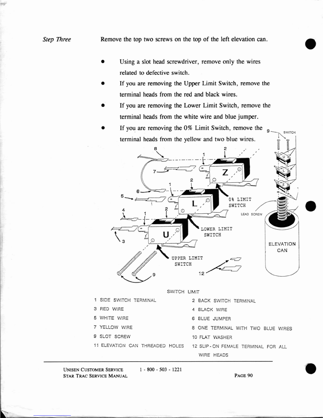
Remove the top two screws on the topofthe left elevation can.
•
•
• Using a slot head screwdriver, remove only the wires
related to defective switch.
•
If
you are removing the Upper Limit Switch, remove the
terminal heads from the red and black wires.
•
If
you are removing the Lower Limit Switch, remove the
terminal heads from the white wire and blue jumper.
If
yo~
are removing the 0% Limit Switch, remove the 9
SWITCH
•
ELEVATION
CAN
LEAD SCREW
LOWER
LIMIT
SWITCH
terminal heads from the yellow and two blue wires.
8 2 "
"-
1 t
..
' "
~7~·~~-~Q3,,~1
5 6 -
-)V~-~-
~~~
--
~
-
0%
LIMIT
SWITCH
4 2
\ 1
~
~-~l-~--~
~-
\3 ,0
\=---::-r.,.-L--.".r-=-
h~
/
~
OPPER LIMIT
~
SWTCH
/~
'9
12
~
1 SIDE SWITCH TERMI AL
3
RED
WIRE
5 WHITE
WIRE
7 YELLOW
WIRE
9 SLOT SCREW
SWITCH LIMIT
2 BACK SWITCH TERMINAL
4 BLACK
WIRE
6 BLUE JUMPER
8 ONE TERMI
AL
WITH
TWO
BLUE
WIRES
10 FLAT WASHER
11
ELEVATION CA THREADED HOLES 12 SLIP -ONFEMALE TERMINAL
FOR
ALL
WIRE HEADS
UN1SEN CUSTOMER SERVICE
STAR
TRAC
SERVICE MANUAL
1 -
800-503-1221
PAGE
90
•
Page 79
•
•
Step Four
Step Five
Step Six
Step Seven
Replace the limit switch by reconnecting the terminal heads and
wires.
•
If
you are replacing the Upper Limit Switch, reconnect
the terminal headsofthe red wire on to the side switch
terminal. Reconnect the terminal headsofthe black wire
on to the back switch terminal.
•
If
you are replacing the Lower Limit Switch, reconnect
the terminal heads
of
the white wire on to the side switch
terminal. Reconnect the terminal headsofthe blue
jumper on to the back switch terminal.
•
If
you are replacing the 0% Limit Switch, reconnect the
terminal head
of
the yellow wire on to the side switch
terminal. Reconnect the terminal heads with the blue
wires jumper
on
to the back switch terminal.
Replace the motor shroud
by
removing the bungie cord and
lowering the motor shroud until it touches the frame. Press the
sidesofthe motor shroud to the frame and attach the velcro
fasteners. Using the Phillips screwdriver, tighten the screw
in
the centerofthe motor shroud.
Plug the treadmill into the power outlet.
Turn the power switch to the ON position.
•
UNISEN CUSTOMER SERVICE
STAR
TRAC
SERVICE
MANUAL
1 -
800-503-1221
PAGE 91
Page 80

RPM SENSOR
REPLACEMENT
You will need the following tools to replace the RPM sensor:
• One 1/8" Allen Wrench
• One
1/8" T-handle Hex Key
• One 5/64" T-handle Hex Key
• One Slot Head Screwdriver
CAUTION
Always turn the power switch to the OFF position. Unplug the treadmill power
cord from the power outlet.
•
•
Step One
Step
Two
Verify the STAR TRAC treadmill is unplugged from the power
outlet.
Raise the motor shroud by using the Phillips screwdriver
to
remove the screwinthe motor shroud. Gently lift the motor
shroud
up
the display handrail. Using the bungie cord from the
ST
AR
TRAC Toolkit, hold the motor shroud at the topofthe
display handrail.
UNISEN CUSTOMER SERVICE
STAR TRAC SERVICE
MANUAL
1 . 800 . 503 •
1221
PAGE
92
•
Page 81
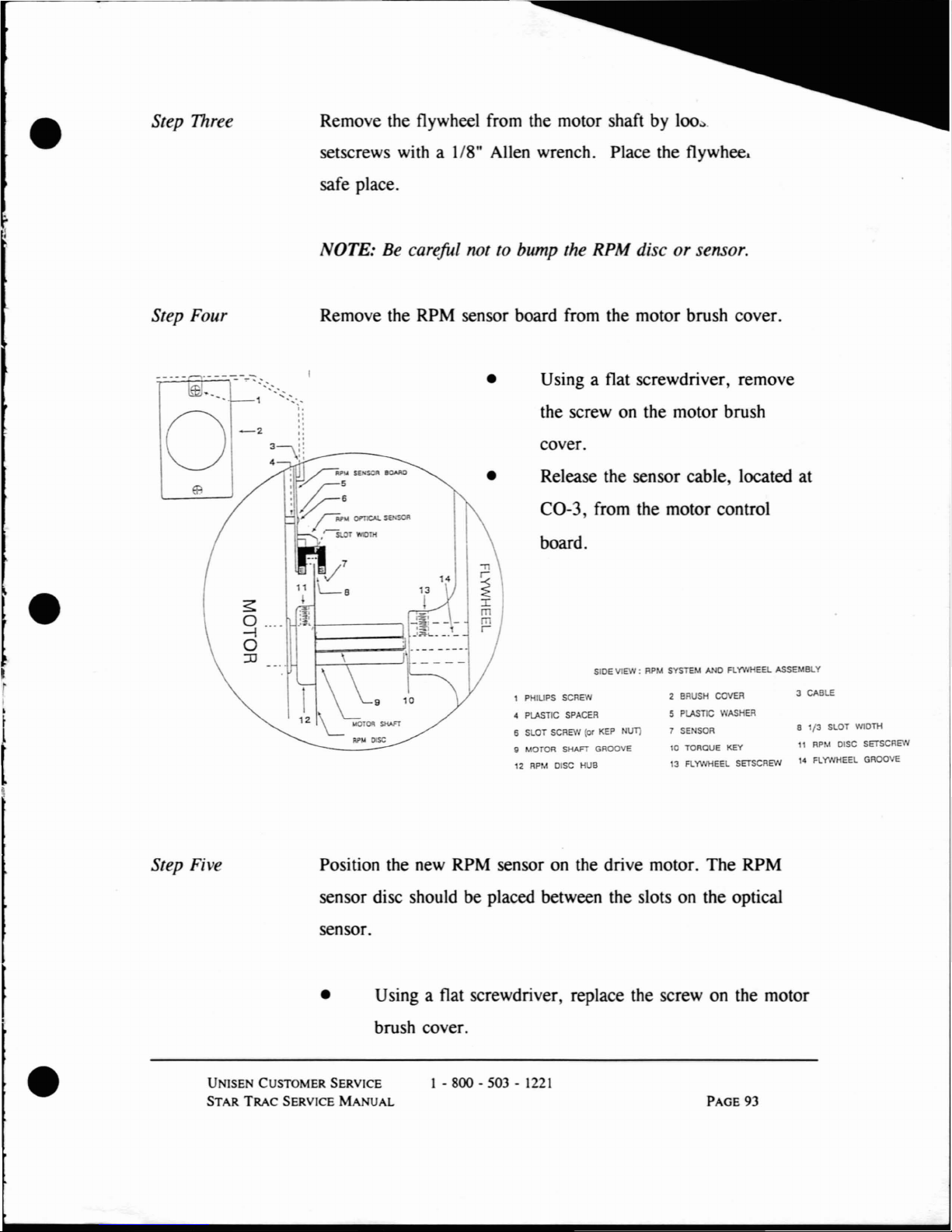
•
Step Three
Remove the flywheel from the motor shaft by
100:>.
setscrews with a 1/8" Allen wrench. Place the flywhee,
safe place.
NOTE: Be
carefuL
not to bump the RPM discorsensor.
Step Four Remove the RPM sensor board from the motor brush cover.
SIDE VIEW:
RPM
SYSTEM
ANDFlYVlHEEL ASSEMBLY
cover.
• Using a flat screwdriver, remove
the screw on the motor brush
a 1{3 SLOT WIDTH
11
RPM
DISC
SETSCREW
l'
FLYWHEEL GROOVE
3
CABLE
10
TORQUE
KEY
13
FLYWHEEL
SETSCREW
2
BRUSH
COVER
5 PLASTIC
WASHER
7
SENSOR
Release the sensor cable, located at
CO-3, from the motor control
board.
12
RPM
DISC
HUB
1 PHIUPS
SCREW
~
PLASTIC
SPACER
6 SLOT
SCREW
(or
KEP
NI1T1
g
MOTOR
SHAFT
GROOVE
•
9
12
L "-0100
SHAFT
Ri'~
DlSC
s
0 ....
-l
o
:0
-2
o
•
I
•
~
Step Five Position the new RPM sensor on the drive motor. The RPM
sensor disc should be placed between the slots on the optical
sensor.
• Using a flat screwdriver, replace the screw on the motor
brush cover.
•
UN1SEN CUSTOMER SERVICE
STAR
TRAC
SERVICE
MANUAL
1 - 800 - 503 -
1221
PAGE
93
Page 82

Step
Six
Step
Seven
Step
Eight
Step
Nine
Replace the flywheel
on
the motor shaft by tightening the two
setscrews with a 1/8" Allen wrench.
NOTE:
Be
careful not to bump the RPM discorsensor.
Replace the motor shroud by removing the bungie cord and
lowering the motor shroud until it touches the frame. Press the
sides
of
the motor shroudtothe frame and attach the velcro
fasteners. Using the Phillips screwdriver, tighten the screw
in
the centerofthe motor shroud.
Plug the treadmill into the power outlet.
Tum the power switch
to
the ON position.
•
•
UNlSEN CUSTOMER SERVICE
STAR
TRAC
SERVICE
MANuAL
1 - 800 - 503 -
1221
PAGE
94
•
Page 83
•
MOTOR
Co TROL BOARD REPLACEMENT
You will need the following tools:
•
•
•
7/16" Socket Wrench
Slot Head Screwdriver
Phillips Screwdriver
CAUTION
Always tum the power switch to the
OFF
position. Unplug the treadmill power
cord from the power outlet.
UNISEN
CUSTOMER
SERVICE
STAR
TRAC
SERVICE
MANUAL
•
l
i
I
I
~
l
l.
Step One
Step
Two
Step Three
Verify the STAR TRAC treadmillisunplugged from the power
outlet.
Raise the motor shroud by using the Phillips screwdriver to
remove the screw
in
the motor shroud. Gently lift the motor
shroud up the display handrail. Using the bungie cord from the
ST
AR
TRAC Toolkit, hold the motor shroud at the topofthe
display handrail.
Wait for
three minutes.
1 - 800 - 503 -
1221
PAGE 95
Page 84

Step Four
Step Five
Step Six
Step Seven
Step Eight
Without crossing the wires, disconnect the red and black wires
on the large blue capacitor, located behind the Motor Control
Board.
Disconnect the elevation motor, limit switches, and auto
transformer connectors from their terminals.
Disconnect the display cable, 0% cable, RPM sensor, and
elevation sensor.
Remove the terminal wires from CO-2 one at a time.
Using the socket wrench, remove the two mounting bolts located
at the bottom
of
the motor control board. Using a Phillips
screwdriver, remove the motor control board.
•
•
UNISEN
CUSTOMER SERVICE
STAR
TRAC
SERVICE MANUAL
1 - 800 - 503 -
1221
PAGE 96
•
Page 85

•
•
Step Nine
Step
Ten
Step Eleven
Step Twelve
Step Thineen
Step Founeen
Step Fifteen
Step Sixteen
Step Seventeen
Position the new motor control board on the frame. Insert the
screws and tighten.
Using a socket wrench, replace the two mounting bolts located
at the bottom
of
the motor control board. Replace the motor
control board screw, using a Phillips screwdriver.
Reconnect the terminal wires from CO-2 one at a time.
Reconnect the display cable, 0% cable, RPM sensor, and
elevation sensor.
Reconnect the elevation motor, limit switches, and auto
transformer connectors to their terminals.
Without crossing the wires, reconnect the red and black wires
on the large blue capacitor, located behind the Motor Control
Board.
Replace the motor shroud by removing the bungie cord and
lowering the motor shroud until it touches the frame. Press the
sides
of
the motor shroud to the frame and attach the velcro
fasteners. Using the Phillips screwdriver, tighten the screw
in
the centerofthe motor shroud.
Plug the treadmill into the power outlet.
Tum
the power switch to the ON position.
•
UNlSEN CUSTOMER SERVICE
STAR
TRAC
SERVICE MANUAL
1 - 800 - 503 -
1221
PAGE
97
Page 86
FLYWHEEL
REPLACEMENT
You will need the following tools:
• 1/8" T-handle Hex
Key
• Rubber Mallet
CAUTION
Always tum the power switchtothe OFF position. Unplug the treadmill power
cord from the power outlet.
e
Step One
Step
Two
Verify the STAR TRAC treadmill is unplugged from the power
outlet.
Raise the motor shroud by using the Phillips screwdriver to
remove the screw
in
the motor shroud. Gently lift the motor
shroud
up
the display handrail. Using the bungie cord from the
STAR TRAC Toolkit, hold the motor shroud at the top
of
the
display handrail.
e.
UNlSEN
CUSTOMER SERVICE
STAR
TRAC
SERVICE
MANUAL
1 - 800 - 503 -
1221
PAGE
98
e
Page 87

•
•
Step Three
Step Four
Step Five
Step Six
With a
118"
T handle hex key, loosen the setscrews on the
flywheel.
• Carefully remove the flywheel by tapping with a rubber
mallet.
Be careful not to loose the torque key.
NOTE:
Be
careful not to touch the RPM optical sensor and
disc.
FLYWHEEL
HEAD ROLLER
Place the torque keyinthe motor shaft. One endofthe torque
key should touch the RPM disc hub.
Align the flywheel groove with the motor shaft groove.
Carefully tap the flywheel on the motor shaft with the rubber
mallet.
• Verify the flywheel
is
on the motor shaft and resting
against the RPM disc.
•
UNISEN CUSTOMER SERVICE
STAR
TRAC
SERVICE
MANUAL
1-
gOO-503-1221
PAGE
99
Page 88

Step Seven
Step Eight
Step Nine
Step
Ten
With a 1/8" T handle hex key, tighten the set screws on the
flywheel.
Replace the motor shroud by removing the bungie cord and
lowering the motor shroud until it touches the frame. Press the
sides
of
the motor shroud to the frame and attach the velcro
fasteners. Using the Phillips screwdriver, tighten the screw
in
the centerofthe motor shroud.
Plug the treadmill into the power outlet.
Tum the power switch to the ON position.
•
•
UNISEN CUSTOMER SERVICE
STAR TRAC SERVICE
MANuAL
1 -
800
- 503 - 1221
PAGE 100
•
Page 89
"T.
•
MOTOR
PuLLEY
REPLACEMENT
You will need the following tools:
• 3/32" T-handle Hex Key
• Phillips Screwdriver
• 12" Ruler
CAUTION
Always tum the power switch to the OFF position. Unplug the treadmill power
cord from the power outlet.
•
Step One
Step
Two
Verify the STAR TRAC treadmill is unplugged from the power
outlet.
Raise the motor shroud by using the Phillips screwdriver to
remove the screw
in
the motor shroud. Gently lift the motor
shroud up the display handrail. Using the bungie cord from the
STAR TRAC Toolkit, hold the motor shroud at the top
of
the
display handrail.
•
UNlSEN
CUSTOMER SERVICE
STAR
TRAC
SERVICE
MANUAL
1 - 800 - 503 -
1221
PAGE
101
Page 90
Step Three
Step Four
Step Five
Step Six
Step Seven
Step Eight
Remove the motor belt from the motor pulley.
• Simultaneously, rotate the flywheel forward, then
backward one revolution, while firmly pushing down and
to the left. Continue until the motor belt slips off.
Loosen the set screws
in
the pulley hub.
• Using a 3/32" T handle hex key, tum the set screws
counter-clockwise. Place the set screws
in
a safe place.
Slide the motor pulley from the motor shaft.
Place the torque key
in
the motor shaft. Slide the motor pulley
over the torque key and motor shaft.
Align the motor pulley with the headroller pulley, using a
12"
ruler. Tighten the setscrews.
Replace the motor belt.
• Simultaneously, rotate the flywheel forward, then
backward one revolution, while firmly pushing down and
right on the motor belt. Continue until the motor belt
slides on.
•
•
UNlSEN CUSTOMER SERVICE
STAR
TRAC
SERVICE
MANUAL
1 -
800-503-1221
PAGE
102
•
Page 91
•
•
Step Nine
Step
Ten
Step Eleven
Replace the motor shroud by removing the bungie cord and
lowering the motor shroud until it touches the frame. Press the
sides
of
the motor shroud to the frame and attach the velcro
fasteners. Using the Phillips screwdriver, tighten the screw
in
the centerofthe motor shroud.
Plug the treadmill into the power outlet.
Tum the power switch to the ON position.
•
UNISEN
CUSTOMER SERVICE
STAR
TRAC
SERVICE
MANUAL
1 - 800 - 503 -
1221
PAGE
103
Page 92
RIGHT
OR
LEFT HANDRAIL REPLACEMENT
NOTE: Treadmills without handrails
may
not have handrails added at a later date.
You will need the following tools:
• 5/32" Hex Key
• 1/4" Hex Key Driver
CAUTION
Always tum the power switchtothe OFF position. Unplug the treadmill power
cord from the power outlet.
•
•
Step One
Step
Two
Verify the STAR TRAC treadmill is unplugged from the power
outlet.
Remove the handrail.
• Using a 1/4" hex key driver, remove the socket head
bolt, lock washer, and flat washer located under the side
foot. Remove the gasket above the side foot. Place the
bolt, washers, and gasket
in
a safe place.
UNISEN CUSTOMER SERVICE
STAR
TRAC
SERVICE
MANUAL
1 - 800 - 503 -
1221
PAGE 104
•
Page 93
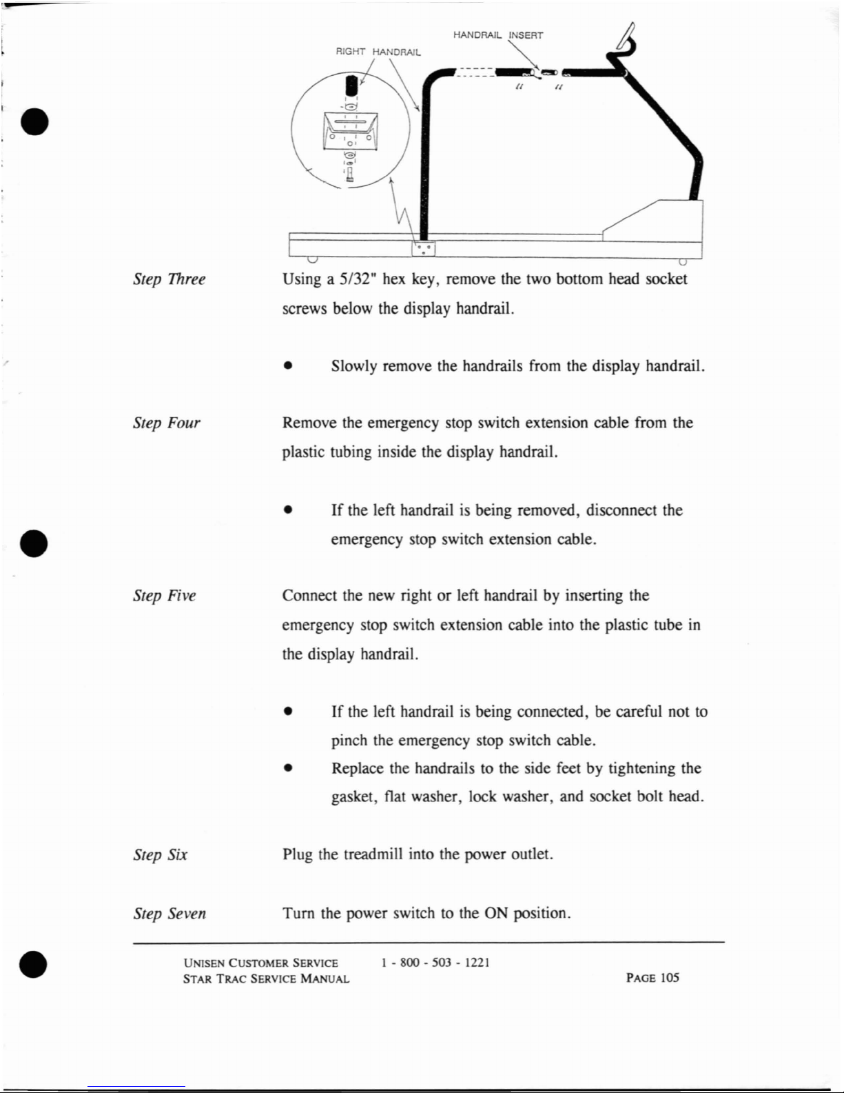
'.
_-_-_-=.-=--=-~e!ID
~_
..
~
II
HANDRAIL INSERT
•
Step Three
Using a 5/32"
hex
key, remove the two bottom head socket
screws below the display handrail.
• Slowly remove the handrails from the display handrail.
Step Four Remove the emergency stop switch extension cable from the
plastic tubing inside the display handrail.
•
•
If
the left handrailisbeing removed, disconnect the
emergency stop switch extension cable.
Step Five
Connect the new rightorleft handrail by inserting the
emergency stop switch extension cable into the plastic tube
in
the display handrail.
•
If
the left handrailisbeing connected, be careful not to
pinch the emergency stop switch cable.
• Replace the handrails
to
the side feet by tightening the
gasket flat washer lock washer, and socket bolt head.
Step Six
Plug the treadmill into the power outlet.
Turn the power switch to the ON position.
•
Step Seven
UNlSE
CUSTOMER SERVICE
STAR
TRAC
SERVICE MANUAL
I - 800 - 503 -
1221
PAGE 105
Page 94
SUK
DECK
REPLACEMENT
The slik deck may need replacingifthe surface feels soft, the deck creaks when
running,
or
the mjddle portion is worn down to the wood. You will need the
following tools:
• Large Phillips screwdriver
• 1/4" and 1/8" Allen wrenchs
CAUTION
Always tum the power switch to the OFF position.
Unp.1ug
the treadmill power
cord from the power outlet.
NOTE:Ifyou have a 2000 Series treadmill with elevation, raise the treadmill to the
highest percent
grade elevation. A 3000 Series treadmill does not need to be elevated.
•
•
Step One
Step
Two
Remove the power plug from the outlet.
Raise the motor shroud by using the Phillips screwdriver to
remove the screw in the motor shroud. Gently lift the motor
shroud
up
the display handrail. Using the bungie cord from the
STAR TRAC
Toolkit, hold the motor shroud at the topofthe
display handrail.
UNISEN
CUSTOMER SERVICE
STAR
TRAC
SERVICE
MANUAL
1 - 800 - 503 -
1221
PAGE
106
•
Page 95
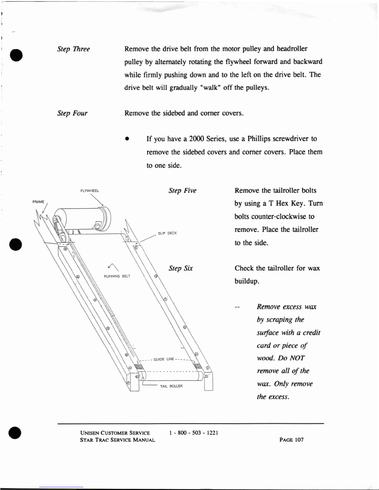
•
Step Three
Remove the drive belt from the motor pulley and headroller
pulley by alternately rotating the flywheel forward and backward
while firmly pushing down and
to
the left on the drive belt. The
drive belt will gradually "walk"
off
the pulleys.
Step Four
Remove the sidebed and comer covers.
•
If
you have a 2000 Series, use a Phillips screwdriver to
remove the sidebed covers and comer covers. Place them
to
one side.
FLYWHEEL
Step
Five
Remove the tailroller bolts
by using a T Hex Key.
Tum
bolts counter-clockwise to
remove. Place the tailroller
sUP
OECK
•
to
the side.
Step Six Check the tailroller for wax
RU
III G
BELT
buildup.
Remove excess wax
by scraping the
surface with a credit
card
or
piece
of
wood. Do NOT
remove all
of
the
TAlL ROlLER
wax. Only remove
the excess.
•
UNISEN CUSTOMER SERVICE
STAR
TRAC
SERVICE
MANuAL
1 -
gOO-503-1221
PAGE
107
Page 96

Step Seven
Step Eight
Step Nine
Remove the headroller bolts by using a T Hex Key.
Tum
bolts
counter-clockwise to remove. Place the headroller to the side.
Raise one side
of
the slik deck approximately two inches and
slide from the treadmill.
If
the opposite sideofthe slik deck coated with wax and
has not been used previously,
tum
the slik deck over and
slide back on
to the treadmill.
If
the both sidesofthe slik deck have been used, remove
from the treadmill and discard.
Position the new slik deck with the wax side up and slide it
between the running belt.
NOTE:
If
you have a 2000 Series, be careful not to damage the
static line running under the treadmill.
• Check the condition
of
the running belt. For additional
information on running belts, please refer to the section
on Running Belt Troubleshooting.
•
•
NOTE:
The
running belt must be replaced,ifit is worn. Placing a good slik deck on
a worn running belt will require additional repairs in the nearfuture.
UNISEN CUSTOMER SERVICE
STAR
TRAC
SERVICE
MANUAL
I - 800 - 503 -
1221
PAGE
108
•
Page 97

•
•
Step Ten
Step Eleven
Step Twelve
Replace the headroller by sliding it through the running belt and
placing it on the brackets. Replace and tighten the headroller
bolts by turning them approximately two turns.
• Tighten the front left and right roller bolts as far as
possible.
• Verify the position
of
the drive belt around the pulley.
If
notinthe correct position, re-position the drive belt.
Replace the tailroller by sliding it through the running belt and
on to the brackets. Replace and tighten the tailroller bolts.
• Turn each tailroller bolt enough to remove the slack from
the running belt.
Verify the alignment and tension
of
the running belt.
•
Pluginthe power outlet. Turn the power switch to the
ON position .
•
PAGE 109
Page 98
•
Check the running belt tension by accelerating the speed
to 2 mph. Stand at the side
of
the treadmill. Grasping the
handrails firmly, place one foot on the treadmill with a
very sharp impact. The running belt should not stop.
If
the running belt does not stop, the running belt
tension is good.
If
the running belt stops, tighten the tai/roller
bolts by turning
for
one revolution. Repeat the
step until the tension
is
correct.
•
• Verify the running belt tracking by accelerating the speed
to 5 mph.
Stand behind the treadmill and visually check for
tracking problems.
NOTE: For additional infonnation on running belts, please refer to
Running
Belt
Replacement.
•
Step Thineen
Replace the motor shroud by removing the bungie cord and
lowering the motor shroud until it touches the frame. Press the
sides
of
the motor shroudtothe frame and attach the velcro
fasteners. Using the Phillips screwdriver, tighten the screw
in
the centerofthe motor shroud.
PAGE 110
•
Page 99

•
RUNNING
BELT
REPLACEMENT
NOTE: For additional information on troubleshooting running belt problems, please
refer to
Chapter
Four:
Troubleshooting.
CAUTION
Always turn the power switch to the
OFF
position. Unplug the treadmill power
cord from the power outlet.
•
Step One
Step
Two
Step Three
Verify the STAR TRAC treadmillisunplugged from the power
outlet.
Raise the motor shroud by using the Phillips screwdriver to
remove the screw in the motor shroud. Gently lift the motor
shroud up the display handrail. Using the bungie cord from the
STAR TRAC Toolkit, hold the motor shroud at the top
of
the
display handrail.
Remove the motor belt from the motor pulley.
•
• At the same time, rotate the flywheel forward and
backward one revolution, while firmly pushing down and
to the left (where it approaches the motor pulley).
• Continue until the motor belt slips
off
the motor pulley
or
headroller pulley.
)
STAR TRAC SERVICE
MANUAL
Page 100

Remove the sidebed and comer covers.
Step Four
•
If
you have a 2000 Series, use a Phillips screwdriver to
remove the sidebed covers and comer covers. Place them
to
one side.
•
Step Five
Step Six
Step Seven
Step Eight
Remove the tailroller bolts by using a T Hex Key.
Tum
bolts
counter-clockwise
to
remove. Place the tailrollertothe side.
Remove the headroller bolts
by
using a T Hex Key.
Tum
bolts
counter-clockwise to remove. Place the headroller
to
the side.
Raise one side
of
the slik deck approximately two inches and
slide from the treadmill.
Remove running belt.
PAGE 112
•
 Loading...