

Start italiana XMT-SI-485, XMT-SI-RF Installation Manual
INSTALLATION
MANUAL
XMT
-
SI
-
485
XMT
-
SI
-
RF
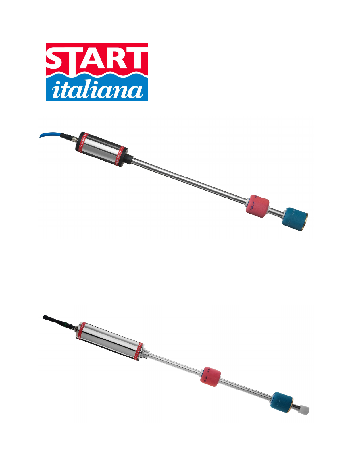
MAGNETOSTRICTIVE
I.S. PROBE
WIRELESS
I.S. PROBE

XMT-SI-485 – XMT-RF eng rev04 12/2013
2

XMT-SI-485 – XMT-RF eng rev04 12/2013
3
INDEX:
INTRODUCTION...…...….………………………………………………………………………………………...… pag. 4
GENERAL WARNINGS……...……………………………………………………………………………………… pag. 4
GENERAL INFORMATION…...……………………………………...……………………………………………... pag. 5
TECHNICAL CHARACTERISTICS XMT-SI………………………………………………………………………. pag. 6
PRODUCT LABEL..………...……………………………………………………………………………………...... pag. 8
MECHANICAL INSTALLATION XMT-SI…………………………………………………………………………... pag. 9
EXAMPLE OF RISER PREPARATION FOR RF PROBES……...……………………………………………… pag.11
ELECTRICAL CONNECTION……………………………...……………………………………………………….. pag.14
JUMPER SETTING………………………..………….……………………………………………………………… pag.15
XMT-SI-RF MODEL…………….……..……………………………………………………………………………... pag.16
XMT-SI-485 MODEL…………………………………………………………………………………………………. pag.18
XMT-SI-485-LOG – PROBE WITH MEMORY AND DATA LOGGER FUNCTIONALITY…………………… pag.20
XMT-SI-485 – XMT-RF eng rev04 12/2013
4
INTRODUCTION
This manual gives all the installation and use instructions for XMT-SI level probes family .
GENERAL WARNINGS
• Before the installation and use of the equipment please carefully read the instructions given into this manual.
• The manufacturer is not responsible of any possible operation not mentioned into this manual.
• Any failure or faulty operation would occur to the equipment, please refer to the authorized personnel for
maintenance or directly to the manufacturer.
• The manufacturer refuses all responsibility for any eventual injury and/or damage to things caused to the non-
observance of the safety regulations.
• The assigned personnel is required to know all the safety regulations relative to the hereby described
equipment.
• Any doubt may occur about the functioning of the equipment please refer to the authorized personnel for
maintenance or directly to the manufacturer.
• Tampering releases the manufacturer from any responsibility in front of the competent authority.
• This product is used in fuel tanks and in hazardous areas for risk of explosion and fire.
Subterranean leakages of the fuel tanks may cause serious damages to environment and injury.
• If mixed with air, the flammable vapors may cause explosion. Hazardous areas may be originated
therefore by the presence of gas or vapors.
• Explosions or fire may cause damages, even lethal.
• The magnetostrictive probe can be installed in hazardous areas.

XMT-SI-485 – XMT-RF eng rev04 12/2013
5
GENERAL INFORMATION
The magnetostrictive level transmitters are based on the principle named Wiedemann effect and enable continuous
and highly accurate reading of liquid’s level.
The XMT-SI level transmitter consists of a microprocessor based electronic circuit placed inside one aluminium
case head and a stainless steel shaft containing a wave guide placed inside the tank.
An high frequence electric impulse is transmitted through the electronic device. In the matching point with the
magnetic field generated by the permanent magnet placed inside the float, a mechanic impulse is generated thanks
to the magnetostrictive torsional strain. The mechanic impulse spreads through the wave guide to the speed of
sound up to the sensor placed in the measuring head. The timing between the transmission of the going impulse
and the return impulse exactly defines the position of the floats.
XMT-SI family are high precision measure instrumentation which are suitable to measure product level, water level
and temperature in various type of underground and above ground tank, also placed in hazardous areas.
The XMT-SI family is intrinsically safe certified for 0 Zone and through an intrinsically safety barrier can be
connected to console or PC positioned in a safety zone for having a complete control of the tank.
The following models are available:
XMT-SI-485 transmits data on the 485 bus. It can be configured for polling mode or push mode functioning based
on the needing. It is externally powered by the communication bus.
XMT-SI-RF transmits data using a radiofrequency transmission with variable frequency depending on the level
changes inside the tank. It is powered by a lithium battery positioned inside the probe and certified also for
intrinsically safety. In order to grant the intrinsically safety of the transmitter, the battery must be replaced only by
another one supplied by Start Italiana.
XMT-SI-TTL transmits data using a TTL interface for OEM applications. The associated instrument must be
certified in case it is necessary to install the product in a certified zone.
XMT-SI-485-LOG transmits data on a 485 bus. It is configured for functioning in polling mode. Normally it is
powered externally using a communication bus. If the external power is disconnected, automatically a battery
placed inside allows to keep the probe working and stores the level changes in a non-volatile memory for
subsequent download of the data possible on recovery of the main supply.

XMT-SI-485 – XMT-RF eng rev04 12/2013
6
TECHNICAL CHARACTERISTICS XMT-SI
Four types of interface are available:
RS 485 serial door for multipoint connection
• Power supply 12 VDC through an intrinsically safe barrier.
• Consumption <15 mA @ 12 Vdc normal functioning
• Consumption < 200 uA @12 Vdc in sleep mode functioning
• Connection cable: hydrocarbons resistant, suitable for underground pose with insulation 0,6-1KV, 2
shielded and twisted pairs, section of the power cable pair of at least 1mm2.
• Type of cable supplied by Start Italiana: LiYstCYY INSULATION LEVEL 4 (0,6/1KV) - (2x0.25mm²) +
2x1.00mm² CEI 20-22II IEC 60332-3A ENI 00.181.00
• Maximum transmission distance: up to 2 Km based on standard of RS485 interface.
RF interface:
• Internal power supply through an instrinsically safe battery 3.6V, 16Ah
• Low frequency transmission to a receiver located in a safety zone.
• Consumption <15 mA @ 12 Vdc normal functioning
• Consumption < 200 uA @12 Vdc in sleep mode functioning
TTL Interface for OEM applications:
• Power supply 5Vmax, 100mA max from certified external device
• Serial transmission TTL levels
• Maximum distance:3 mt, compatible with TTL signals
RS485-LOG serial door for multipoint connection with internal battery for storage of data in case of
missing external power supply or polling
• Power supply 12 VDC through an intrinsically safe barrier.
• Consumption <15 mA @ 12 Vdc normal functioning
• Consumption < 200 uA @12 Vdc in sleep mode functioning
• Internal power supply through an instrinsically safe battery 3.6V, 16Ah
• Connection cable: hydrocarbons resistant, suitable for underground pose with insulation 0,6-1KV, 2
shielded and twisted pairs, section of the power cable pair of at least 1mm2.
• Type of cable supplied by Start Italiana: LiYstCYY INSULATION LEVEL 4 (0,6/1KV) - (2x0.25mm²) +
2x1.00mm² CEI 20-22II IEC 60332-3A ENI 00.181.00
• Maximum transmission distance: up to 2 Km based on standard of RS485 interface.
For all the types the measurement characteristics are:
• Electronics based on a Microprocessor
• Support telediagnostics and telemaintenance
• Possibility to configure remotely the functional parameters
• In case of maintenance the internal part of the sensor (wave guide) can be removed without degas the
tank, especially useful for LPG applications where the tanks are in pressure.
• Tank connection:
- Not needed if probe is inserted into a riser with internal diameter 2”
- 2” sliding connection as standard.
- Other type of optional connections under request (nippled fixed, flanged, …)
• Stainless steel case, IP68.
• Probe shaft Stainless Steel AISI 304 / 316

XMT-SI-485 – XMT-RF eng rev04 12/2013
7
• Measurement range: from 200 mm. to 12.500 mm.
• Maximum mechanical length: 13.000 mm.
• Data transmitted:
- Product level in 0.01 mm
- Water level in 0.01 mm
- Medium temperature detected through digital temperature sensor placed along the probe shaft
(max 5)
• Measurement accuracy: +/- 0,5 mm.
• Measurement resolution: +/- 0,05 mm.
• Temperature accuracy: +/- 0,2°C
- Certifications:
- CEC 09 ATEX 131 rev2 : II 1G Ex ia IIB T4 II 1D Ex tD A20 T135°C
- CEC 09 ATEX 131 rev3 : II 1G Ex ia IIB T4 Ga II 1D Ex t IIIC T135°C Da IP66/68
• Approvals :
- OIML-R85 for fixed applications
- OIML-R80 per mobile applications
WIRING OF THE CONNECTOR
XMT-SI-485 – XMT-RF eng rev04 12/2013
8
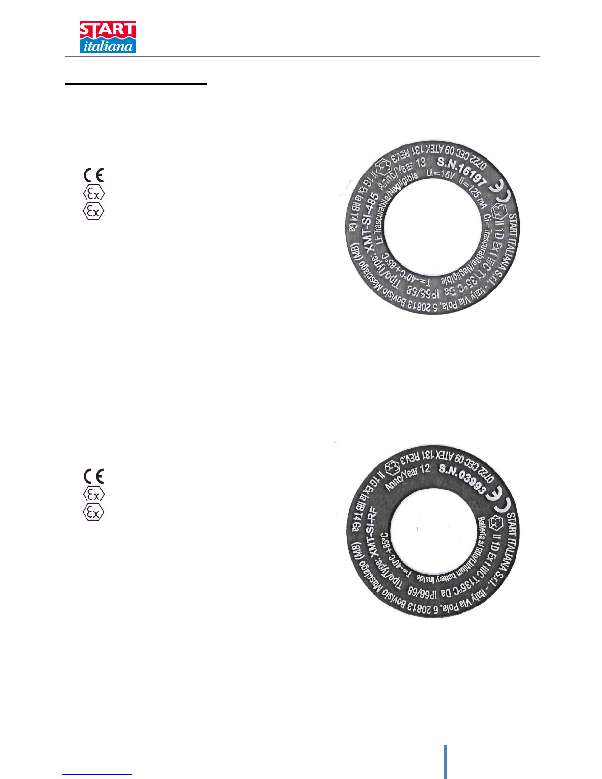
PRODUCT LABEL
XMT-SI-485
START ITALIANA S.r.l. - Italy
Via Pola 6, 20813 Bovisio Masciago (MI)
0722 CEC 09 ATEX 131 REV.3
II 1G Ex ia IIB T4 Ga
II 1D Ex t IIIC T135°C Da IP66/68
Tipo/Type: XMT-SI-485
Anno/Year: 13
S.N.: 12345
T= - 40°C + 85°C
Ui = 16V Ii = 125mA
Ci = trascurabile/negligible
Li = trascurabile/negligible
The serial number is unique and corresponds to the probe address for the consequent configuration into the control
electronics.
XMT-SI-RF
START ITALIANA S.r.l. - Italy
Via Pola 6, 20813 Bovisio Masciago (MI)
0722 CEC 09 ATEX 131 REV.3
II 1G Ex ia IIB T4 Ga
II 1D Ex t IIIC T135°C Da IP66/68
Tipo/Type: XMT-SI-RF
Anno/Year: 12
S.N.: 12345
T= - 40°C + 85°C
Batteria al litio/Lithium battery inside
The serial number is unique and corresponds to the probe address for the consequent configuration into the control
electronics.
 Loading...