

Page 1
USER’S MANUAL
USB 2.0 6in1 / 7in1
Docking Station
DS.2.0.08042003
Page 2
Index
Page
Introduction………………………………………………………………… 1
Features……………………………………………………………………. 1
Specification………………………...………………….………………….. 1
Requirements……………………..….…………………………………… 2
Package contents…………………..……………….……………………. 2
Chapter 1
Hardware Installation Guide…….…..….…………………………………… 3
Used for I/O applications.…..….……………………………………………. 4
Hardware Installation.………………………………………………………. 4
Chapter 2
Software Installation…...…………….……………….…………………….. 5
Host Link on Other Computer……………….………………………………. 26
Running the PC-Linq Program…….………………………………………… 27
NOTICE………………………………………………………….…………
28
Serial/Parallel Port Limitation………………………………………………...
28
Appendix
Software Update……………………………………………………………. 29
USB Speed…………………………….…………..………………………. 29
Abbreviations……………………………………………………………….. 30
Keyed Connector Protocol…………………………..……………………… 31
Macintosh OS Compatibility Testing Report………………..………………… 32
This Product is achieve the USB 2.0 High-Speed, must be plugged in to USB 2.0 Host Port. If
this product is plugged into the USB 1.1 Host port, this product will only have USB 1.1 Full-Speed.
Docking Station Limitation for support
Serial “Keyboard” and “Mouse”
(Page28)
Page 3

- Page 1 -
Introduction:
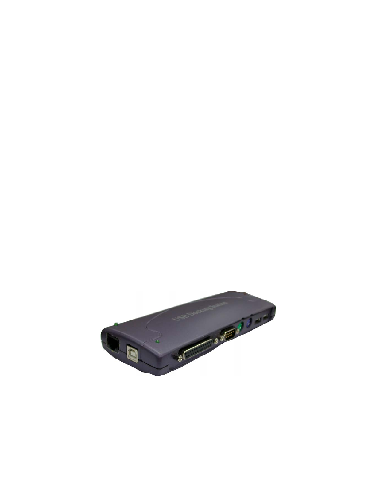
The USB 2.0 Docking Station is an all-in-one hub that could simplify your
computer connections with just one single box. It expands your computer with
one USB Upstream Port, two USB Downstream Ports, one DB25P(female) IEEE
1284 Parallel Port, one DB9P(male) RS232C Serial Port, two PS/2 ports Mini-Din
6P(female), Host Link and one 10/100 Mbps Ethernet RJ-45 Port (7in1). This
exclusive product makes expansion amazingly simple, convenient and the most
important is that it's economical and inexpensive. No complex installation,
confusing cables plug-ins or IRQ’s to worry about. You can simply plug and play
all of your peripherals without re-booting PC computer.
Features:
Support USB 2.0.
USB and ACPI compliant.
Support USB High-Speed 480Mb/Sec or Full-Speed at 12Mb/sec.
USB
Truly Plug & Play automatic system configuration.
Compatible with Notebook & Desktop PCs
Two USB 2.0 Downstream ports.
One PS/2 Port for Keyboard
One PS/2 Port for Mouse
One serial Port.
One Parallel Port (Standard IEEE-1284 Parallel Port)
One USB 1.1 Host Link.
Functions
One USB 2.0 10/100 Ethernet LAN Port (7in1)
OS
Windows 2000, Windows XP, Windows ME, Windows 98SE
Power
The Docking Station use USB Bus and self power
Specification:
Interface
Universal Serial Bus (USB) Revision 2.0 device.
One Upstream Port, USB B-type.
Two USB 2.0 Downstream ports, USB A-type.
One PS/2 Port for Keyboard, 6-pins Mini-Din (female) connector.
One PS/2 Port for Mouse, 6-pins Mini-Din (female) connector.
One serial Port, DB 9-pins (male) connector.
One Parallel Port (Standard IEEE-1284 Parallel Port). DB 25-pins
(female) connector.
One USB 1.1 B-type Host Link.
One USB 2.0 10/100 Ethernet LAN Port, RJ-45 connector. (7in1)
Hubs and devices up to total 127 devices.
Function/
Connector
Plug-and-Play all of your peripherals without re-booting PC computer.
Page 4
- Page 2 -
Expansion amazingly simple.
Cable
USB cable (A to B male)
USB transfer rate: High-Speed 480Mb/Sec.
Transfer
Rate
Data read/write speed: Up to 480Mb/Sec.
Power LED
Host Link LED
LED
Ethernet LED (7in1)
Power
Power Adapter DC 6 V. 2.1A
Enclosure
Plastics.
EMI
CE & FCC.
Requirements:
IBM PC/AT Compatible.
USB 2.0 Host card or USB 2.0 HUB device.
Windows 2000, Windows XP, Windows ME or Windows 98SE operating system.
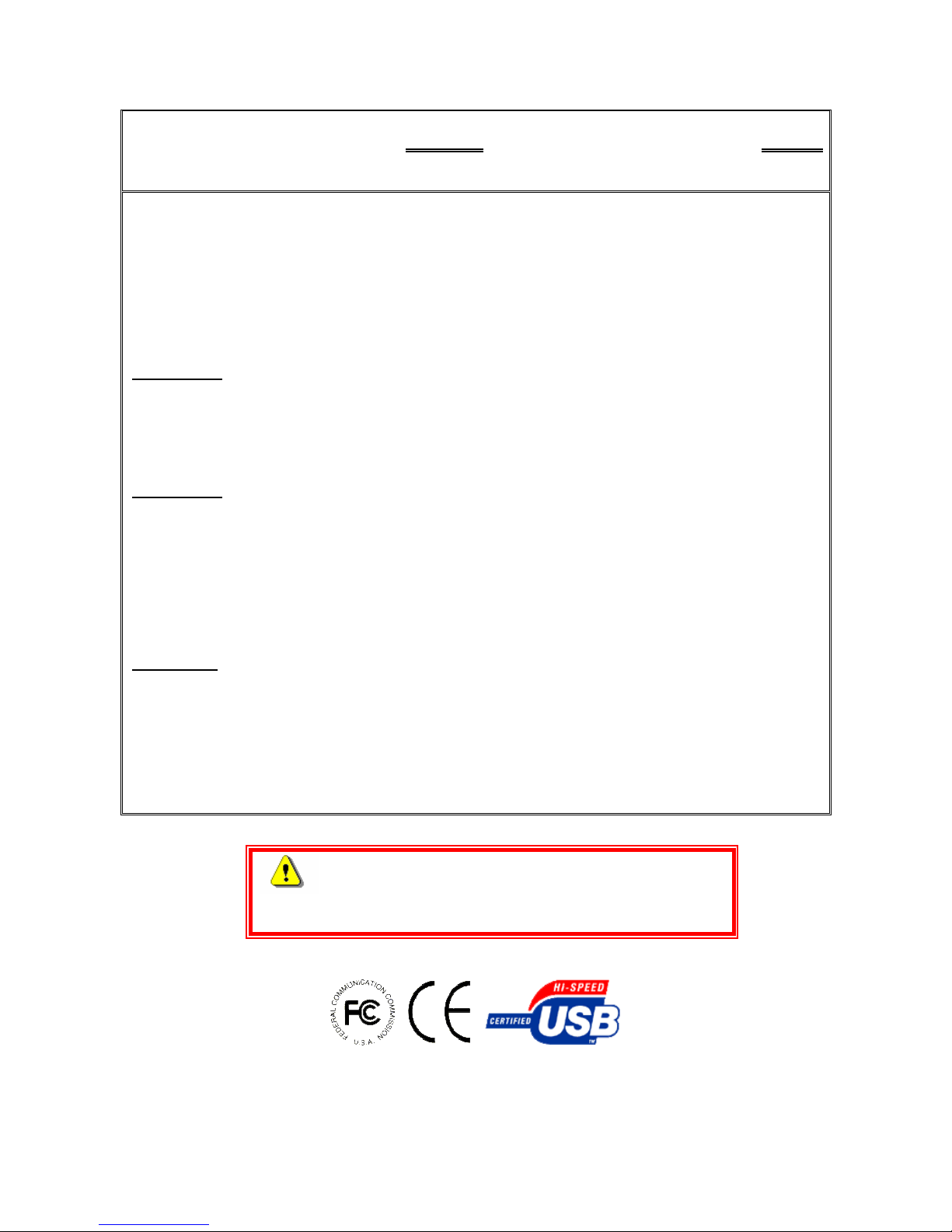
Packing contents:
Please make sure that this package includes the following items.
USB Docking Station – One Software CD Driver include User’s Manual – One
USB cable (A to B male) – One Power Adapter – One
Warnings
Some Main board may have its OWN driver for the USB 2.0 Host driver,
please make sure your Main board or PC manufacturer for update details.
Page 5
- Page 3 -
Chapter 1
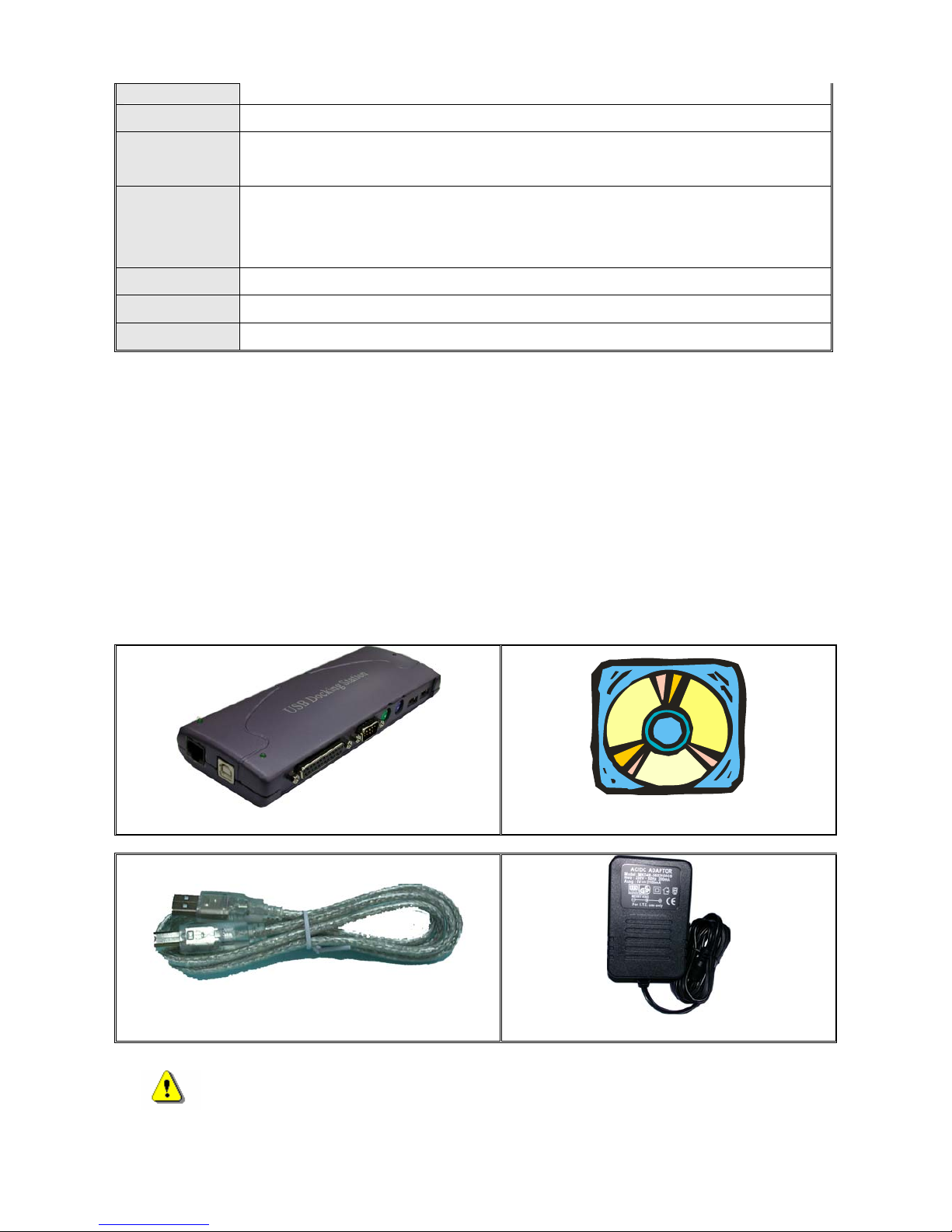
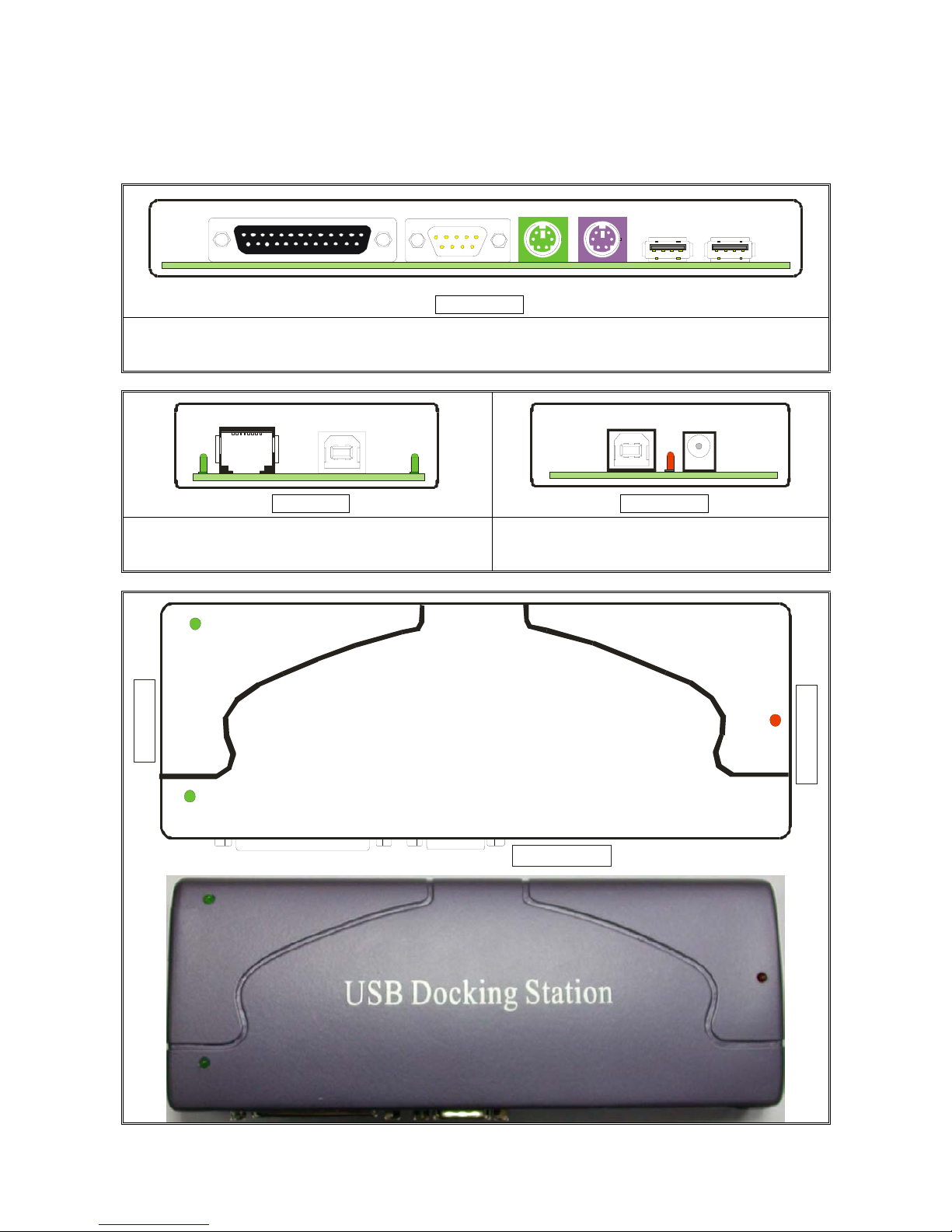
Hardware Installation Guide:
1
2
34
5
6
Front Side
1. Parallel Port (DB25P)
2. Serial Port (DB9P)
3. PS/2 Mouse (Mini-Din 6P)
4. PS/2 Keyboard (Mini-Din 6P)
5. USB 1 (A-type)
6. USB 1 (A-type)
7
8
11
12
9
10
13
Left Side Right Side
7. USB 2.0 Ethernet (RJ-45) (7in1)
8. USB 1.1 Host Link (B-type)
9. Upstream Port (B-type)
10. Power Adaptor
11
12
13
Left Side
Right Side
Front Side
Page 6
- Page 4 -
LED
11. Power LED
12. Ethernet LED (7in1)
13. Host Link LED
Used for I/O applications
USB Port
Digital Camera, Card Reader, Mouse, Scanner, Printer, Removable Storage
Drive
PS/2 Port
Mouse, Keyboard
Serial Port
Modem (Page 28)
Parallel Port
Printer (Page 28)
Host Link
Host Link provides a software tool to enable end-user being capable of
accessing remote file data in remote computer's storage devices through a
simple drag & drop procedure
Ethernet
Pbx, Networking, Dumb Terminal, Point-of-sale
Hardware Installation
Step1:Connect the power jack of the power adapter and plug it into the right side of the
USB Docking Station.
Step2:Find an unused electrical outlet and plug in the power adapter.
Step3:Plug the USB cable “A” type in to free USB Host port on computer.
Step4:Plug the USB cable “B” type into the USB Upstream port connector on the right side
of the USB Docking Station.
Warnings
If your OS is Windows 98SE/ME, Windows has finished installing the software.
Popup “To finish setting up your new hardware, you must restart your computer”
wizard, please choose click “NO” to continue install the driver.
Chapter 2
Software Installation:
Supported OS
Microsoft Windows 2000,Windows XP,Windows ME,Windows 98SE are supported.
Windows will automatically find the USB Docking Station 6in1 / 7in1, will prompt new
hardware wizard. USB 2.0 Ports, PS/2 Keyboard and Mouse Ports, Data Link Port, Serial
Port, Parallel Port and LAN Port (7in1). Please follow the software installation wizard
step-by-step.
Page 7
- Page 5 -
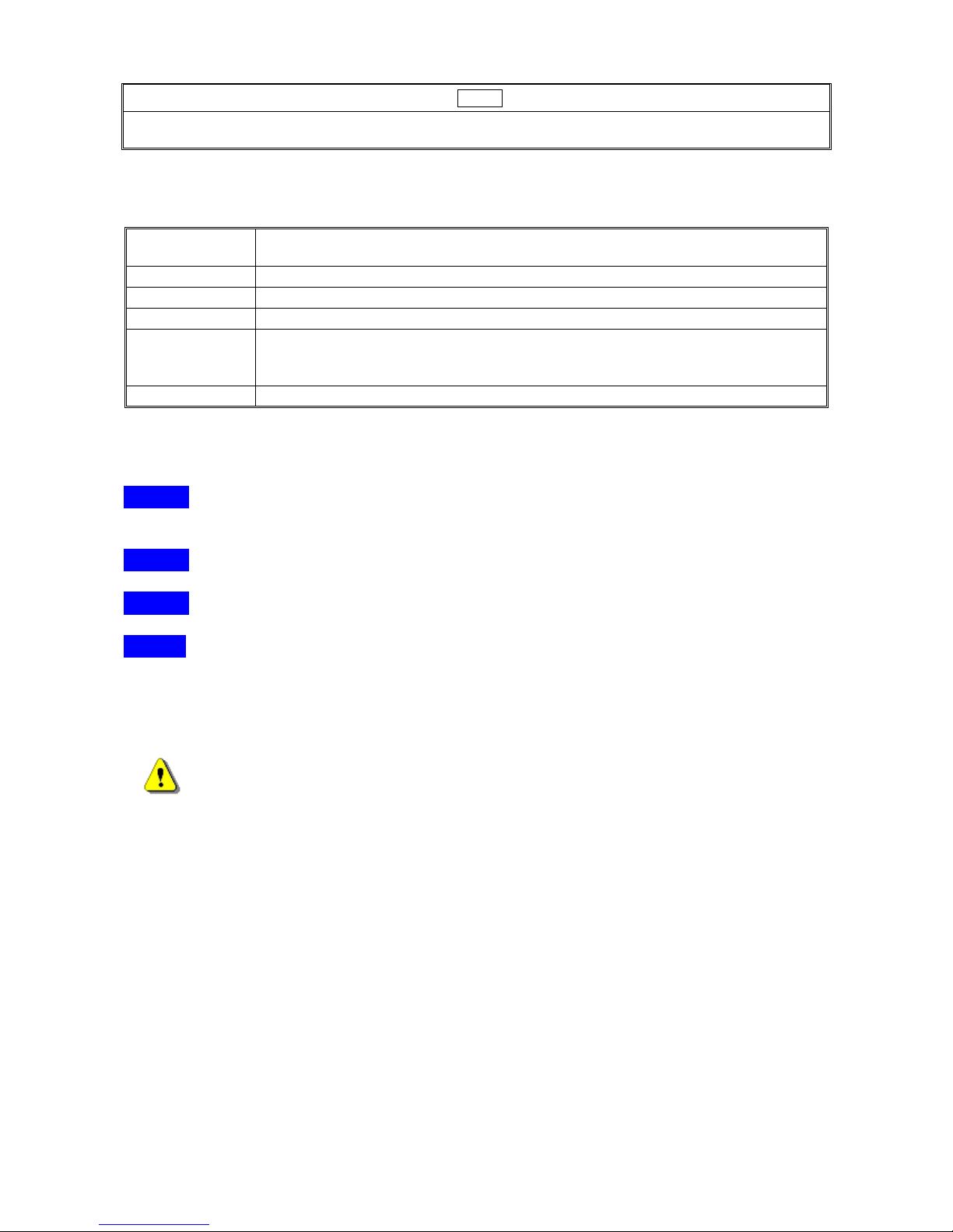
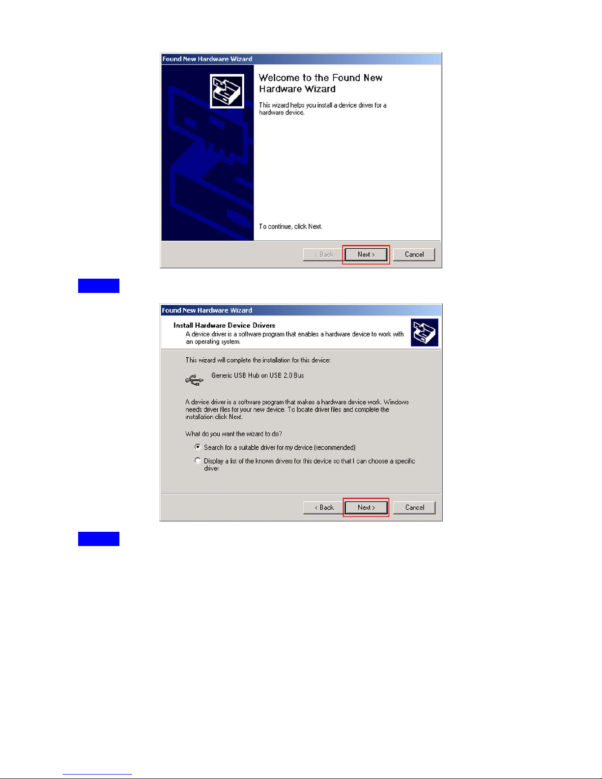
Step1:Found new hardware wizard, insert the Installation CD into CD-ROM, choose click
“Next”.
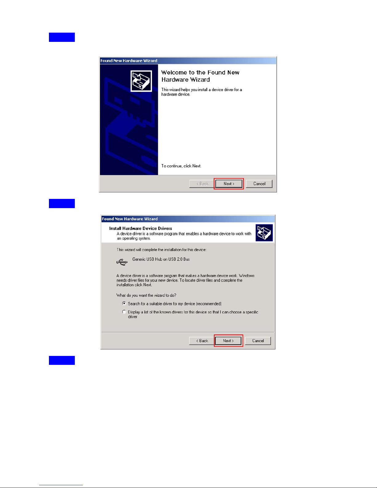
Step2:Choose click “Next”, follow the software installation step-by-step.
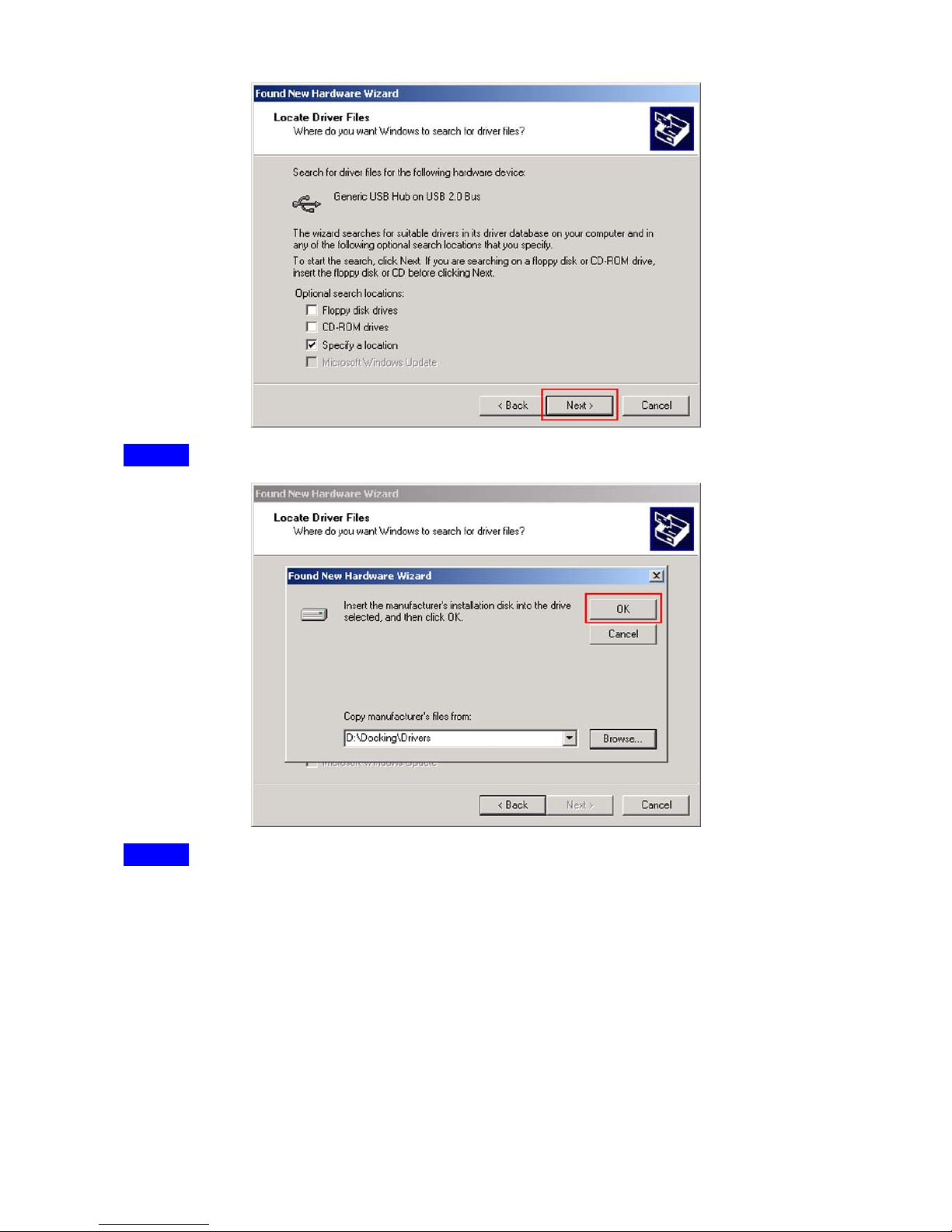
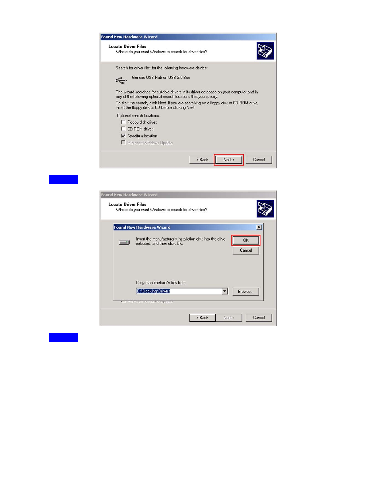
Step3:Select “CD-ROM drives” or “Specify a Location”, choose click “Next”.
Page 8
- Page 6 -
Step4:Browser a CD driver specify a location, choose click “OK”.
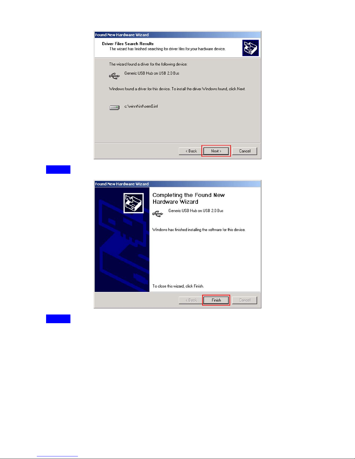
Step5:Choose click “Next”.
Page 9
- Page 7 -
Step6:Choose click “Finish”.
Step7:Choose click “Next”.
Page 10
- Page 8 -
Step8:Choose click “Next”.
Step9:Select “CD-ROM drives” or “Specify a Location”, choose click “Next”.
Page 11
- Page 9 -
Step10:Browser a CD driver specify a location, choose click “OK”.
Step11:Choose click “Next”.
Page 12

- Page 10 -
Step12:Choose click “Finish”.
Step13:Choose click “Next”.
Page 13

- Page 11 -
Step14:Choose click “Next”.
Step15:Select “CD-ROM drives” or “Specify a Location”, choose click “Next”.
Page 14

- Page 12 -
Step16:Browser a CD driver specify a location, choose click “OK”.
Step17:Choose click “Next”.
Page 15

- Page 13 -
Step18:Choose click “Finish”.
Step19:Choose click “Next”.
Page 16

- Page 14 -
Step20:Choose click “Next”.
Step21:Choose click “Next”.
Page 17

- Page 15 -
The PC-Ling icon will appear on the desktop
Step22:Choose click “Next”.
Step23:Choose click “Next”.
Page 18

- Page 16 -
Step24:Select “CD-ROM drives” or “Specify a Location”, choose click “Next”.
Step25:Browser a CD driver specify a location, choose click “OK”.
Page 19

- Page 17 -
Step26:Choose click “Next”.
Step27:Browser a CD driver specify a location, choose click “OK”.
Page 20

- Page 18 -
Step28:Choose click “Finish”.
Step29:Choose click “Next”.
Page 21

- Page 19 -
Step30:Choose click “Next”.
Step31:Select “CD-ROM drives” or “Specify a Location”, choose click “Next”.
Page 22

- Page 20 -
Step32:Browser a CD driver specify a location, choose click “OK”.
Step33:Choose click “Next”.
Page 23

- Page 21 -
Step34:Choose click “Finish”.
Step35:Choose click “Next”.
Page 24

- Page 22 -
Step36:Choose click “Next”.
Step37:Select “CD-ROM drives” or “Specify a Location”, choose click “Next”.
Page 25

- Page 23 -
Step38:Browser a CD driver specify a location, choose click “OK”.
Step39:Choose click “Next”.
Page 26

- Page 24 -
Step40:Choose click “Yes”.
Step41:Choose click “Finish”.
Page 27

- Page 25 -
Step42:The driver has been setup successfully. Please re-start the computer.
Step43:Installation verification.
Page 28

- Page 26 -
Host Link on Other Computer
Step1: Power on both computers where you will connect the PC-Linq cable and make
sure that the USB port is enabled and working properly.
Step2: Plug in the USB cable into the USB port and Windows will detect an unknown
device and run the Add New Hardware Wizard to assist you in setting up the
new device.
Step3: Insert the PC-Linq USB cable driver diskette into the floppy drive and click Next to
continue.
Step4: Select Search for the best driver for your device and click Next.
Step5: Select Floppy disk drives and click OK.
Step6: Windows will detect the driver and shows the USB Bridge Cable. Click NEXT to
continue installation.
Step7: Then the PC-Linq Setup program will start to begin program installation.
Step8: Follow the instructions on every dialog box to finish the installation.
Step9: After installation is complete, a shortcut of the PC-Linq program will be placed on
your Windows desktop.
Page 29

- Page 27 -
Running the PC-Linq Program
Follow the steps below on how to run the PC-Linq program:
Step1: Plug in both ends of the PC-Linq USB cable to the two computers.
Step2: Double-click on the PC-Linq shortcut icon on your desktop screen. Do the same for
the other computer.
Step3: The PC-Linq File Manager will appear on your screen and will detect both the local
and remote machine. This is much similar with Windows Explorer file manager
where you can cut, copy, paste, or drag files and folders.
Step4: You can also print text or document files from the remote machine to your local
printer by clicking on the file and run File-Print command.
Step5: There are two LED-like indicators found on the bottom-right corner of the PC-Linq
File Manager. These indicators show the connection status of the remote and
local machine. The left LED is for the local machine, while the right LED is for the
remote machine. A green LED indicates that the connection is good while a red
LED indicates that connection is not found. Both LEDs need to be in green color
for a proper link and operation. If one LED is red, either the USB cable is not
properly connected, or the software is not properly installed, or the PC is in
suspend mode.
Step6: Click on the Help Topics icon (rightmost icon) for more information on how to use
the program.
Page 30

- Page 28 -
Notice
1. In order to achieve the USB 2.0 Speed for this Docking Station must be plugged in to
USB 2.0 Host and Windows 2000 or Windows XP. If this Docking Station is plugged
into USB 1.1 Host, will only have USB 1.1 Speed.
2. Some Mainboard may have its OWN driver for the USB 2.0 Host drive, please make
sure your Mainboard or PC manufacturer for update details.
3. In windows 98SE and ME, the Docking Station driver has two parts to working with
system, one is virtual COM port driver, and the other one is USB support driver.
Since we designed Docking Station has not IRQ feature to avoid resource consume
(because IRQ is limited), and it want to follow USB spec that can hot plug/unplug, so
Docking Station of driver and hardware both can’t support device that is to operate with
IRQ feature, as we know, the older serial Keyboard and mouse are work with IRQ to
interrupt OS to service its requirement, that’s why Docking Station can’t work in
Keyboard/Mouse.
Serial/Parallel Port Limitation for support serial Keyboard and Mouse
In Windows 98SE and ME, the Serial Port driver has two parts to working with system, one
is virtual COM port driver, and the other one is USB support driver.
Since we designed Serial/Parallel Port has not IRQ feature to avoid resource
consume (because IRQ is limited), and it want to follow USB spec that can hot
plug/unplug, so Serial/Parallel Port of driver and hardware both can’t support
device that is to operate with IRQ feature, as we know, the older serial Keyboard
and mouse are work with IRQ to interrupt OS to service its requirement, that’s
why Serial/Parallel Port can’t work in Keyboard/Mouse.
In Windows 2000/XP, Serial/Parallel Port driver is designed by Microsoft’s
WD M, a nd onl y h av e one d riv er tha t regi str y o n po rt cla ss, in thi s W DM d ri ve r, t he
COM port driver is more close with HID interface, so, Serial/Parallel Port driver
also have some feature near with HID, but because they are different class, so it
must has different in something.
We don’t know how mouse be made by a company, so we don’t know why some
mouse can run well but another couldn’t, we think it relatives with HID and COM.
In fact, we think that only has very, very few people use tradition serial
keyboard/mouse on PC, so the detail reason that why Serial/Parallel Port has
issue with those device, because we haven’t not so many resource to analysis it,
so we let is a limitation on Serial/Parallel Port.
Page 31

- Page 29 -
Appendix
Software Update:
If you have questions about USB 2.0 Host controller and Docking Station, please
refer to this chart for clarifications:
USB 2.0 Host Windows OS USB 2.0 HOST driver update
Windows 98SE
Windows ME
Windows 2000
NEC USB 2.0 Host
Windows XP
OWC(as known as OMI) driver version 2.0.4 or above
Windows 98SE OWC(as known as OMI) driver version 2.0.4 or above
Windows ME OWC(as known as OMI) driver version 2.0.4 or above
Windows 2000 USB 2.0 Host driver
Intel ICH4 Host on
Mainboard
Controller
Windows XP
1. USB 2.0 Host driver
2. Windows XP Service Pack 1
Windows 98SE OWC(as known as OMI) driver version 2.0.4 or above
Windows ME OWC(as known as OMI) driver version 2.0.4 or above
Windows 2000 USB 2.0 Host driver
VIA Host and on
Mainboard
Controller
Windows XP
1. USB 2.0 Host driver
2. Windows XP Service Pack 1
Windows 98SE Not Supported
Windows ME Not Supported
Windows 2000 USB 2.0 Host driver
SiS 962 Host on
Mainboard
Controller
Windows XP
1. USB 2.0 Host driver
2. Windows XP Service Pack 1
USB Speed:
PERFORMANCE APPLICATIONS ATTRIBUTES
LOW-SPEED
• Interactive Devices
• 10 – 100 kb/s
Keyboard, Mouse
Stylus
Game Peripherals
Virtual Reality Peripherals
Lowest Cost
Ease-of-Use
Dynamic Attach-Detach
Multiple Peripherals
FULL-SPEED
• Phone, Audio, Compressed
Video
• 500 kb/s – 10 Mb/s
POTS
Broadband
Audio
Microphone
Lower Cost
Ease-of-Use
Dynamic Attach-Detach
Multiple Peripherals
Guaranteed Bandwidth
Guaranteed Latency
HIGH-SPEED
• Video, Storage
• 25 – 400 Mb/s
Video
Storage
Imaging
Broadband
Low Cost
Ease-of-Use
Dynamic Attach-Detach
Multiple Peripherals
Guaranteed Bandwidth
Guaranteed Latency
High Bandwidth
The USB transfers signal and power over a four-wire cable. The signaling
occurs over two wires on each point-to-point segment.
There are three data rates:
Page 32

- Page 30 -
The USB high• -speed signaling bit rate is 480 Mb/s.
The USB full• -speed signaling bit rate is 12 Mb/s.
A limited capability low• -speed signaling mode is also defined at 1.5 Mb/s.
USB 2.0 host controllers and hubs provide capabilities so that full-speed and
low-speed data can be transmitted at high-speed between the host controller and the hub,
but transmitted between the hub and the device at full-speed or low-speed. This capability
minimizes the impact that full-speed and low-speed devices have upon the bandwidth
available for high-speed devices.
The low-speed mode is defined to support a limited number of low-bandwidth
devices, such as mice, because more general use would degrade bus utilization.
Abbreviations:
kb/s
Transmission rate expressed in kilobits per second.
kB/s
Transmission rate expressed in kilobytes per second.
Mb/s
Transmission rate expressed in megabits per second.
MB/s
Transmission rate expressed in megabytes per second.
Low-speed
USB operation at 1.5 Mb/s. See also full-speed and high-speed.
Full-speed
USB operation at 12 Mb/s. See also low-speed and high-speed.
High-speed
USB operation at 480 Mb/s. See also low-speed and full-speed.
Hub
A USB device that provides additional connections to the USB.
Upstream
The direction of data flow towards the host. An upstream port is the port
on a device electrically closest to the host that generates upstream data
traffic from the hub. Upstream ports receive downstream data traffic.
Downstream
The direction of data flow from the host or away from the host. A
downstream port is the port on a hub electrically farthest from the host
that generates downstream data traffic from the hub. Downstream ports
receive upstream data traffic.
Device
A logical or physical entity that performs a function. The actual entity
described depends on the context of the reference. At the lowest level,
device may refer to a single hardware component, as in a memory
device. At a higher level, it may refer to a collection of hardware
components that perform a particular function, such as a USB interface
device. At an even higher level, device may refer to the function
performed by an entity attached to the USB; for example, a data/FAX
modem device. Devices may be physical, electrical, addressable, and
logical.
When used as a non-specific reference, a USB device is either a hub or
a function.
Driver
When referring to hardware, an I/O pad that drives an external load.
When referring to software, a program responsible for interfacing to a
hardware device, that is, a device driver.
Port
Point of access to or from a system or circuit. For the USB, the point
where a USB device is attached.
Host
The host computer system where the USB Host Controller is installed.
This includes the host hardware platform (CPU, bus, etc.) and the
operating system in use.
Page 33

- Page 31 -
Host Controller
The host’s USB interface.
OHCI
Open Host Controller Interface
UHCI
Universal Host Controller Interface
USB
Universal Serial Bus
Universal Serial
Bus Driver (USBD)
The host resident software entity responsible for providing common
services to clients that are manipulating one or more functions on one or
more Host Controllers.
Keyed Connector Protocol:
USB uses a “keyed connector” protocol. The physical difference in the Series “A”
and “B” connectors insures proper end user connectivity. The “A” connector is the
principle means of connecting USB devices directly to a host or to the downstream port of a
hub. All USB devices must have the standard Series “A” connector specified in this
chapter. The “B” connector allows device vendors to provide a standard detachable cable.
This facilitates end user cable replacement.
TYPE MALE FEMALE
A
B
Mini-B
6-pin
Mini Din
6-pin Mini Din Female
Used for I/O applications: mouse, keyboard. The 6-pin Mini
Din connector has 6-pins arranged in a round connector.
Also known as a PS/2 connector
DB9
DB9 Male
Used for serial applications: modem. The DB9 connector
has 9-pins arranged in two rows one on top of the other.
The top row has 5 pins and the lower row has 4 pins.
Page 34

- Page 32 -
DB25
DB25 Female
Used for parallel, serial or scsi applications: printer. The
DB25 connector has 25-pins arranged in two rows one on
top of the other. The top row has 13 pins and the lower row
has 12 pins.
8-pin
RJ-45
8-pin RJ-45 Plug
Used for voice/data applications: pbx, networking, dumb
terminal, point-of-sale. The RJ-45 connector has
8-position, 8-conductor arranged in a single row.
Macintosh OS Compatibility Testing Report:
This Testing Report on Mac OS G3 connect to Mac USB Host and Mac OS G4
connect to NEC PCI USB 2.0 Host Card,free driver
Mac OS G3 Host
Mac OS G4
With NEC PCI USB 2.0 Card
I/O Port Device 8.5 8.6 9.0.4 9.2.1 9.2.2 10.1.3 10.2.3
Mouse
USB Hub
3.5” USB Storage
Mouse
PS/2
Mouse
Keyboard
Mouse
PS/2
Keyboard
Keyboard
Mouse
Serial Port
Modem
Printer (HP 6L)
Parallel
Port
Scanner
Link to PC
Host Link
Link to Mac
ADSL
Ethernet
Switch Hub
 Loading...