

Page 1
USB 3.0/eSATA to 4 Bay 3.5in SATA HDD
RAID Enclosure
SAT3540U3ER
*actual product may vary from photos
DE: Bedienungsanleitung - de.startech.com
FR: Guide de l'utilisateur - fr.startech.com
ES: Guía del usuario - es.startech.com
IT: Guida per l'uso - it.startech.com
NL: Gebruiksaanwijzing - nl.startech.com
PT: Guia do usuário - pt.startech.com
For the most up-to-date information, please visit: www.startech.com
Manual Revision: 08/08/2013
Page 2

FCC Compliance Statement
This equipment has been tested and found to comply with the limits for a Class B digital
device, pursuant to part 15 of the FCC Rules. These limits are designed to provide reasonable
protection against harmful interference in a residential installation. This equipment generates,
uses and can radiate radio frequency energy and, if not installed and used in accordance with
the instructions, may cause harmful interference to radio communications. However, there
is no guarantee that interference will not occur in a particular installation. If this equipment
does cause harmful interference to radio or television reception, which can be determined by
turning the equipment o and on, the user is encouraged to try to correct the interference by
one or more of the following measures:
• Reorient or relocate the receiving antenna.
• Increase the separation between the equipment and receiver.
• Connect the equipment into an outlet on a circuit dierent from that to which the receiver
is connected.
• Consult the dealer or an experienced radio/TV technician for help.
Use of Trademarks, Registered Trademarks, and other Protected Names and Symbols
This manual may make reference to trademarks, registered trademarks, and other
protected names and/or symbols of third-party companies not related in any way to
StarTech.com. Where they occur these references are for illustrative purposes only and do not
represent an endorsement of a product or service by StarTech.com, or an endorsement of the
product(s) to which this manual applies by the third-party company in question. Regardless
of any direct acknowledgement elsewhere in the body of this document, StarTech.com hereby
acknowledges that all trademarks, registered trademarks, service marks, and other protected
names and/or symbols contained in this manual and related documents are the property of
their respective holders.
Instruction Manual
Page 3

Table of Contents
Introduction ............................................................................................1
Packaging Contents ................................................................................................................................. 1
System Requirements .............................................................................................................................. 1
Front View ....................................................................................................................................................2
Rear View ...................................................................................................................................................... 2
Installation ..............................................................................................3
Hardware Installation .............................................................................................................................. 3
Driver Installation ...................................................................................................................................... 5
How to Use
RAID Mode .........................................................................5
Drive Status Indicators ............................................................................................................................ 6
eSATA/ USB Connectivity ........................................................................................................................ 6
Fan Speed Control ....................................................................................................................................7
Specications ..........................................................................................8
Technical Support .................................................................................. 9
Warranty Information ............................................................................9
Instruction Manual
i
Page 4

Introduction
The SAT3540U3ER 4 Drive Bay USB 3.0/eSATA to 3.5” SATA RAID Enclosure is a highperformance external RAID storage solution, supporting up to 4 high capacity 3.5”
SATA hard drives over a USB 3.0 or eSATA connection.
The 4-bay RAID enclosure can be connected to the host/source computer through
USB or eSATA and automatically builds your SATA RAID array based on your selection
(Spanning, RAID 0, RAID 1, RAID 1+0, RAID 3, and RAID 5 supported), delivering a
simple, yet exible external storage solution. Designed for convenience, the enclosure
features front panel LED indicators that provide RAID information and simple hard
drive status and activity monitoring. The enclosure also features a built-in, 3-speed
80mm fan with automatic or manual controls that allow you to customize the speed
of the fan as necessary, ensuring suitable operating temperatures for optimized drive
performance.
Packaging Contents
• 1 x 4 Bay SATA Enclosure
• 1 x eSATA cable
• 1 x USB 3.0 cable
• 4 x Hard Drive Handles
• 1 x Screw driver and screw kit
• 1 x Universal Power Adapter with 3 Power Cords (NA/UK/EU)
• 1 x Instruction Manual
System Requirements
• 3.5” SATA hard drive(s)
• USB enabled computer system with available USB port or SATA enabled computer
system with available eSATA port
• Available AC electrical outlet
• Microsoft® Windows® XP/ Server 2003/ Vista/ Server 2008 R2/ 7 (32/64-bit) /
8 (32/64-bit) or Apple® Mac OS® X, or Linux®
Instruction Manual
1
Page 5
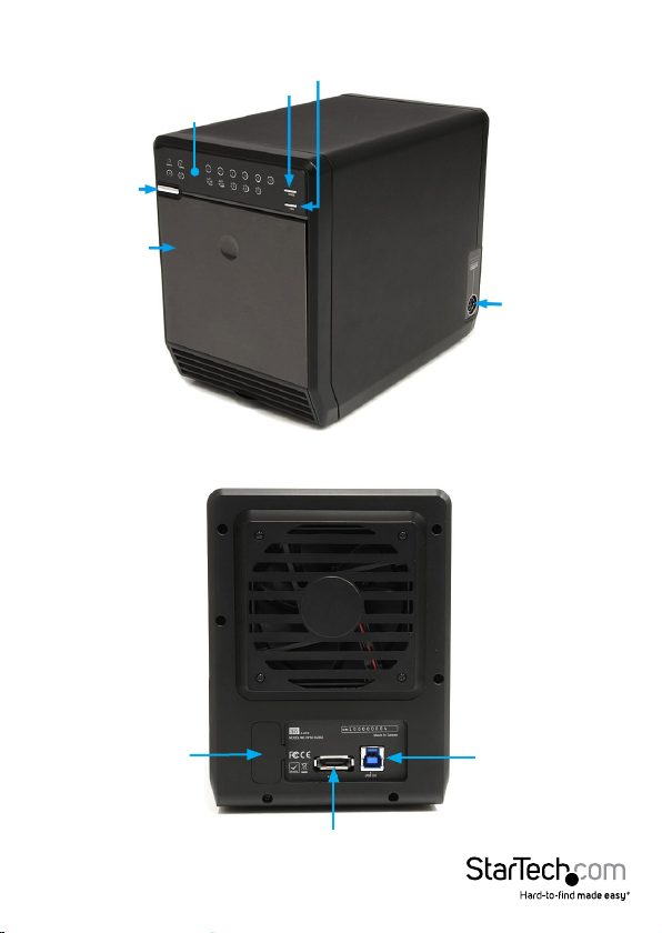
Front View
Power
button
Drive Bay
Front Cover
Rear View
LED indicators
Mode button
Fan button
DC Power
connector
RAID Mode
Conrmation
(under cover)
Instruction Manual
button
eSATA connector
2
USB 3.0 type B
connector
Page 6

Installation
WARNING! Hard drives and storage enclosures require careful handling, especially
when being transported. If you are not careful with your hard disk, lost data may
result. Always handle your hard drive and storage device with caution. Be sure that
you are properly grounded by wearing an anti-static strap when handling computer
components or discharge yourself of any static electricity build-up by touching a large
grounded metal surface (such as the computer case) for several seconds.
Hardware Installation
1. Attach the included Hard Drive Handles to each of the hard
drives with the supplied screws and screw driver.
*installation photos for reference only
2. Press the front door in to release the latch and open the door. The door is also
removable for easier access.
3. Inside will be a metal drive cage in front of the drive bays. Along the top of the drive
cage are two small tabs. Press them down to release the cage and remove it.
Instruction Manual
3
Page 7

4. Remove the cardboard inserts (if rst time setup) and then insert the hard drives
into the slots. Hard drives can be removed from the enclosure by pressing down on
the handles, then pulling them out.
5. Once all of the hard drives are installed, reinstall the metal cage and front door.
Make sure the bottom of the cage stays inside of the track before closing the cover.
6. Connect the power adapter DIN connector into the side of the enclosure and power
up the enclosure.
Driver Installation
No driver installation is required for the supported operating systems, as this enclosure
is natively supported, so the drivers are already installed.
Instruction Manual
4
Page 8

How to Use
RAID Mode
While the enclosure is powered on, press and hold the ‘Mode’ button for three (3)
seconds until one of the RAID LED’s start to ash. Pressing the ‘Mode’ button will now
switch between available RAID modes. Once set, press and hold the ‘Conrmation’
button on the back of the enclosure until the enclosure powers o. Connect the
enclosure to a computer system, then power the enclosure back on and it will now be
set for the desired RAID mode.
NOTE: Changing RAID modes will destroy any existing data on the hard drives
LED Status Description
ON
ON
OFF
ON
OFF
ON
OFF
ON
OFF
ON
SPAN: Spanning concatenates multiple hard drives into a
single large disk. Provides no performance or redundancy
benets.OFF
RAID 0 (Stripe): Striping combines multiple disk into a single
large disk array. The data is split evenly across each disk
simultaneously. Read/write performance is increased as a
result, but failure of any one disk will make the entire array
unusable.
RAID 1 (Mirror): Mirroring writes the same data across
multiple disk, creating a mirror copy. This provides
redundancy in case one drive fails.
RAID 3: Uses striping to write data to multiple disks like RAID
0, but reserves one disk for parity. The single parity disk is a
bottle-neck for writing since every write requires updating
the parity data. Failure of any one disk will still allow access to
the data, until the disk is replaced.
RAID 5: Uses striping to write data to multiple disks
simultaneously and distribute parity across multiple disks.
Failure of any one disk will still allow access to the data, until
the disk is replaced.
RAID 10 (1+0): Creates a stripped set, then mirrors each
stripped disk. Combines the performance of RAID 0 with the
redundancy of RAID 1.OFF
Instruction Manual
5
Page 9

Drive Status Indicators
LED Status Description
ON
OFF
ON
OFF
An error has been detected on one or more
hard drive.
RAID array is currently rebuilding.
eSATA/ USB Connectivity
The LED indicators will show which host interface is currently active on the enclosure.
To switch interfaces, shut the enclosure o and disconnect old cable and then connect
the new cable and turn the enclosure back on. Only one interface can be active at a
time, so it is recommended that only one cable be connected at a time to ensure the
proper interface is chosen.
LED Status Description
ON
OFF
ON
OFF
eSATA connection active
USB connection active
Instruction Manual
6
Page 10

Fan Speed Control
The cooling Smart Fan is automatically controlled by an integrated thermal sensor,
but can also be set manually. The fan is capable of running at 3 dierent speeds
depending on the temperature range of the enclosure (less than 45°C, between
45°C ~ 54°C, and greater than 55°C), or set manually to run constantly at a single speed.
LED Status Description
ON
OFF
ON
OFF
ON
OFF
ON
OFF
ON
OFF
Pressing the Fan button will toggle between Auto and Manual modes and then toggle
between the dierent manual fan speeds.
Smart Fan Auto Mode
Smart Fan Manual Mode
Low Speed - 1200 RPM
(Manual Mode only)
Medium Speed - 1800 RPM
(Manual Mode only)
High Speed - 2500 RPM
(Manual Mode only)
Instruction Manual
7
Page 11

Specications
Number of Drive Bays 4
Host Interface USB 3.0/ eSATA
Chipset ID JMicron JMB394 + JMB355 + JMS539
1 x USB 3.0 type B female
External Connectors
1 x DIN power connector
5 x Fan Speed/Mode
2 x Host Connection
LEDs
Fans 1 x 80mm
Compatible Hard Drives 3.5” SATA Hard Drives
Maximum Data Transfer Rate
RAID Modes Span, 0, 1, 3, 5, 10 (1+0)
Power Adapter 12V DC, 5000mA, 4-pin DIN plug
Enclosure Material Aluminum and Plastic
Operating Temperature 0°C ~ 40°C (32°F ~ 104°F)
Storage Temperature -20°C ~ 60°C (-4°F ~ 140°F)
Humidity 5% ~ 95% RH
Dimensions 215.0mm x 126.0mm x 170.0mm
Weight 1800g
Compatible Operating Systems
4 x HDD Power/Activity
1 x Hard Drive Error
Windows XP/ Server 2003/ Vista/
Server 2008 R2/ 7 (32/64-bit) / 8 (32/64-
bit) Mac OS X, Linux
1 x eSATA female
1 x Power
6 x RAID Mode
1 x Rebuild
USB 3.0: 5 Gbps
eSATA: 3 Gbps
Instruction Manual
8
Page 12

Technical Support
StarTech.com’s lifetime technical support is an integral part of our commitment to
provide industry-leading solutions. If you ever need help with your product, visit
www.startech.com/support and access our comprehensive selection of online tools,
documentation, and downloads.
For the latest drivers/software, please visit www.startech.com/downloads
Warranty Information
This product is backed by a two year warranty.
In addition, StarTech.com warrants its products against defects in materials
and workmanship for the periods noted, following the initial date of purchase.
During this period, the products may be returned for repair, or replacement with
equivalent products at our discretion. The warranty covers parts and labor costs only.
StarTech.com does not warrant its products from defects or damages arising from
misuse, abuse, alteration, or normal wear and tear.
Limitation of Liability
In no event shall the liability of StarTech.com Ltd. and StarTech.com USA LLP (or their
ocers, directors, employees or agents) for any damages (whether direct or indirect,
special, punitive, incidental, consequential, or otherwise), loss of prots, loss of business,
or any pecuniary loss, arising out of or related to the use of the product exceed the
actual price paid for the product. Some states do not allow the exclusion or limitation
of incidental or consequential damages. If such laws apply, the limitations or exclusions
contained in this statement may not apply to you.
Instruction Manual
9
Page 13

Hard-to-nd made easy. At StarTech.com, that isn’t a slogan. It’s a promise.
StarTech.com is your one-stop source for every connectivity part you need. From
the latest technology to legacy products — and all the parts that bridge the old and
new — we can help you nd the parts that connect your solutions.
We make it easy to locate the parts, and we quickly deliver them wherever they need
to go. Just talk to one of our tech advisors or visit our website. You’ll be connected to
the products you need in no time.
Visit www.startech.com for complete information on all StarTech.com products and
to access exclusive resources and time-saving tools.
StarTech.com is an ISO 9001 Registered manufacturer of connectivity and technology
parts. StarTech.com was founded in 1985 and has operations in the United States,
Canada, the United Kingdom and Taiwan servicing a worldwide market.
 Loading...